
QUINT4-PS/1AC/24DC/20/+/...
-
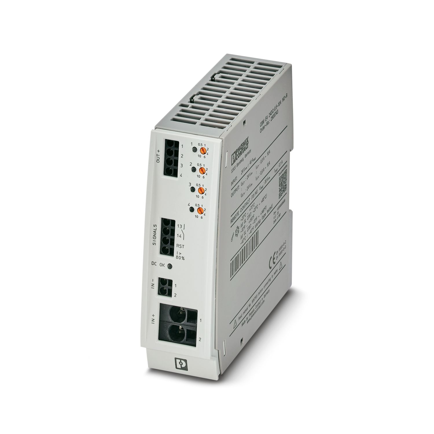
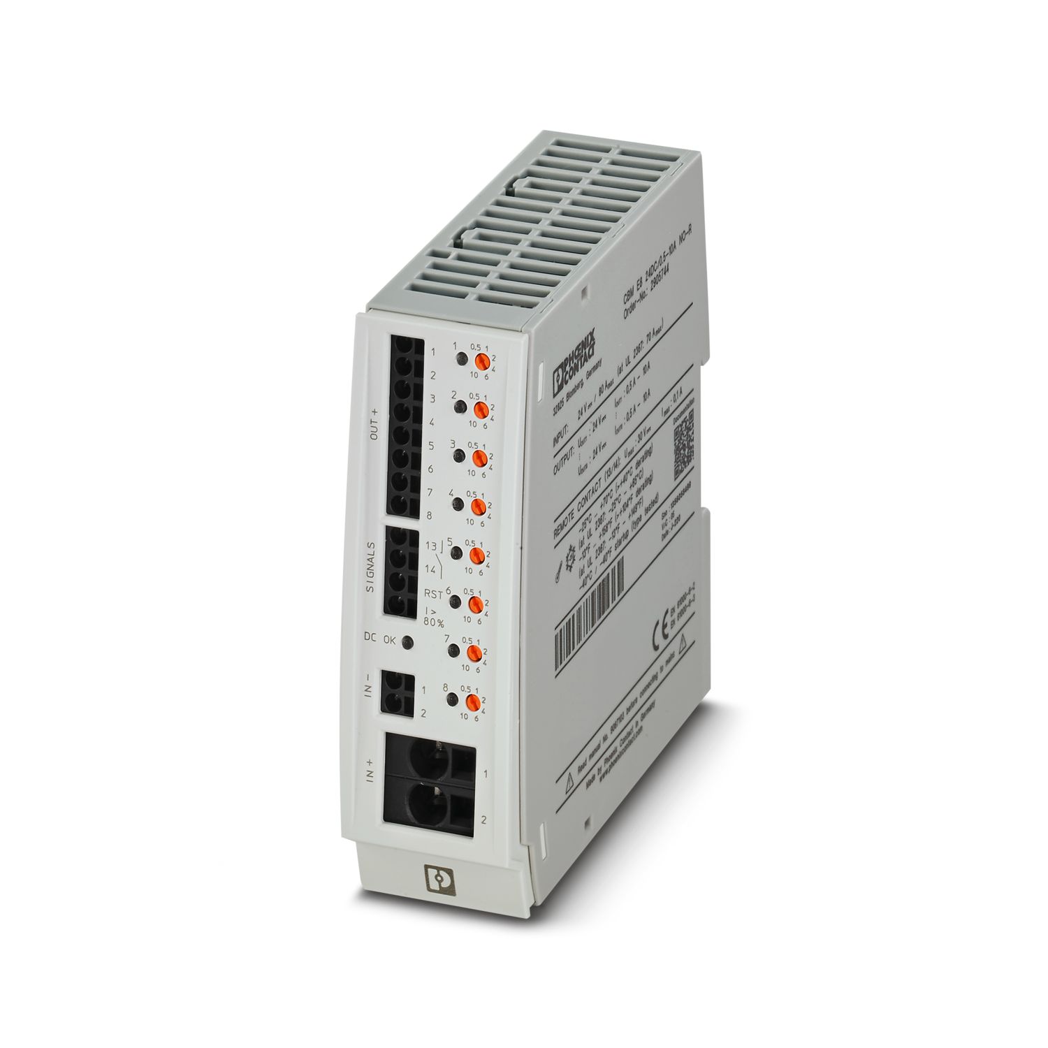
Power supply
2908940
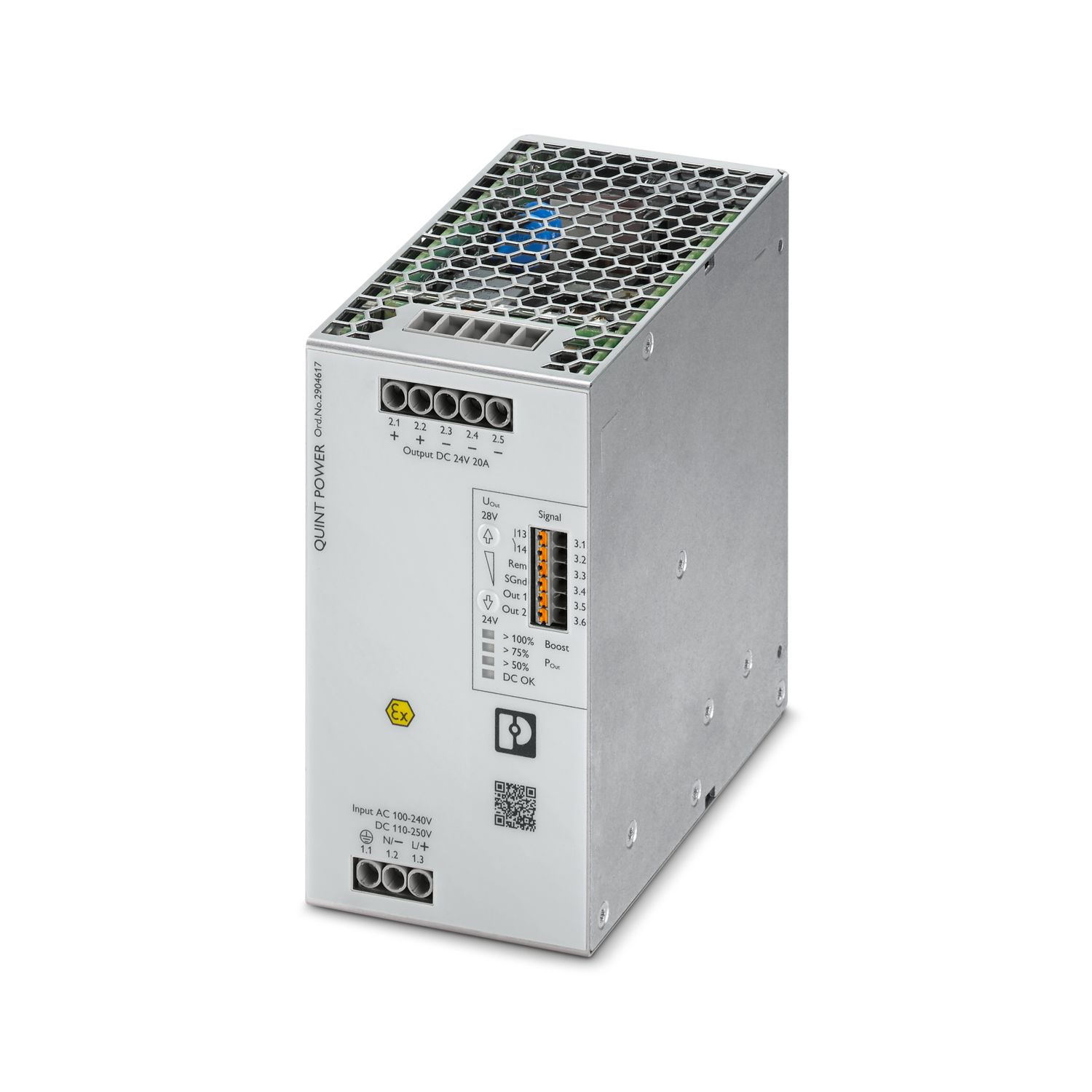
Version of the QUINT POWER primary-switched power supply for DIN rail mounting programmed according to customer specifications, with selectable output characteristic curve and SFB (Selective Fuse Breaking) Technology, protective coating and integrated decoupling MOSFET, input: 1-phase, output: 24 V DC/20 A
Free download available.
Downloads
Product details
| Control input (configurable) Rem | Output power ON/OFF (SLEEP MODE) |
| Default | Output power ON (>40 kΩ/24 V DC/open bridge between Rem and SGnd) |
| AC operation | |
| Network type | Star network |
| Nominal input voltage range | 100 V AC ... 240 V AC |
| Input voltage range | 100 V AC ... 240 V AC -15 % ... +10 % |
| Electric strength, max. | 300 V AC 60 s |
| Typical national grid voltage | 120 V AC |
| 230 V AC | |
| Voltage type of supply voltage | AC |
| Inrush current | typ. 10 A (at 25 °C) |
| Inrush current integral (I2t) | < 0.3 A2s |
| Inrush current limitation | 10 A (after 1 ms) |
| Frequency range (fN) | 50 Hz ... 60 Hz -10 % ... +10 % |
| 16.7 Hz (acc. to EN 50163) | |
| Mains buffering time | typ. 36 ms (120 V AC) |
| typ. 36 ms (230 V AC) | |
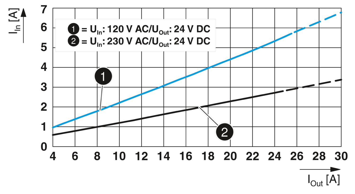
| Current consumption | 6.8 A (100 V AC) |
| 5.5 A (120 V AC) | |
| 2.8 A (230 V AC) | |
| 2.7 A (240 V AC) | |
| Nominal power consumption | 520 VA |
| Protective circuit | Transient surge protection; Varistor, gas-filled surge arrester |
| Switch-on time | < 1 s |
| Typical response time | 300 ms (from SLEEP MODE) |
| Input fuse | 12 A (slow-blow, internal) |
| Recommended breaker for input protection | 10 A ... 16 A (Characteristic B, C, D, K or comparable) |
| Discharge current to PE | < 3.5 mA |
| 1.7 mA (264 V AC, 60 Hz) | |
| DC operation | |
| Input voltage range | 110 V DC ... 250 V DC -18 % ... +40 % |
| Voltage type of supply voltage | DC |
| Current consumption | 6 A (110 V DC) |
| 2.5 A (250 V DC) | |
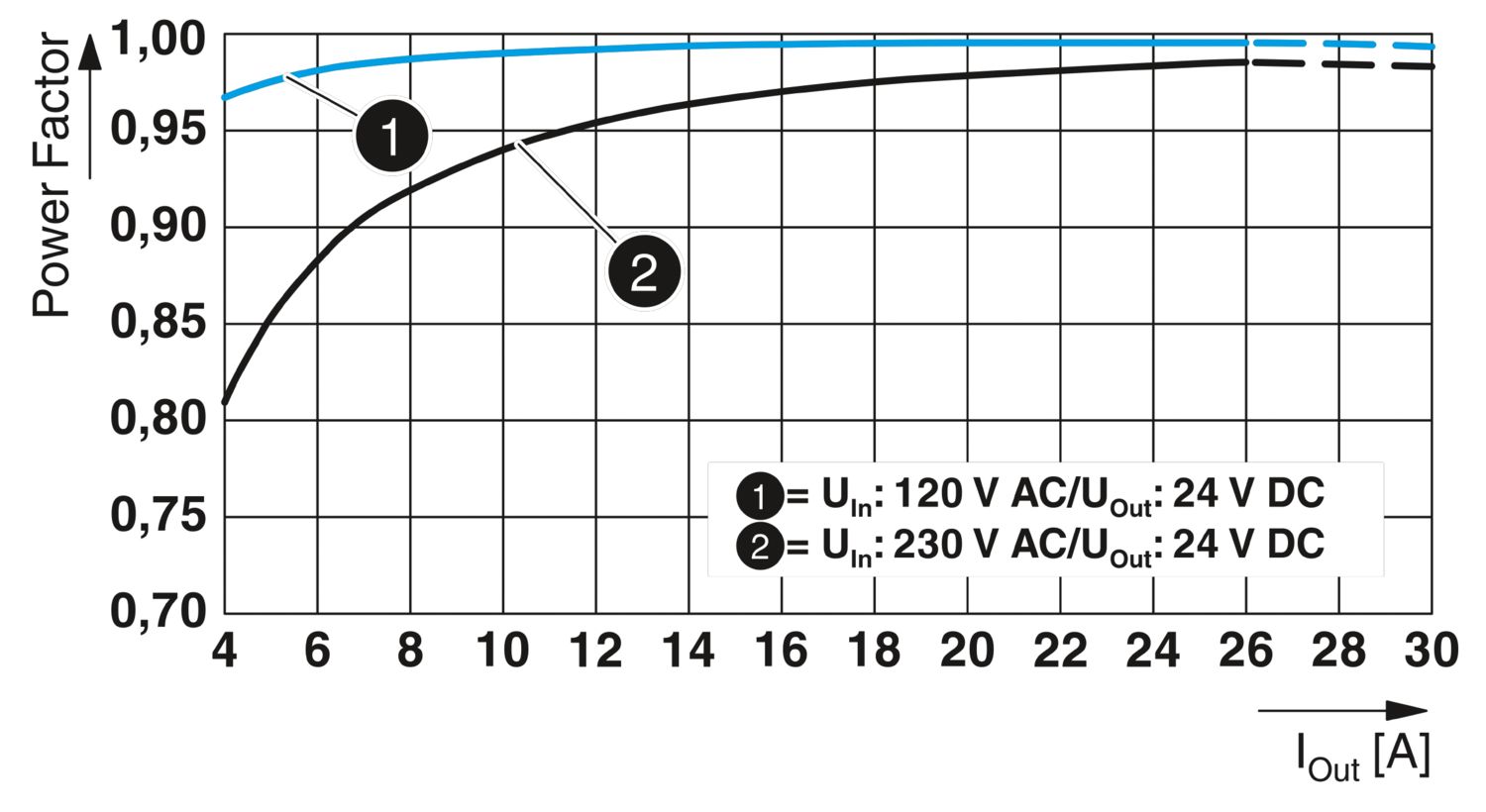
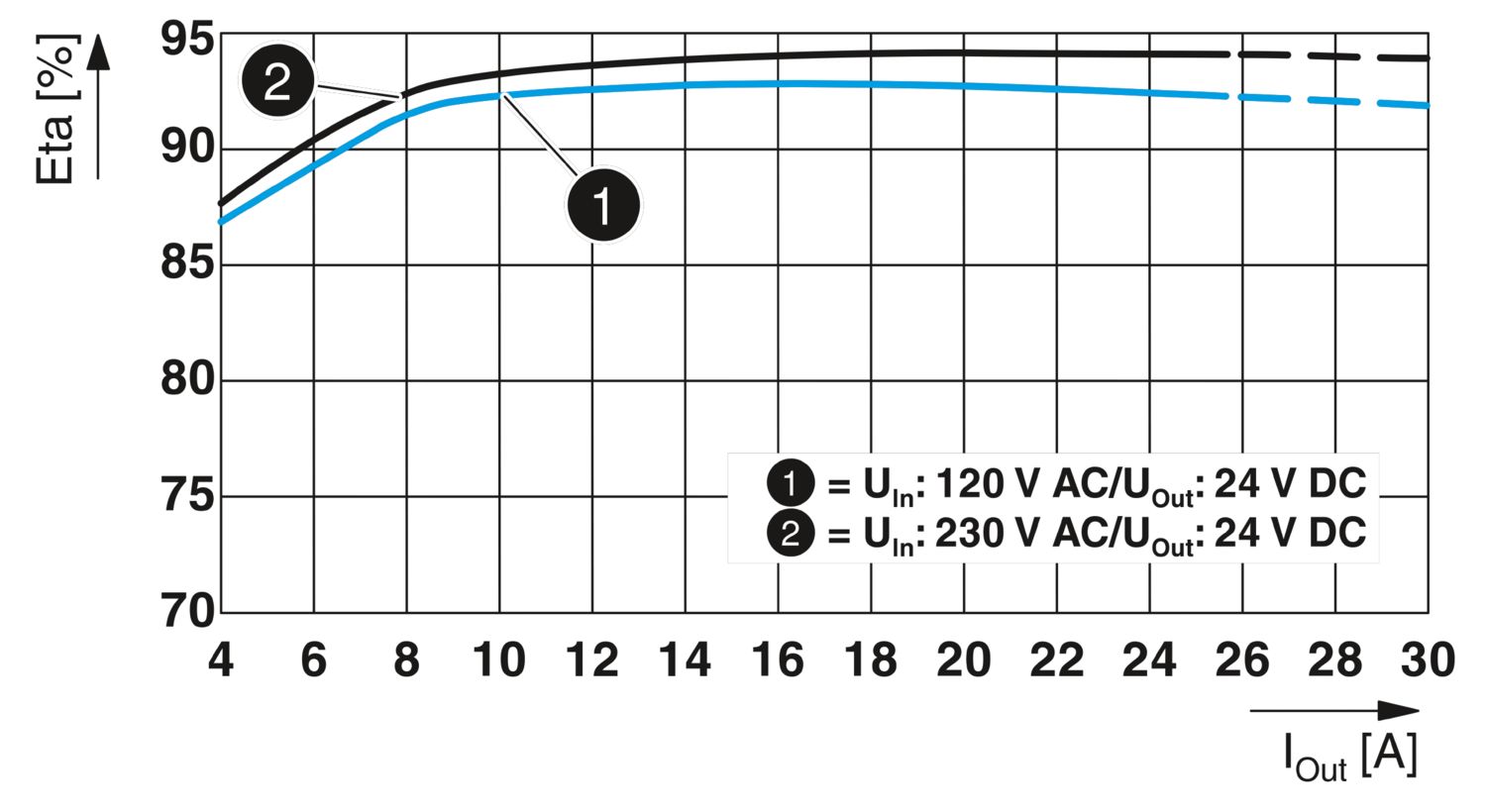
| Efficiency | typ. 92.7 % (120 V AC) |
| typ. 94.2 % (230 V AC) | |
| Nominal output voltage | 24 V DC |
| Setting range of the output voltage (USet) | 24 V DC ... 28 V DC (constant capacity) |
| Nominal output current (IN) | 20 A |
| Static Boost (IStat.Boost) | 25 A |
| Dynamic Boost (IDyn.Boost) | 30 A (5 s) |
| Selective Fuse Breaking (ISFB) | 120 A (15 ms) |
| Magnetic circuit breaker tripping | A1...A16 / B2...B13 / C1...C6 / Z1...Z16 |
| Feedback voltage resistance | ≤ 35 V DC |
| Protection against overvoltage at the output (OVP) | < 30 V DC (double protection with shut off within 20 ms) |
| Control deviation | < 0.5 % (Static load change 10 % ... 90 %) |
| < 2 % (Dynamic load change 10 % ... 90 %, (10 Hz)) | |
| < 0.25 % (change in input voltage ±10 %) | |
| Residual ripple | < 30 mVPP (with nominal values) |
| Short-circuit-proof | yes |
| No-load proof | yes |
| Output power | 480 W |
| 600 W | |
| 720 W | |
| Maximum no-load power dissipation | < 5 W (120 V AC) |
| < 5 W (230 V AC) | |
| Power loss nominal load max. | < 38 W (120 V AC) |
| < 30 W (230 V AC) | |
| Power dissipation SLEEP MODE | < 3 W (120 V AC) |
| < 3 W (230 V AC) | |
| Crest factor | typ. 1.54 (120 V AC) |
| typ. 1.6 (230 V AC) | |
| Rise time | < 1 s (UOut = 10 % ... 90 %) |
| Connection in parallel | yes, for redundancy and increased capacity |
| Connection in series | yes |
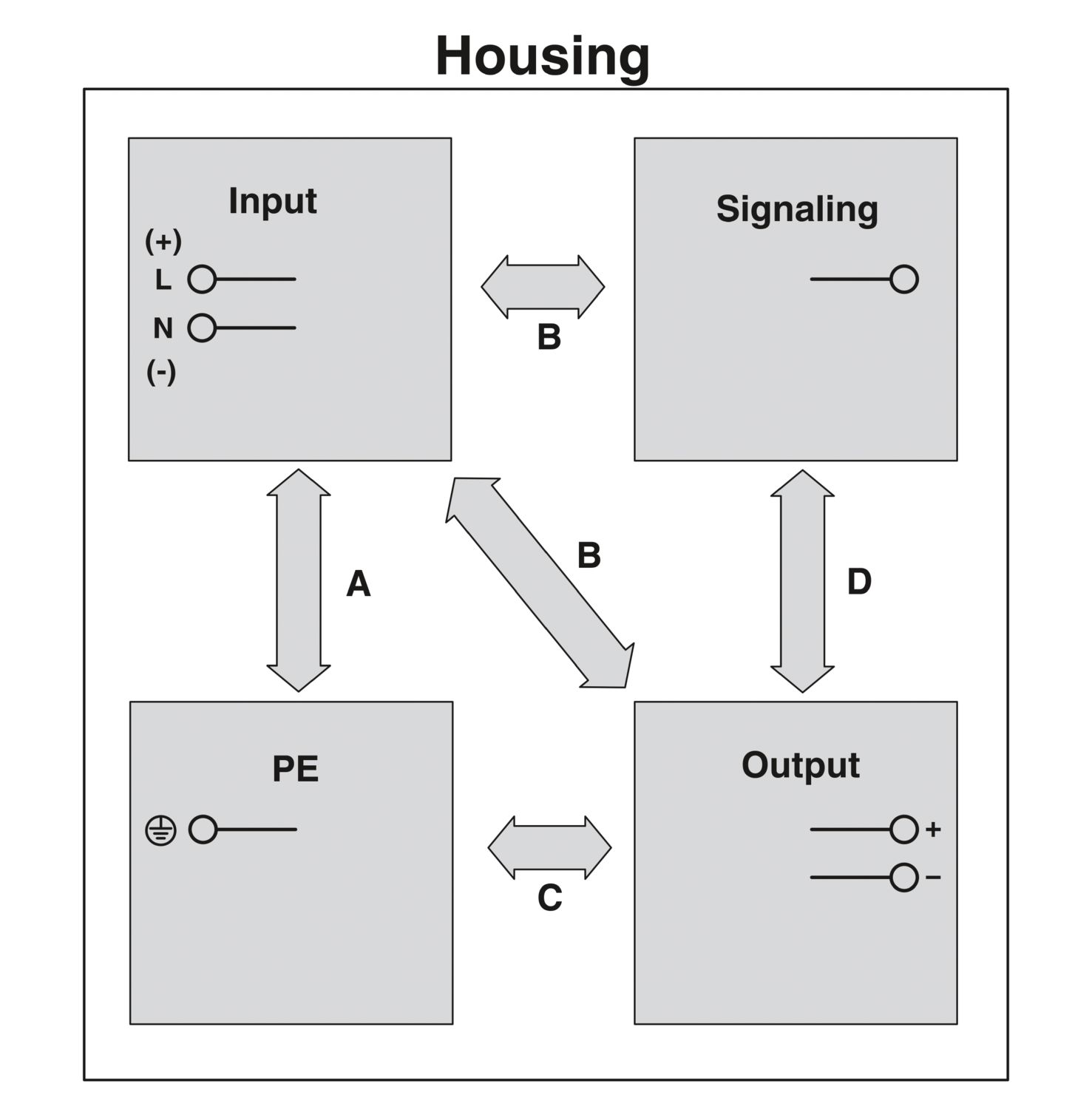
| Signal | |
| Signal ground SGnd | Reference potential for Out1, Out2, and Rem |
| Signal Out 1 (configurable) | |
| Digital | 24 V DC 20 mA |
| Default | 24 V DC 20 mA 24 V DC for UOut > 0.9 x USet |
| Signal Out 2 (configurable) | |
| Digital | 24 V DC 20 mA |
| Analog | 4 mA ... 20 mA ±5 % (Load ≤400 Ω) |
| Default | 24 V DC 20 mA 24 V DC for POut < PN |
| Signal relay 13/14 (configurable) | |
| Default | closed (Uout > 0.9 USet) |
| Digital | 24 V DC 1 A |
| 30 V AC/DC 0.5 A | |
| Input | |
| Connection method | Screw connection |
| Conductor cross section, rigid min. | 0.2 mm² |
| Conductor cross section, rigid max. | 6 mm² |
| Conductor cross section flexible min. | 0.2 mm² |
| Conductor cross section flexible max. | 4 mm² |
| Single conductor/flexible terminal point with ferrule with plastic sleeve, min. | 0.25 mm² |
| Single conductor/flexible terminal point with ferrule with plastic sleeve, max. | 4 mm² |
| Single conductor/flexible terminal point with ferrule without plastic sleeve, min. | 0.25 mm² |
| Single conductor/flexible terminal point with ferrule without plastic sleeve, max. | 4 mm² |
| Conductor cross section AWG min. | 30 |
| Conductor cross section AWG max. | 10 |
| Stripping length | 8 mm |
| Tightening torque, min | 0.5 Nm |
| Tightening torque max | 0.6 Nm |
| Output | |
| Connection method | Screw connection |
| Conductor cross section, rigid min. | 0.2 mm² |
| Conductor cross section, rigid max. | 6 mm² |
| Conductor cross section flexible min. | 0.2 mm² |
| Conductor cross section flexible max. | 4 mm² |
| Single conductor/flexible terminal point with ferrule with plastic sleeve, min. | 0.25 mm² |
| Single conductor/flexible terminal point with ferrule with plastic sleeve, max. | 4 mm² |
| Single conductor/flexible terminal point with ferrule without plastic sleeve, min. | 0.25 mm² |
| Single conductor/flexible terminal point with ferrule without plastic sleeve, max. | 4 mm² |
| Conductor cross section AWG min. | 30 |
| Conductor cross section AWG max. | 10 |
| Stripping length | 8 mm |
| Tightening torque, min | 0.5 Nm |
| Tightening torque max | 0.6 Nm |
| Signal | |
| Connection method | Push-in connection |
| Conductor cross section, rigid min. | 0.2 mm² |
| Conductor cross section, rigid max. | 1 mm² |
| Conductor cross section flexible min. | 0.2 mm² |
| Conductor cross section flexible max. | 1.5 mm² |
| Single conductor/flexible terminal point with ferrule with plastic sleeve, min. | 0.2 mm² |
| Single conductor/flexible terminal point with ferrule with plastic sleeve, max. | 0.75 mm² |
| Single conductor/flexible terminal point with ferrule without plastic sleeve, min. | 0.2 mm² |
| Single conductor/flexible terminal point with ferrule without plastic sleeve, max. | 1.5 mm² |
| Conductor cross section AWG min. | 24 |
| Conductor cross section AWG max. | 16 |
| Stripping length | 8 mm |
| Types of signaling | LED |
| Floating signal contact | |
| Active signal output Out1 (digital, configurable) | |
| Active signal output Out2 (analog, configurable) | |
| Remote contact | |
| Signal ground SGnd | |
| Signal output | |
| POut | > 100 % (LED lights up yellow, output power > 480 W) |
| > 75 % (LED lights up green, output power > 360 W) | |
| > 50 % (LED lights up green, output power > 240 W) | |
| UOut | > 0.9 x USet (LED lights up green) |
| < 0.9 x USet (LED flashes green) | |
| Number of phases | 1 |
| Insulation voltage input/output | 4 kV AC (type test) |
| 2 kV AC (routine test) | |
| Switching frequency | 90.00 kHz ... 110.00 kHz (Auxiliary converter stage) |
| 80.00 kHz ... 280.00 kHz (Main converter stage) | |
| 50.00 kHz ... 70.00 kHz (PFC stage) |
| Product type | Power supply |
| Product family | QUINT POWER |
| MTBF (IEC 61709, SN 29500) | > 868000 h (25 °C) |
| > 524000 h (40 °C) | |
| > 239000 h (60 °C) | |
| Insulation characteristics | |
| Protection class | I |
| Degree of pollution | 2 |
| Life expectancy (electrolytic capacitors) | |
| Current | 10 A |
| Temperature | 40 °C |
| Time | 392000 h |
| Additional text | 120 V AC |
| Life expectancy (electrolytic capacitors) | |
| Current | 10 A |
| Temperature | 40 °C |
| Time | 447000 h |
| Additional text | 230 V AC |
| Life expectancy (electrolytic capacitors) | |
| Current | 20 A |
| Temperature | 25 °C |
| Time | 378000 h |
| Additional text | 120 V AC |
| Life expectancy (electrolytic capacitors) | |
| Current | 20 A |
| Temperature | 25 °C |
| Time | 499000 h |
| Additional text | 230 V AC |
| Life expectancy (electrolytic capacitors) | |
| Current | 20 A |
| Temperature | 40 °C |
| Time | 133000 h |
| Additional text | 120 V AC |
| Life expectancy (electrolytic capacitors) | |
| Current | 20 A |
| Temperature | 40 °C |
| Time | 176000 h |
| Additional text | 230 V AC |
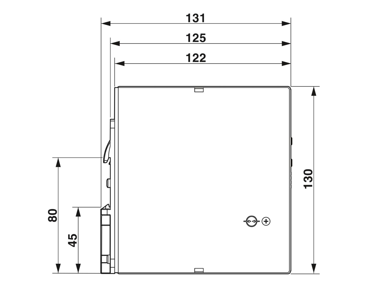
| Dimensional drawing |
|
| Width | 70 mm |
| Height | 130 mm |
| Depth | 125 mm |
| Installation dimensions | |
| Installation distance right/left | 5 mm / 5 mm |
| Installation distance top/bottom | 50 mm / 50 mm |
| Alternative assembly | |
| Width | 122 mm |
| Height | 130 mm |
| Depth | 73 mm |
| Mounting type | DIN rail mounting |
| Assembly note | Alignable: horizontally 0 mm at Pout <50% PN, 5 mm at Pout ≥50% PN, next to active components 15 mm, vertically 50 mm |
| Mounting position | horizontal DIN rail NS 35, EN 60715 |
| With protective coating | yes |
| Flammability rating according to UL 94 (housing / terminal blocks) | V0 |
| Housing material | Metal |
| Hood version | Stainless steel X6Cr17 |
| Side element version | Aluminum |
| Ambient conditions | |
| Degree of protection | IP20 |
| Ambient temperature (operation) | -40 °C ... 75 °C (> 60 °C Derating: 2,5 %/K) |
| Ambient temperature (storage/transport) | -40 °C ... 85 °C |
| Maximum altitude | ≤ 5000 m (> 2000 m, observe derating) |
| Climatic class | 3K3 (in acc. with EN 60721) |
| Max. permissible relative humidity (operation) | ≤ 100 % (at 25 °C, non-condensing) |
| Shock | 18 ms, 30g, in each space direction (according to IEC 60068-2-27) |
| Vibration (operation) | 5 Hz ... 100 Hz resonance search 2.3g, 90 min., resonance frequency 2.3g, 90 min. (according to DNV GL Class C) |
| Rail applications | EN 50121-3-2 |
| EN 50121-4 | |
| EN 50121-5 | |
| EN 50163 | |
| IEC 62236-3-2 | |
| IEC 62236-4 | |
| IEC 62236-5 | |
| HART FSK Physical Layer Test Specification Compliance | Output voltage UOut compliant |
| Standard – Limitation of mains harmonic currents | EN 61000-3-2 |
| Standard - Electrical safety | IEC 60950-1/VDE 0805 (SELV) |
| Explosive atmosphere | IEC 60079-0 |
| IEC 60079-7 | |
| IEC 60079-11 | |
| IEC 60079-15 | |
| Standard – Safety extra-low voltage | IEC 60950-1 (SELV) |
| EN 60204-1 (PELV) | |
| Standard - safety for equipment for measurement, control, and laboratory use | IEC 61010-1 |
| Standard - Safety of transformers | EN 61558-2-16 |
| Approval - requirement of the semiconductor industry with regard to mains voltage dips | SEMI F47-0706, EN 61000-4-11 |
| Overvoltage category | |
| EN 60950-1 | II (≤ 5000 m) |
| EN 61010-1 | II (≤ 5000 m) |
| EN 62477-1 | III (≤ 2000 m) |
| CSA | CAN/CSA-C22.2 No. 60950-1-07 |
| CSA-C22.2 No. 107.1-01 | |
| Shipbuilding approval | DNV GL applied for |
| SIQ | BG (type approved) |
| UL approvals | UL Listed UL 508 |
| UL/C-UL Recognized UL 60950-1 | |
| UL ANSI/ISA-12.12.01 Class I, Division 2, Groups A, B, C, D (Hazardous Location) | |
| Conformity/Approvals | |
| ATEX | II 3 G Ex ec ic nC IIC T4 Gc X |
| IECEx | IECEx SIQ 18.0005X |
| Ex ec ic nC IIC T4 Gc | |
| Functional Safety in accordance with IEC 61508 | SIL 3 |
| Electromagnetic compatibility | Conformance with EMC Directive 2014/30/EU |
| Low Voltage Directive | Conformance with Low Voltage Directive 2014/35/EC |
| Interference emission | Interference emission in accordance with EN 61000-6-3 (residential and commercial) and EN 61000-6-4 (industrial) |
| EMC requirements for noise immunity | EN 61000-6-1 |
| EN 61000-6-2 | |
| EMC requirements, power plant | IEC 61850-3 |
| EN 61000-6-5 | |
| Conducted noise emission | |
| Standards/regulations | EN 55016 |
| EN 61000-6-3 (Class B) | |
| Noise emission | |
| Standards/regulations | Additional basic standard EN 61000-6-5 (immunity in switching devices), IEC/EN 61850-3 (power supply) |
| Noise emission | |
| Standards/regulations | EN 55016 |
| EN 61000-6-3 (Class B) | |
| DNV GL conducted noise emissions | |
| DNV | Class A |
| Additional text | Area power distribution |
| DNV GL noise radiation | |
| DNV | Class B |
| Additional text | Bridge and deck area |
| Harmonic currents | |
| Standards/regulations | EN 61000-3-2 |
| Frequency range | 0 kHz ... 2 kHz |
| Flicker | |
| Standards/regulations | EN 61000-3-3 |
| Frequency range | 0 kHz ... 2 kHz |
| Electrostatic discharge | |
| Standards/regulations | EN 61000-4-2 |
| Electrostatic discharge | |
| Contact discharge | 8 kV (Test Level 4) |
| Discharge in air | 15 kV (Test Level 4) |
| Comments | Criterion A |
| Electromagnetic HF field | |
| Standards/regulations | EN 61000-4-3 |
| Electromagnetic HF field | |
| Frequency range | 80 MHz ... 1 GHz |
| Test field strength | 20 V/m (Test Level 3) |
| Frequency range | 1 GHz ... 6 GHz |
| Test field strength | 10 V/m (Test Level 3) |
| Comments | Criterion A |
| Fast transients (burst) | |
| Standards/regulations | EN 61000-4-4 |
| Fast transients (burst) | |
| Input | 4 kV (Test Level 4 - asymmetrical) |
| Output | 4 kV (Test Level 4 - asymmetrical) |
| Signal | 4 kV (Test Level 4 - asymmetrical) |
| Comments | Criterion A |
| Surge voltage load (surge) | |
| Input | 3 kV (Test Level 4 - symmetrical) |
| 6 kV (Test Level 4 - asymmetrical) | |
| Output | 1 kV (Test Level 3 - symmetrical) |
| 2 kV (Test Level 3 - asymmetrical) | |
| Signal | 4 kV (Test Level 4 - asymmetrical) |
| Comments | Criterion A |
| Conducted interference | |
| Standards/regulations | EN 61000-4-6 |
| Conducted interference | |
| Input/output/signal | asymmetrical |
| Frequency range | 0.15 MHz ... 80 MHz |
| Comments | Criterion A |
| Voltage | 10 V (Test Level 3) |
| Power frequency magnetic field | |
| Standards/regulations | EN 61000-4-8 |
| Frequency | 16.7 Hz |
| 50 Hz | |
| 60 Hz | |
| Test field strength | 100 A/m |
| Additional text | 60 s |
| Comments | Criterion A |
| Frequency | 50 Hz |
| 60 Hz | |
| Frequency range | 50 Hz ... 60 Hz |
| Test field strength | 1 kA/m |
| Additional text | 3 s |
| Frequency | 0 Hz |
| Test field strength | 300 A/m |
| Additional text | DC, 60 s |
| Voltage dips | |
| Standards/regulations | EN 61000-4-11 |
| Voltage | 230 V AC |
| Frequency | 50 Hz |
| Voltage dip | 70 % |
| Number of periods | 0.5 / 1 / 25 / 30 periods |
| Additional text | Test Level 2 |
| Comments | Criterion A: 0.5 / 1 / 25 / 30 periods |
| Voltage dip | 40 % |
| Number of periods | 5 / 10 / 50 periods |
| Additional text | Test Level 2 |
| Comments | Criterion A |
| Voltage dip | 0 % |
| Number of periods | 0,5 / 1 / 5 / 50 / 250 periods |
| Additional text | Test Level 2 |
| Comments | Criterion A: 0.5 / 1 period Criterion B: 5 / 50 / 250 periods |
| Pulse-shape magnetic field | |
| Standards/regulations | EN 61000-4-9 |
| Test field strength | 1000 A/m |
| Comments | Criterion A |
| Attenuated sinusoidal oscillations (ring wave) | |
| Standards/regulations | EN 61000-4-12 |
| Input | 2 kV (Test Level 4 - symmetrical) |
| 4 kV (Test Level 4 - asymmetrical) | |
| Comments | Criterion A |
| Asymmetrical conducted disturbance variables | |
| Standards/regulations | EN 61000-4-16 |
| Test level 1 | 15 Hz 150 Hz (Test Level 4) |
| Voltage | 30 V 3 V |
| Test level 2 | 150 Hz 1.5 kHz (Test Level 4) |
| Voltage | 3 V |
| Test level 3 | 1.5 kHz 15 kHz (Test Level 4) |
| Voltage | 3 V 30 V |
| Test level 4 | 15 kHz 150 kHz (Test Level 4) |
| Voltage | 30 V |
| Test level 5 | 16.7 Hz 50 Hz 60 Hz (Test Level 4) |
| Voltage | 30 V (Permanent) |
| Test level 6 | 150 Hz 180 Hz (Test Level 4) |
| Voltage | 30 V (Permanent) |
| Test level 7 | 16.7 Hz 50 Hz 60 Hz (Test Level 4) |
| Voltage | 300 V (1 s) |
| Comments | Criterion A |
| Attenuated oscillating wave | |
| Standards/regulations | EN 61000-4-18 |
| Input, output (test level 1) | 100 kHz 1 MHz (Test Level 3 - symmetrical) |
| Voltage | 1 kV |
| Input, output (test level 2) | 10 MHz |
| Voltage | 1 kV |
| Input, output (test level 3) | 100 kHz 1 MHz (Test Level 3 - asymmetrical) |
| Voltage | 2.5 kV |
| Signals (test level 1) | 100 kHz 1 MHz (Test Level 3 - symmetrical) |
| Voltage | 1 kV |
| Signals (test level 2) | 100 kHz 1 MHz (Test Level 3 - asymmetrical) |
| Voltage | 2.5 kV |
| Comments | Criterion A |
| Attenuated oscillating magnetic field | |
| Standards/regulations | EN 61000-4-10 |
| Test field strength | 110 A/m |
| Test level 1 | 100 kHz |
| Test field strength | 110 A/m |
| Test level 2 | 1 MHz |
| Comments | Criterion A |
| Criteria | |
| Criterion A | Normal operating behavior within the specified limits. |
| Criterion B | Temporary impairment to operational behavior that is corrected by the device itself. |
| Criterion C | Temporary adverse effects on the operating behavior, which the device corrects automatically or which can be restored by actuating the operating elements. |

Your advantages
SFB technology trips standard circuit breakers selectively, loads that are connected in parallel continue working
Easy system extension thanks to static boost; starting of difficult loads thanks to dynamic boost
Preventive function monitoring indicates critical operating states before errors occur
High degree of immunity, thanks to integrated gas-filled surge arrester and mains failure bridging time of more than 20 milliseconds
Integrated decoupling MOSFET for 1+1 and n+1 redundancy
Protective coating and ATEX/IECEx approval
Safe supply with SIL 3 certification in accordance with IEC 61508
Robust design, thanks to metal housing and wide temperature range from -40°C to +75°C
Worldwide use thanks to the wide range input and international approval package