
HC-M-HS 200/40-MOD-ST
-
Contact insert module
1637168
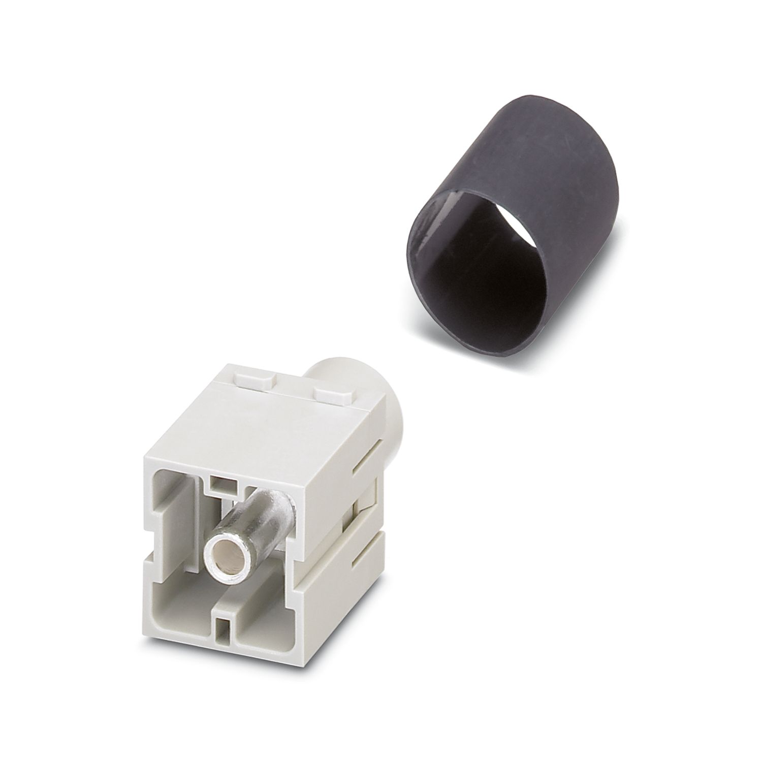
HEAVYCON contact insert module, connector, 1-pos., for axial screw connection, 200 A, 25 mm2 ... 40 mm2
Product details
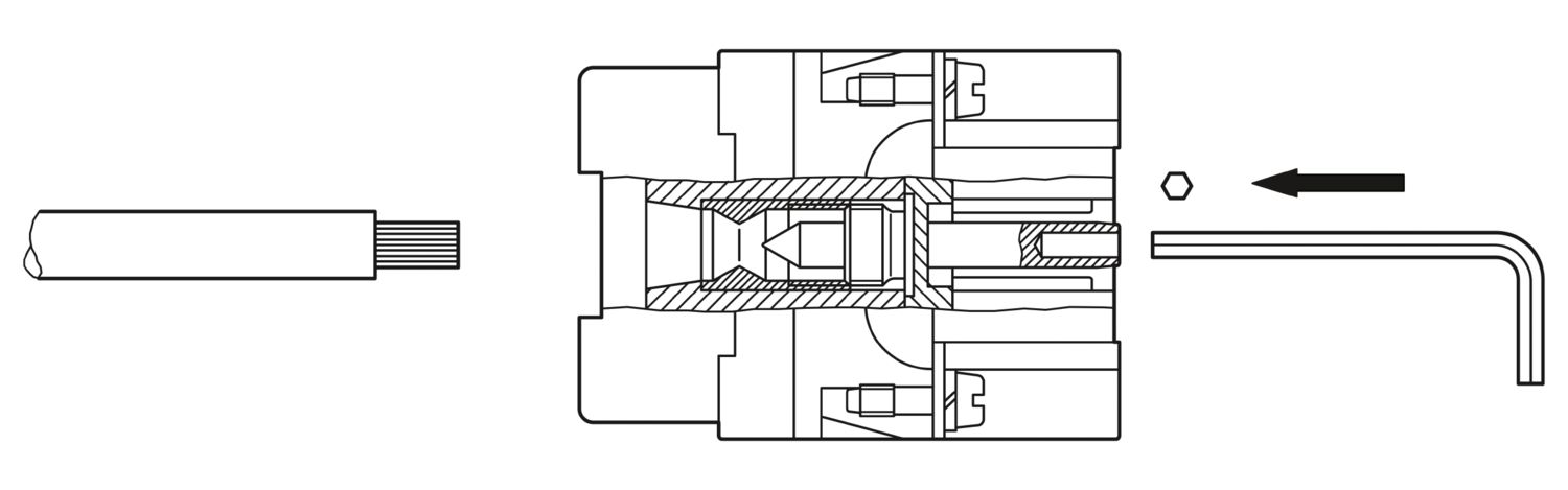
| Assembly note | - Use only flexible conductors, - Connection of wires with 5 mm an Allen wrench, - Housing height h ≥ 72 mm, - Connectors may only be operated without load/voltage. |
| Note regarding axial connection technology: Only for stranded wires. The specified conductor cross-sections refer to the geometric cross section of the cable used. Use of cables with a geometric cross section very different from the cable's nominal cross section should be checked before use. The wiring space of the axial screw method is designed for fine strand cables according to VDE 0295 Class 5. Deviating cable structures (e.g., Class 6 cables) should be checked before use. Connection Before starting to connect, ensure that the tapered screw is turned back all the way (chamber is open). The cables must not be twisted. The wires should be inserted as far as they will go in the contact chamber (until the insulation touches the contact). Hold wires in position and use socket wrench to tighten. The used wire end should be cut off before connecting again. The connection screw may only be retightened once to prevent the litz wires from breaking. To prevent damage to the contact, the wire/cable should be mechanically intercepted at an appropriate distance from the connection point (e.g., by using a plate cutout). DIN VDE 0100-520:2003-06 contains information on how to do this correctly. The module cannot be used simultaneously with the HC-B..-TMB-SD-IP65 and HC-B..-TMS-SD-IP65 protective covers. |
|
| Hexagonal socket | SW 5 |
| Product type | Modular contact insert |
| Series | HC-M-HS |
| Application | Power |
| Number of positions | 1 |
| Connection profile | 1 |
| Number of module slots | 2 |
| Insulation characteristics | |
| Overvoltage category | III |
| Degree of pollution | 3 |
| Connection technology | |
| Connection technology | Axial screw connection |
| Conductor connection | |
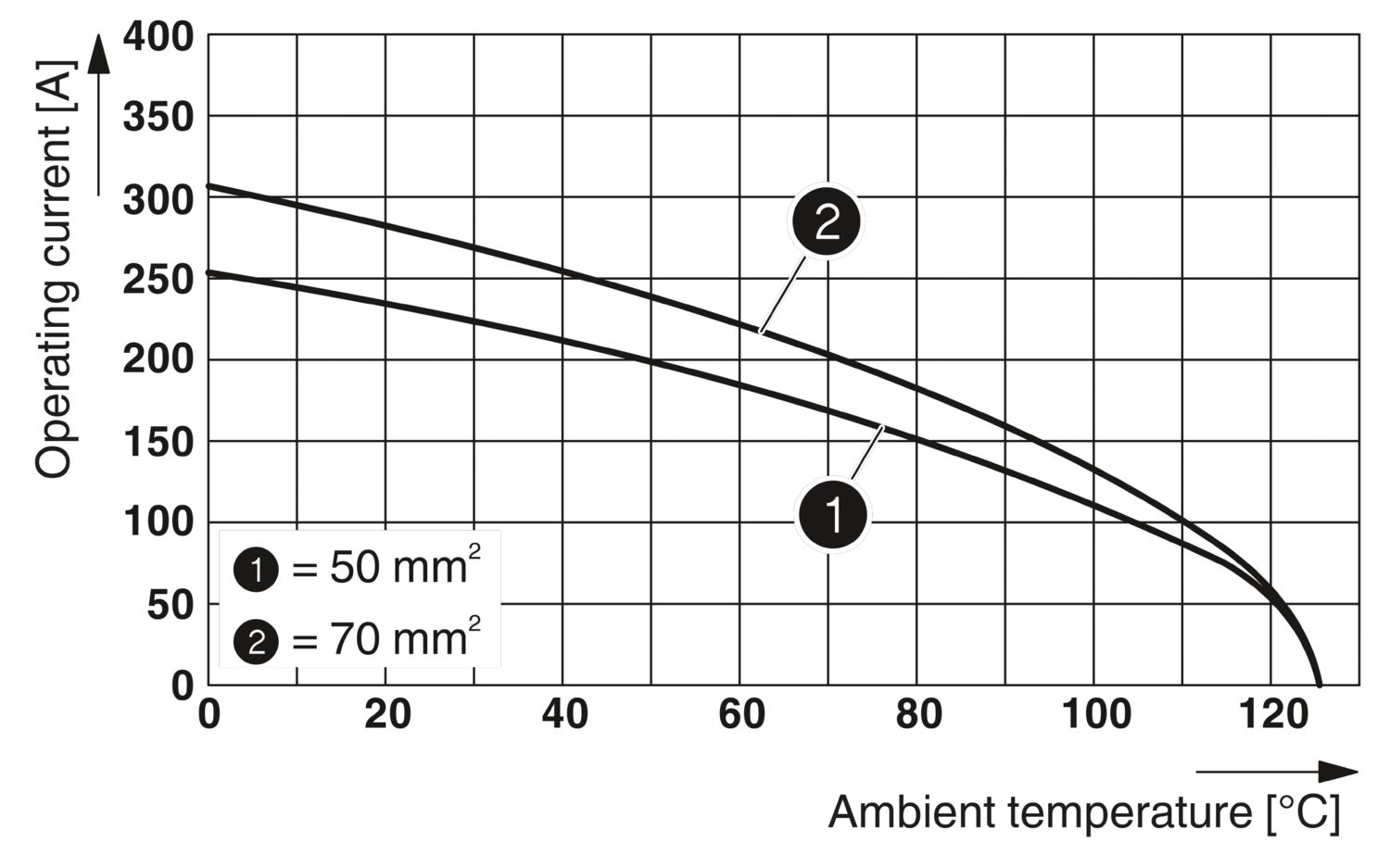
| Conductor cross-section | 25 mm² ... 40 mm² (The cross section specification refers to the geometric cross section of the cable used) |
| Connection cross section AWG | 3 ... 2 |
| Tightening torque | 8 Nm (25 mm² ... 35 mm²) |
| 9 Nm (40 mm²) | |
| Stripping length of the individual wire | 16 mm |
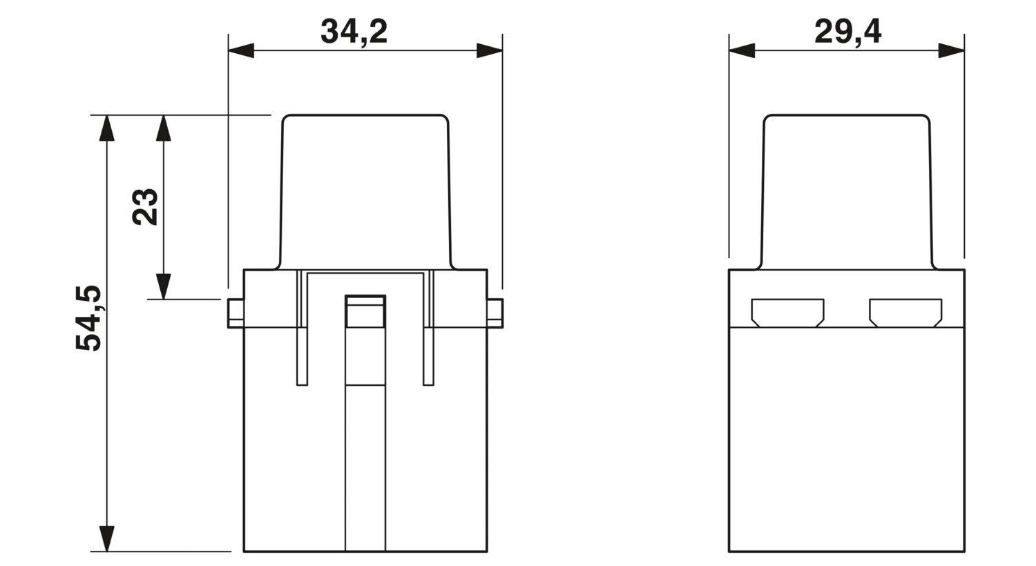
| Dimensional drawing |
|
| Width | 34.2 mm |
| Height | 54.5 mm |
| Length | 29.4 mm |
| Mechanical characteristics | |
| Minimum housing height | 72 mm |
| Rated voltage (III/3) | 1000 V |
| Rated surge voltage | 8 kV |
| Rated current | 200 A |
| Mechanical data | |
| Insertion/withdrawal cycles | ≥ 500 |
| Flammability rating according to UL 94 | V0 |
| Contact material | Copper alloy |
| Contact surface material | Ag |
| Contact carrier material | PC |
| Ambient conditions | |
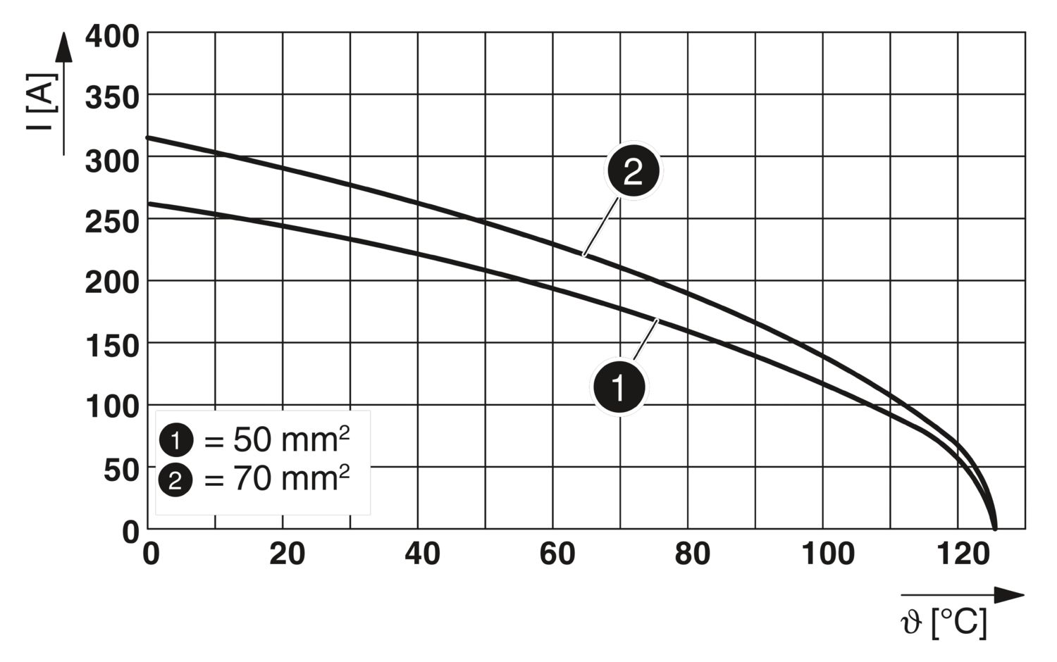
| Ambient temperature (operation) | -40 °C ... 125 °C |