The configurable and individually scalable PSRmodular safety system is a flexible safety solution for monitoring your machine or system. The safe extension module provides the system with additional safe analog inputs.
PSR-M-EF7-XC-SAI4-PI
-
Extension module
1337851
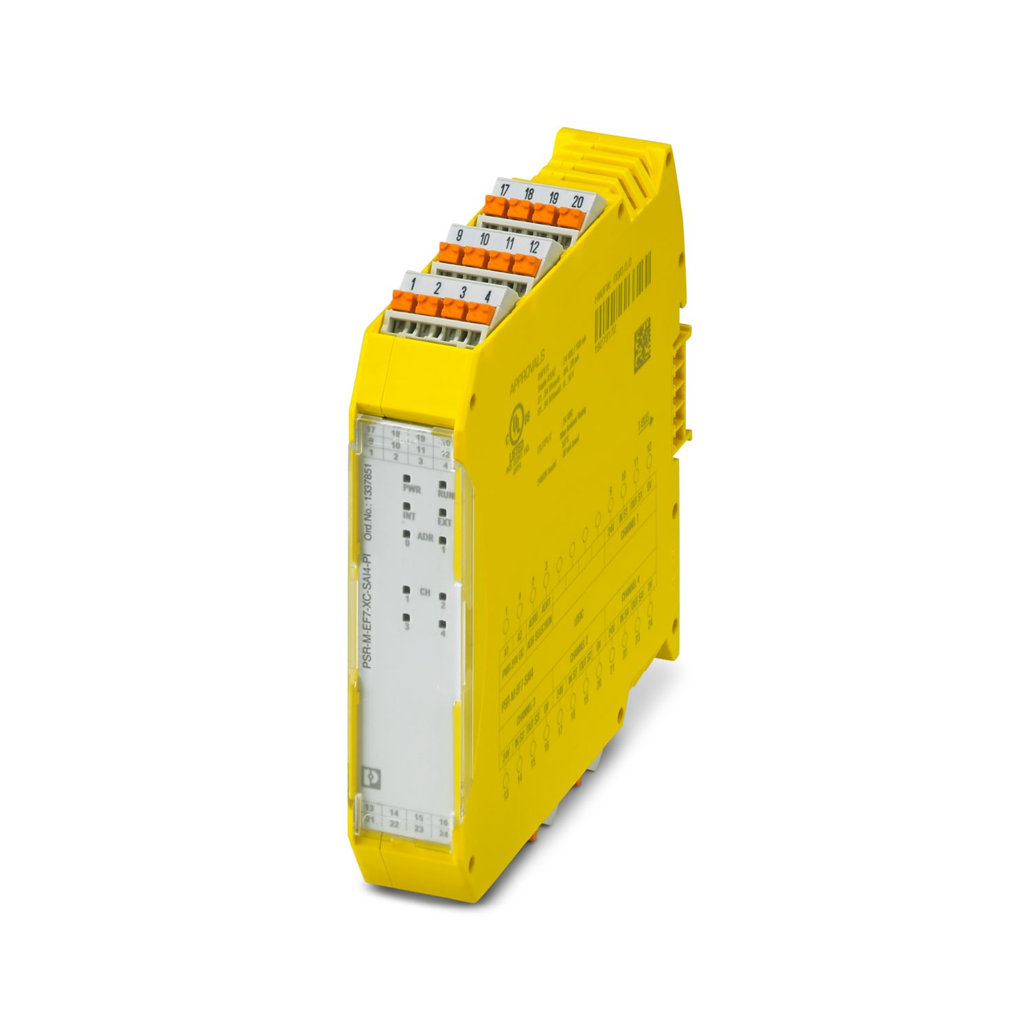
Safe extension module with 4 safe analog inputs, 0 V ... 10 V; 0 mA or 4 mA ... 20 mA; TBUS interface, up to Cat. 4/PL e, SIL 3, plug-in Push-in terminal block, TBUS connector included
Free download available.
Downloads
Product details
| Product type | Safety device |
| Application | Analog IN |
| Control | 1 and 2 channel |
| Insulation characteristics | |
| Protection class | III |
| Insulation characteristics | |
| Overvoltage category | II |
| Degree of pollution | 2 |
| Times | |
| Response time | see user manual |
| Restart time | min. 5 s (Boot time) |
| max. 10 s (Boot time) | |
| Maximum power dissipation for nominal condition | 2.76 W (with max. permissible load) |
| Nominal operating mode | 100% operating factor |
| Interfaces | DIN rail TBUS for connection to the master module, supplied as standard |
| Rated surge voltage/insulation | Basic insulation 4 kV between all current paths and housing |
| Electrical isolation, 0.5 kV functional insulation between logic and analog inputs and between the analog inputs | |
| Supply | |
| Designation | A1/A2 |
| Rated control circuit supply voltage US | 19.2 V DC ... 28.8 V DC |
| Rated control circuit supply voltage US | 24 V DC -20 % / +20 % (external fuse, typically 6 A) |
| Rated control supply current IS | typ. 82 mA (without sensor supply) |
| typ. 212 mA (with sensor supply) | |
| Power consumption at US | typ. 1.96 W (without sensor supply) |
| typ. 5.08 W (with sensor supply) | |
| Inrush current | max. 14 A (Δt = 1 ms at Us) |
| Filter time | typ. 5 ms (in the event of voltage dips at Us) |
| Protective circuit | Serial protection against polarity reversal |
| Analog | |
| Input name | IN S1, IN S2, IN S3, IN S4 |
| Description of the input | Safety-oriented analog inputs, configurable as current or voltage inputs, galvanically isolated |
| Number of inputs | 4 |
| Connection technology | 2-conductor, 3-conductor or 4-conductor (2-conductor sensor signal + 2-conductor sensor supply) |
| Note regarding the connection technology | shielded |
| Scanning rate | 2.5/5/10/16.6/20/50/60/100/200/400/800/1000/2000/4000 Hz |
| Current input signal | 0 mA ... 25 mA (Measuring range) |
| 0 mA ... 20 mA (Configurable measuring range with diagnostics range 20.1 mA ... 23 mA) | |
| 4 mA ... 20 mA (Configurable measuring range with diagnostics range 20.1 mA ... 23 mA (upper limit), 2.5 mA ... 3.8 mA (lower limit)) | |
| Voltage input signal | 0 V ... 12 V (Measuring range) |
| 0 V ... 10 V (Configurable measuring range with diagnostics range 10.05 V ... 11.5 V (upper limit), 0.1 V (lower limit)) | |
| Max. permissible current | max. 35 mA (as current input) |
| Permissible voltage | max. 24 V (as current input) |
| max. 14 V (as voltage input) | |
| Input resistance current input | 290 Ω ±25 % (incl. internal protective circuit) |
| Input resistance of voltage input | 185 kΩ ±25 % |
| A/D converter resolution | 16 bit |
| Resolution (current) | 381 nA |
| Resolution (voltage) | 152 µV |
| Precision | typ. ± 2 % (as current input, relative to the measuring range final value) |
| max. ± 2.5 % (as current input) | |
| typ. ± 1 % (as voltage input, relative to the measuring range final value) | |
| max. ± 1.5 % (as voltage input) | |
| Temperature coefficients | typ. ± 0.07 %/K |
| max. ± 0.07 %/K | |
| Limit frequency (3 dB) | 160 Hz (RC low pass, 1st order, as current input) |
| 4 Hz (RC low pass, as voltage input) | |
| Frequency | 20 Hz (max. recommended sensor signal frequency, as current input) |
| 2 Hz (max. recommended sensor signal frequency, as voltage input) | |
| Permissible cable length | max. 100 m (per input) |
| Protective circuit | Overload protection of the current inputs |
| Overload protection of the voltage inputs | |
| Sensor supply: OUT S1/0V ...OUT S4/0V | |
| Description | Sensor supply voltage per analog input |
| Supply voltage | 24 V DC ±3 % |
| Current | max. 30 mA (Sensor current recording per channel) |
| Short-circuit-proof | yes |
| Protective circuit | Overload protection Overload detection at 38 mA |
| Connection technology | |
| pluggable | yes |
| Conductor connection | |
| Connection method | Push-in connection |
| Conductor cross-section rigid | 0.2 mm² ... 2.5 mm² |
| Conductor cross-section flexible | 0.2 mm² ... 2.5 mm² |
| Conductor cross-section AWG | 24 ... 14 |
| Stripping length | 10 mm |
| Status display | 4 x LED (yellow, red) |
| Operating voltage display | 1 x LED (green) |
| Width | 22.61 mm |
| Height | 107.74 mm |
| Depth | 113.6 mm |
| Color (Housing) | yellow (RAL 1018) |
| Housing material | Polyamide PA non-reinforced |
| Safety data | |
| Stop category | 0 |
| Safety data: EN ISO 13849 | |
| Performance level (PL) | e (2-channel wiring) |
| d (1-channel wiring) | |
| Safety data: IEC 61508 - High-demand for 2-channel wiring | |
| Safety Integrity Level (SIL) | 3 |
| Safety data: IEC 61508 - High-demand for 1-channel wiring | |
| Safety Integrity Level (SIL) | 2 |
| Safety data | |
| Safety Integrity Level (SIL) | 2 |
| Safety data: EN IEC 62061 | |
| Safety Integrity Level (SIL) | 3 (2-channel wiring) |
| 2 (1-channel wiring) | |
| Ambient conditions | |
| Degree of protection | IP20 |
| Min. degree of protection of inst. location | IP54 |
| Ambient temperature (operation) | -10 °C ... 70 °C (observe derating) |
| Ambient temperature (operation) (ATEX) | -10 °C ... 50 °C (When used in potentially explosive areas. Observe derating) |
| Ambient temperature (storage/transport) | -20 °C ... 85 °C |
| Maximum altitude | ≤ 2000 m (Above sea level) |
| Max. permissible humidity (storage/transport) | 95 % (non-condensing) |
| Max. permissible relative humidity (operation) | 95 % (non-condensing) |
| Shock | 10g for Δt = 16 ms (continuous shock, 1000 shocks in each space direction) |
| Vibration (operation) | 10 Hz ... 150 Hz, 2g |
| ATEX | |
| Note | T4: for -10°C Tamb +50°C |
| UL Ex, USA / Canada | |
| Identification | Class I, Div. 2, Groups A, B, C, D T4 |
| Note | T4: for -10°C Tamb +50°C |
| CE | |
| Identification | CE-compliant |
| Environmental simulation test | |
| Identification | G3 |
| Certificate | ISA-S71.04 |
| Mounting type | DIN rail mounting |
| Assembly note | Observe derating |
| Mounting position | vertical or horizontal |
| Item number | 1337851 |
| Packing unit | 1 pc |
| Minimum order quantity | 1 pc |
| Sales key | DNA362 |
| Product key | DNA362 |
| GTIN | 4063151639730 |
| Weight per piece (including packing) | 192.5 g |
| Weight per piece (excluding packing) | 159 g |
| Country of origin | IT |
ECLASS
| ECLASS-13.0 | 27371819 |
| ECLASS-15.0 | 27371819 |
| ECLASS-15.0 ASSET | 27250101 |
ETIM
| ETIM 9.0 | EC001449 |
UNSPSC
| UNSPSC 21.0 | 39122200 |
| EU RoHS | |
| Fulfills EU RoHS substance requirements | Yes (No exemptions) |
| China RoHS | |
| Environment friendly use period (EFUP) |
EFUP-E
No hazardous substances above the limits
|
| EU REACH SVHC | |
| REACH candidate substance (CAS No.) | No substance above 0.1 wt% |
Compatible products
Your advantages
Cost-effective safety solution with a high level of adaptability to individual requirements
Fast startup, thanks to easy hardware and software configuration
Machine downtimes minimized with comprehensive, easy-to-understand diagnostics
Tool-free and time-saving installation thanks to Push-in technology
Low housing width of just 22.6 mm
Up to Cat. 4/PL e in accordance with ISO 13849-1, SIL 3 in accordance with EN IEC 62061, SIL 3 in accordance with IEC 61508
Suitable for elevator applications in accordance with EN 81-20
Corrosion protection through protective coating on the PCB
Suitable for ATEX Zone 2 or Class I Zone 2
PHOENIX CONTACT Ltd
Unit 15C, 906-930 Great South Road, Penrose, Auckland 1061, New Zealand