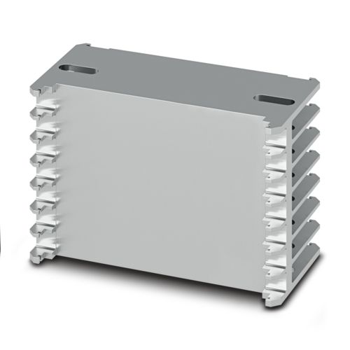
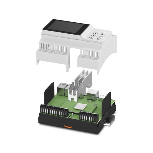
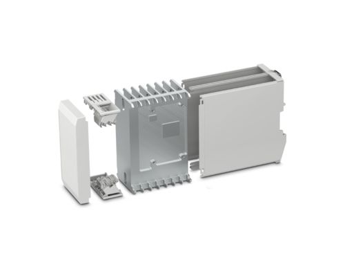
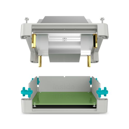
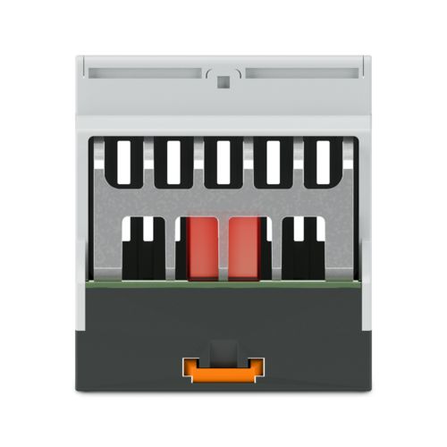
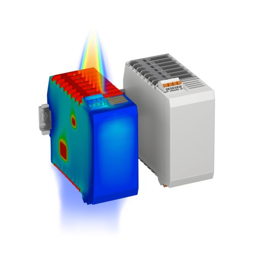
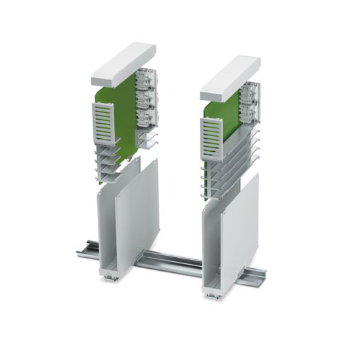
Our Annual Stock Take will take place from Thursday the 23rd November to Friday 24th November. If you have an order due to ship on either the Thursday or the Friday – These orders should, where stock is available, ship on Wednesday the 22nd November or Monday 27th November.
Please note: our annual stock take will take place during 28-29th November. No orders will be shipped during this time. Thank you for your understanding.
Our annual stock-take will take place on 24-25th November. No Orders will be shipped on these days, please plan your orders accordingly. We apologise for any inconvenience this may cause.
Thermal management for electronics housings has become an important discipline in the thermal design of devices. The miniaturization of electromechanics and electronics is leading to ever higher power densities and thus to the electronics heating up.
Passive heatsinks for electronics housings allow the finished devices to be used even in thermally demanding applications. By performing extensive thermal simulations, Phoenix Contact also supports you in optimizing your PCB layout.
Your advantages
Simple preestimation of the maximum power that can be dissipated using clear derating diagrams
Online thermal simulation supports rapid analysis of thermal conditions
Heatsinks tailored to the customer layout ensure reliable heat dissipation
Extensive thermal simulations help achieve the optimum arrangement of components on the printed circuit board
Simplified development process: all the services needed for your specific device design
Services in all development phases
To carry out an initial check of the maximum power that can be dissipated from your housing application, we offer you derating diagrams tailored to the housing. You can localize the subsequent operating point and read off the maximum power dissipation accordingly. This preliminary stage of the thermal design is suitable for estimating the required housing size and makes an initial statement about the need for an integrable heatsink.
Use our intuitive online simulation tool to analyze the heat generation of your application in the early phase of development.
First, use the configurator for ICS housings to configure your housing to suit your application. Next, position hot spots on your PCB and define the thermal boundary conditions of your application. You will receive your application-specific results directly by e-mail.
Based on our online simulation, we will provide you with a very precise thermal analysis of your application with our simulation service. Various component configurations on your printed circuit board are first simulated and evaluated. If you choose to integrate heatsinks into your device at a later date, the application will be perfectly thermally tuned via simulations to ensure that it can be used perfectly under the given boundary conditions.
Thermal management in device development is becoming an increasingly important discipline. We will be happy to advise you on the initial design of your printed circuit board, give you a recommendation on thermal interface materials (TIMs), and tailor the heatsink to your components.
Thermal simulations and tailored heatsinks for thermally demanding applications
High-performance components and demanding ambient conditions lead to high power densities in electrical devices. With our products and services, we can help you with the correct thermal design of your end application.
ICS series modular electronics housings for IoT applications
The solutions offered by the ICS modular electronics housings are as varied as the requirements for future-oriented devices in industrial automation.
Passive heatsinks for ICS series electronics housings enable the finished devices to be used even in thermally demanding applications. By performing extensive thermal simulations, Phoenix Contact also supports you in optimizing your PCB layout.
The thermal requirements for device applications are increasingly stringent. The UCS heatsink solutions enable targeted passive heat dissipation from UCS housings. In combination with individually adapted heat spreaders, they support the optimum thermal design of your devices.
Heat is optimally dissipated from the housing via heatsink solutions that are perfectly tailored to the housing. The heatsinks can be tailored individually to the printed circuit board layout.
Heatsinks tailored to the housings
The passive aluminum heatsinks are perfectly tailored to the geometric conditions of the housing system. They provide optimum cooling in the smallest possible space.
The thermal path
Suitable thermal interface materials (TIMs), optional heat spreaders, and heatsinks can optimize the heat paths.
Optimum guidance in the housing
Our heatsinks make the housing even more stable. The integrated guides not only thermally optimize your subsequent application, but also make it very robust.
Customized milling of the heatsink
Every printed circuit board layout is different. Therefore, our heatsinks can be milled to the desired component height as standard.
Heat spreader insert
Optional heat spreaders can bridge larger distances between the component to be cooled and the heatsink.
Sliding heatsink base
In the heatsink series for the ICS housing, the heatsinks are designed as continuous cast profiles. The heatsink base can be moved depending on the component height.
Simulation design
Online and detailed simulations allow components, heatsinks, and housings for your application to be designed with perfect thermal properties.
High degree of design freedom
The heatsinks can also be shaped as fillers. The cooling element does not run continuously along the printed circuit board. This leaves enough space for other components.
FAQs on the subject of thermal management during device development
Phoenix Contact will support you with catalog values, online simulations, personal consultations including simulation services, and individually adapted heatsinks.
The component that heats strongly (the hotspot) is connected to the heatsink by thermal interface material (TIM). In the case of the UCS housing system, optionally inserted heat spreaders can also bridge larger distances between the component to be cooled and the heatsink.
The optimum thermal connection is implemented by individual adjustments of the heatsink. This is usually done by a milling operation on the heatsink.
Small and powerful components, high data rates, dust, and insufficient ventilation of the housing are reasons for a high temperature difference compared to the environment.
The graphs of the diagrams provide information on which power the components may supply in the respective housing in order not to exceed a temperature difference to the environment. The slope of the straight line describes the thermal conductance of the system. The cases shown differ, on the one hand, in that one features full-surface heating while the other features heating of a hotspot of 20 mm x 20 mm and, on the other hand, in that one has a printed circuit board installed in the housing and one does not have a housing.
The integrated heatsinks from Phoenix Contact dissipate heat from the hotspot by means of heat conduction via thermal interface materials (TIM). The heatsink releases this heat in the form of radiant energy and via convection between the slats to the environment. The stack effect is utilized, during which the heated air rises and is displaced by cold air.
E-paper
Overview of the electronics housings portfolio
Discover housings for the DIN rail and outdoor use and learn how flexibly you can adapt electronics housings to your individual needs.