Tank fill-level monitoring, temperature monitoring, flow rate measurements, pumping stations and well chains, pipeline monitoring, leakage monitoring, chemical park infrastructure, energy management, in Ex zone 2 areas

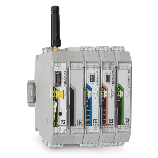
Radioline is the wireless system for large systems. Special features include extremely easy assignment of inputs and outputs by simply turning the thumbwheel – no programming is necessary.
With Trusted Wireless 2.0 technology, Radioline is the ideal choice for reliable use in industrial environments.
Use the thumbwheel to assign the I/O modules within a network to one another. Simply set the I/O modules that need to communicate with one another to the same number.
For example, set a digital input to IO MAP address 12 and then also set the assigned digital output to IO MAP address 12 – the signals will then be distributed correctly throughout the entire system.


Tank fill-level monitoring, temperature monitoring, flow rate measurements, pumping stations and well chains, pipeline monitoring, leakage monitoring, chemical park infrastructure, energy management, in Ex zone 2 areas

Water treatment plants, remote pumping station connection, remote well connection, rotating parts (such as a scraper bridge), fill-level monitoring

Energy technology: Wind farms, surface mining, power station infrastructure, transformer stations, hydroelectric power stations
Conveying technology: Monitoring motors on conveyor belts, error messages, status messages on mobile vehicles

Control of light signal systems, car park displays, variable traffic sign systems, and signage boards (for example).

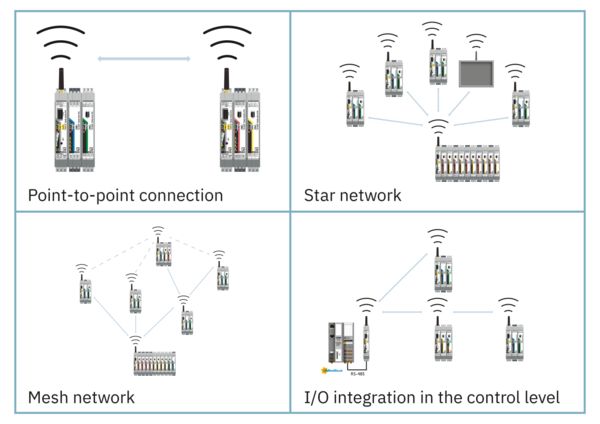
Radioline in point-to-point connection, star networks, and mesh networks.

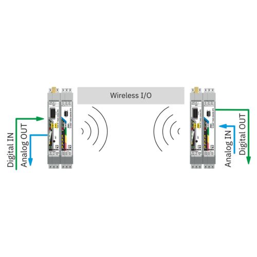
Transmission of I/O signals (wire in/wire out)
Radioline enables easy I/O signal distribution throughout the network and the creation of various network structures (delivery state). I/O mapping significantly simplifies signal distribution in large systems.
Assign inputs and outputs quickly by simply turning the thumbwheel. In this way you can distribute and multiply I/O signals freely in your network using I/O extension modules – without the need for any programming.

Serial data transmission
Radioline can be used to network multiple controllers or serial I/O devices quickly and easily using wireless technology.
In this way, serial RS-232/RS-485 cables can be replaced.

Data transmission from I/O stations to a controller
With Radioline, I/O modules can be connected to the controller directly via the integrated RS-232 and RS-485 interface by means of wireless communication using the Modbus protocol.
You can connect I/O extension modules to each remote station in the network. The I/O signals are stored in an integrated Modbus register in the base station wireless module where they can be accessed by the controller at any time.
In addition to signals, diagnostic parameters, such as the wireless signal quality of the individual devices, are also provided in the Modbus register to ensure continuous monitoring of the wireless system.

Data transmission of I/O signals and Modbus data
This mode combines “Serial data mode” and “PLC/Modbus RTU mode”. In this mode, each station in the network acts as an independent Modbus server. You can connect I/O extension modules to each station in the network. The process data is stored locally in the Modbus memory map for the respective station. At the same time, additional Modbus servers can be connected to each station via RS-232 or RS-485, and addressed via the respective Modbus address.
All diagnostic data of the wireless network can be read from the wireless base station via Modbus.

 |
 |
 |
 |
|
|---|---|---|---|---|
| RAD-868-IFS wireless module | RAD-900-IFS-... wireless module | RAD-2400-IFS-... wireless module | RAD-RS485-IFS bus coupler | |
| Region | Europe | North/South America (RAD-900-IFS), Australia/New Zealand (RAD-900-IFS-AU) | Worldwide (RAD-2400-IFS), Japan (RAD-2400-IFS-JP) | Worldwide |
| Frequency band | 868 MHz | 900 MHz | 2.4 GHz | - |
| Typical range with line of sight | <20 km (suitable for large distances with obstacles) | <32 km (suitable for large distances with obstacles) | <5 km | <1.2 km (using existing 2-wire copper cables or more with converter or repeater) |
| Topology | Point-to-point, star, mesh | Point-to-point, star, mesh | Point-to-point, star, mesh | Point-to-point, line |
| Number of network devices | <99 | <250 | <250 | <99 |
| Typical transmission time (point-to-point, bidirectional – depending on frequency band, data rate, telegram length, network structure/size) | >2 s (I/O mode), >390 ms (serial mode) | >200 ms (I/O mode), >25 ms (serial mode) | >200 ms (I/O mode), >25 ms (serial mode) | >80 ms (I/O mode) |
 |
 |
|
|---|---|---|
| Outdoor switchgear and controlgear assembly RAD-RUGGED-BOX-CONF | Outdoor box RAD-900-DAIO6 | |
| Region | Worldwide | North America and Canada |
| Frequency band | 868 MHz / 900 MHz / 2.4 GHz (configurable) | 900 MHz |
| Input/output signals | RS-485, type and number of input and output signals can be configured | 2x digital input/output, 1x analog input/output |
| Power supply | 100 V AC...240 V AC | 10.8 V DC...30.5 V DC or 100 V AC...240 V AC |
| Ambient temperature | -25°C ... +55°C | -40°C...+70°C (DC), -40°C...+65°C (AC) |
| Type of protection | IP66 | NEMA 4X |
| Dimensions | 300 mm x 240 mm x 150 mm | 220 mm x 120 mm x 90 mm |
 |
 |
|
|---|---|---|
| 4-channel digital I/O modules | 8-channel digital I/O modules | |
| Input signal (DI, NAMUR, AI, Pt 100) | 4 x 0…250 V AC/DC | 8 x 0...30.5 V DC or 2x pulse (<100 Hz, 32 bit (PLC/Modbus RTU or dual mode)), 4 x NAMUR |
| Output signal (DOR, DO, AO) | 4 x 250 V AC/DC, 5 A (relay output) | 8 x 30.5 V DC, 200 mA (transistor output) |
| Modules that can be combined in I/O mode | RAD-DI4-IFS (IN), RAD-NAM4-IFS (IN), RAD-DOR4-IFS (OUT) | RAD-DI8-IFS (IN), RAD-DO8-IFS (OUT) |
 |
 |
 |
|
|---|---|---|---|
| Digital/analog I/O module | Analog I/O modules | Temperature I/O module | |
| Input signal (DI, NAMUR, AI, Pt 100) | 2 x 0 … 250 V AC/DC, 1 x 0/4…20 mA | 4 x 0/4 ... 20 mA, 4 x 0 ... 5/10 V | 4 x Pt 100 (-50°C ... +250°C), 2-/3-conductor connection |
| Output signal (DOR, DO, AO) | 2 x 0 … 250 V AC/DC, 1 x 0/4…20 mA | 4 x 0/4…20 mA, 0…10 V DC | - |
| Modules that can be combined in I/O mode | RAD-DAIO6-IFS (IN/OUT) | RAD-AI4-IFS (IN), RAD-AI4-U-IFS (IN), RAD-AO4-IFS (OUT) | RAD-PT100-4-IFS (IN), RAD-AO4-IFS (OUT) |