PSR-M-B2-SDI8-SDO4-DO4-PI - Safety module
1104975

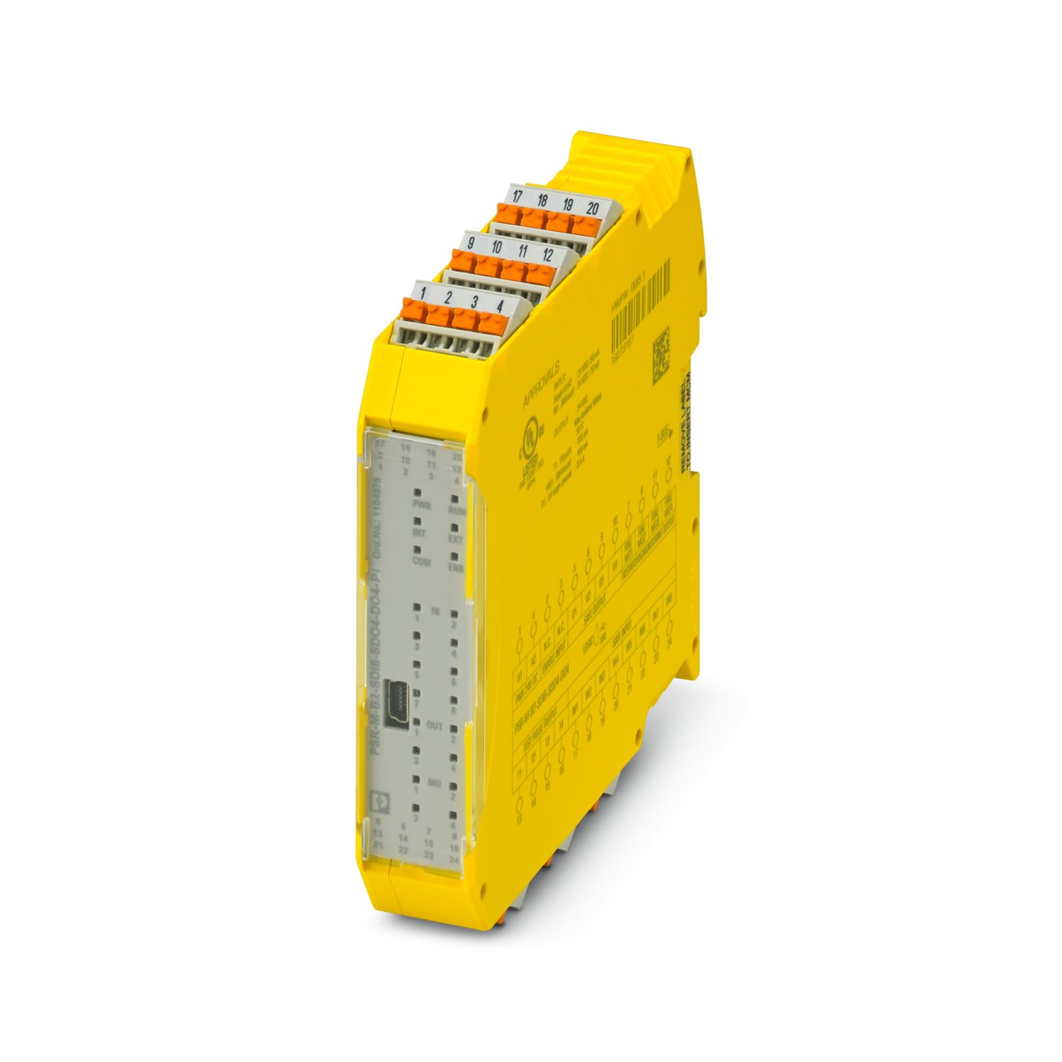
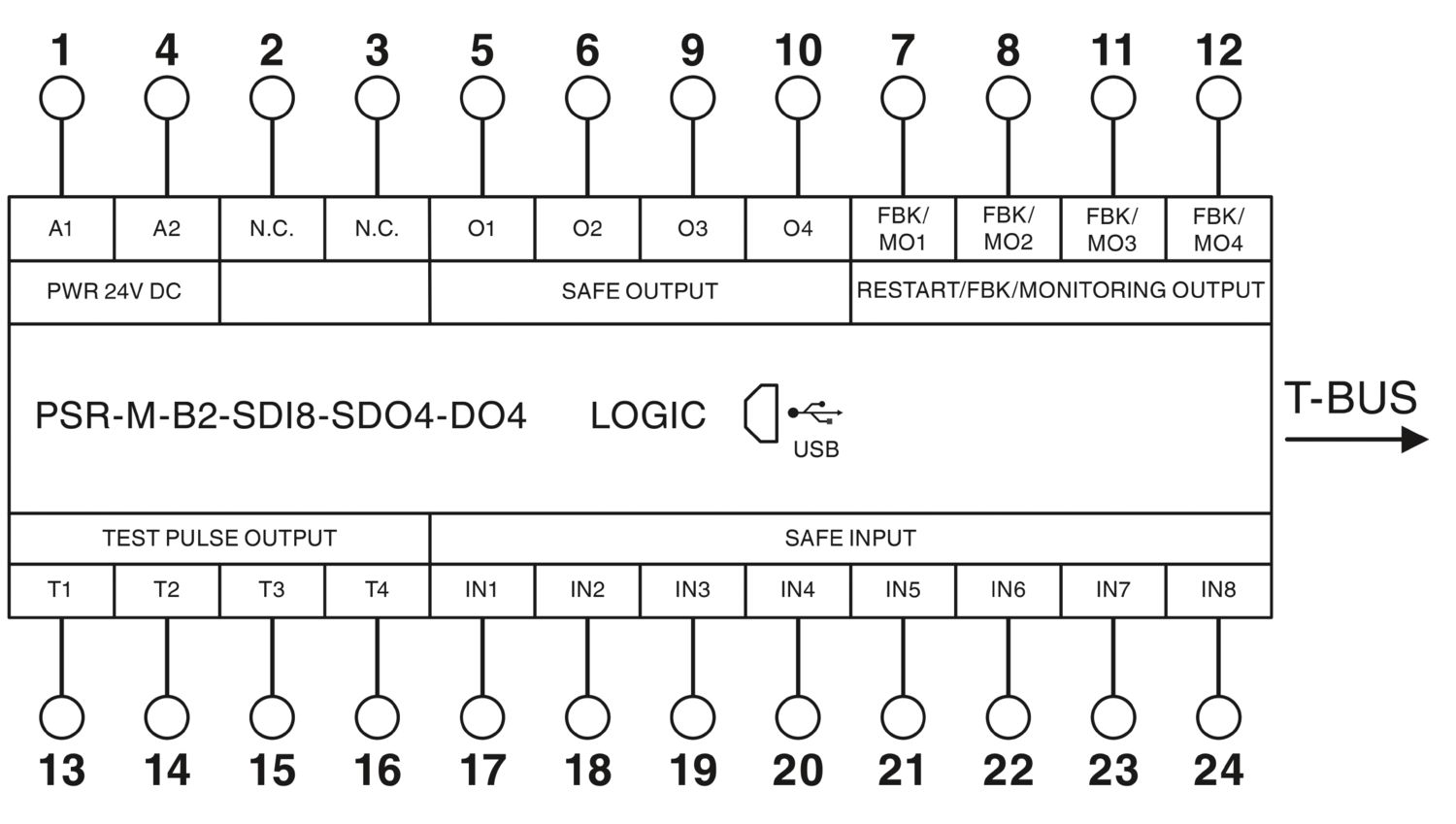
Configurable safety module (basic module), 8 safe inputs, 4 safe outputs, 4 reset inputs or 4 signal outputs, 4 clock outputs, can be extended via TBUS, up to SIL 3, Cat. 4/PL e, plug-in Push-in terminal block, TBUS connector not included

Free Download available. Downloads

Product Details


The configurable and individually scalable PSRmodular safety system is a flexible safety solution for monitoring your machine or system. The freely configurable base module is used to monitor various pieces of safety equipment such as emergency stop, safety doors, and light grids. The base module has safe inputs and outputs, as well as signal outputs and clock outputs.


Product type Safety device
Application Emergency stop
Light grid
Safety door
Safe shutdown
Insulation characteristics
Protection class III (EN 50178)
Times
Response time see user manual
Restart time min. 5 s (Boot time)
max. 10 s (Boot time)

Maximum power dissipation for nominal condition 7.1 W (with max. permissible load)
Nominal operating mode 100% operating factor
Interfaces DIN rail TBUS for connection to the master module, not supplied as standard
Air clearances and creepage distances between the power circuits
Rated insulation voltage 250 V AC
Rated surge voltage/insulation Basic insulation 4 kV between all current paths and housing
Supply
Designation A1/A2
Rated control circuit supply voltage US 19.2 V DC ... 28.8 V DC
Rated control circuit supply voltage US 24 V DC -20 % / +20 % (provide external protection, typically 5 A)
Rated control supply current IS typ. 55 mA (Outputs inactive)
typ. 135 mA (Outputs active, without load)
Power consumption at US typ. 1.32 W (Outputs inactive)
Inrush current < 2.3 A (Δt = 1 ms at Us)
Filter time typ. 5 ms (at A1 in the event of voltage dips at Us)
Protective circuit Serial protection against polarity reversal

Digital: IN1, IN2, IN3, IN4, IN5, IN6, IN7, IN8
Description of the input Safety-related digital inputs
IEC 61131-2 type 2
Number of inputs 8
Input voltage range "0" signal 0 V DC ... 5 V DC
Input voltage range "1" signal 11 V DC ... 28.8 V DC
Input current range "0" signal < 1 mA
Filter time min. 3 ms ±2 ms (adjustable)
max. 250 ms ±2 ms (adjustable)
Test pulse rate ≥ 2x set filter time, min. Test pulse rate = 10 ms
Cable length max. 100 m (per input)
Max. permissible overall conductor resistance max. 1.2 kΩ (Input and reset circuit at US)
Protective circuit Suppressor diode
Current consumption typ. 10 mA (typically with US)
max. 12.1 mA (at a control voltage of 28.8 V DC)
Digital: Reset inputs (FBK)
Description of the input configurable (as signal output or reset input)
IEC 61131-2 Type 2
Number of inputs 4
Input voltage range "0" signal 0 V DC ... 5 V DC
Input voltage range "1" signal 11 V DC ... 28.8 V DC
Input current range "0" signal < 1 mA
Filter time 250 ms ±2 ms (Test pulse rate > 500 ms)
Cable length max. 100 m (per input)
Max. permissible overall conductor resistance 1.2 kΩ (Input and reset circuit at US)
Protective circuit Suppressor diode
Current consumption typ. 12 mA (typically with US)
max. 14.7 mA (at a control voltage of 28.8 V DC)

Digital: O1, O2, O3, O4
Output description Safety-related digital outputs
PNP, OSSD
IEC 61131-2 type 0.5 (observe limiting continuous current)
Number of outputs 4
Protective circuit Suppressor diode
Short-circuit protection Yes (max. permissible short-circuit current 12 A)
Leakage current max. 250 µA
Cable length max. 100 m (per output)
Ohmic load min. 50 Ω (Observe limiting continuous current)
Max. capacitive load max. 820 nF
Max. inductive load max. 2.4 mH
Limiting continuous current 400 mA (per channel)
1.6 A (Total current of all safe digital outputs)
Inrush current max. 600 mA (Δt < 10 ms)
Nominal output voltage 24 V DC (Supply via A1)
Nominal output voltage range 18.5 V DC ... 28.1 V DC (US - 0,7 V)
Switching frequency max. 1/4 x tCycle [Hz]
Output voltage when switched off < 0.1 V
Test pulses < 120 µs (Test pulse width of low test pulses)
≥ 650 ms (Test pulse rate for low test pulse)
< 150 µs (Test pulse width, high test pulse)
≥ 1.5 s (Test pulse rate, high test pulse)
Discharging circuit Yes, internal
Signal: MO1, MO2, MO3, MO4
Output description PNP, IEC 61131-2 Typ 0,1
non-safety-related, configurable (as signal output or reset input)
Number of outputs 4
Output voltage when switched off max. 0.1 V
Voltage 24 V DC (via A1)
Maximum inrush current 1.1 A (Δt = 3 s  at Us)
Limiting continuous current 100 mA (per channel)
400 mA (Total current of all digital signal outputs)
Leakage current max. 100 µA
Switching frequency max. 1/4 x tCycle [Hz]
Protective circuit Suppressor diode
Short-circuit protection Yes (self-limitation at 1.1 A)
Cable length max. 100 m (per output)
Clock: T1, T2, T3, T4
Output description PNP, IEC 61131-2 Typ 0,1
Number of outputs 4
Voltage 24 V DC (via A1)
Output voltage when switched off max. 0.1 V
Maximum inrush current 1.1 A (Δt = 3 s  at Us)
Limiting continuous current 100 mA (per channel)
400 mA (Total current of all outputs)
Leakage current max. 100 µA
Test pulses ≤ 200 µs (Test pulse duration)
Test pulse rate = 8 x tCycle [ms]
Short-circuit protection Yes (self-limitation at 1.1 A)
Cable length max. 100 m (per output)
Max. capacitive load max. 470 nF
Max. inductive load max. 2.4 mH
Discharging circuit Yes, internal

Connection technology
pluggable yes
Conductor connection
Connection method Push-in connection
Conductor cross section solid 0.2 mm² ... 2.5 mm²
Conductor cross section flexible 0.2 mm² ... 2.5 mm²
Conductor cross-section AWG 24 ... 16
Stripping length 10 mm

Status display 1 x LED (green), 1 x LED (orange), 1 x LED (blue)
4 x LED (green, yellow, red)
12 x LED (yellow)
Operating voltage display 1 x green LED
Error indication 2 x LED (red)

Width 22.61 mm
Height 107.74 mm
Depth 113.6 mm

Housing material Polyamide PA non-reinforced

Safety data
Stop category 0
Safety data: EN ISO 13849
Performance level (PL) e (2-channel wiring)
d (1-channel wiring)
Safety data: IEC 61508 - High-demand for 2-channel wiring
Equipment type Type B
Safety Integrity Level (SIL) 3
Probability of a hazardous failure per hour (PFHD) 1.35 x 10⁻⁸
Proof test interval 240 Months
Duration of use 240 Months
Integrity requirement IEC 61508 - High-demand for 1-channel wiring
Equipment type Type B
Safety Integrity Level (SIL) 2
Probability of a hazardous failure per hour (PFHD) 1.35 x 10⁻⁸
Proof test interval 240 Months
Duration of use 240 Months

Ambient conditions
Degree of protection IP20
Min. degree of protection of inst. location IP54
Ambient temperature (operation) -10 °C ... 55 °C (observe derating)
Ambient temperature (storage/transport) -20 °C ... 85 °C
Maximum altitude ≤ 2000 m (Above sea level)
Max. permissible humidity (storage/transport) 95 % (non-condensing)
Max. permissible relative humidity (operation) 95 % (non-condensing)
Shock 10g for Δt = 16 ms (continuous shock, 1000 shocks in each space direction)
Vibration (operation) 10 Hz ... 150 Hz, 2g

CE
Certificate CE-compliant

Air clearances and creepage distances between the power circuits
Standards/regulations EN 50178

Mounting type DIN rail mounting
Assembly instructions Observe derating
Mounting position vertical or horizontal

Item number 1104975
Packing unit 1 pc
Minimum order quantity 1 pc
Sales Key DNA361
Product Key DNA361
GTIN 4055626974750
Weight per Piece (including packing) 185.33 g
Weight per Piece (excluding packing) 141 g
Customs tariff number 85371098
Country of origin IT


ECLASS

ECLASS-9.0 27371819
ECLASS-10.0.1 27371819
ECLASS-11.0 27371819

ETIM

ETIM 8.0 EC001449

UNSPSC

UNSPSC 21.0 39122200

UL Listed

Approval ID: FILE E 238705

cUL Listed

Approval ID: FILE E 238705

EAC

Approval ID: RU*-DE*B.00606/20

Functional Safety

Approval ID: Z10 029429 0013

cULus Listed


China RoHS Environmentally friendly use period: unlimited = EFUP-e
No hazardous substances above threshold values

Your advantages

Cost-effective safety solution with a high level of adaptability to individual requirements
Fast startup, thanks to easy hardware and software configuration
Machine downtimes minimized with comprehensive, easy-to-understand diagnostics
Flexible extension with safe inputs and outputs
Possibility of connecting fieldbus gateways for bidirectional communication between the base module and the higher-level controller
Narrow housing width of just 22.6 mm
Tool-free and time-saving installation thanks to Push-in technology
Up to Cat. 4/PL e in accordance with EN ISO 13849-1, SIL 3 in accordance with IEC 62061, SIL 3 in accordance with IEC 61508
Suitable for elevator applications in accordance with EN 81-20