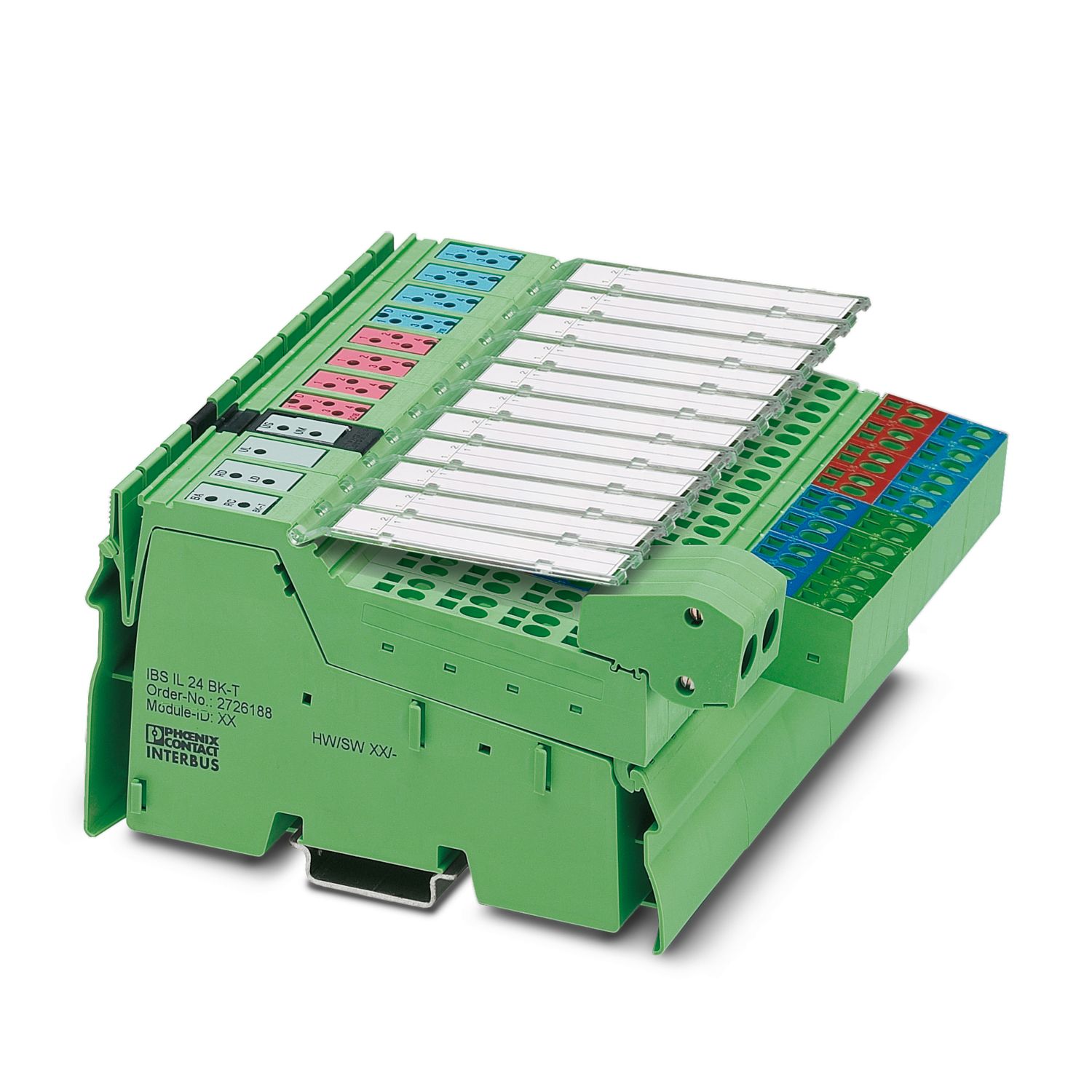
The complete Inline station consists of an INTERBUS bus terminal, a digital output terminal with 16 outputs, and a digital input terminal with 16 inputs. This package contains all the necessary Inline connector to connect the bus, the supply and the I/Os.
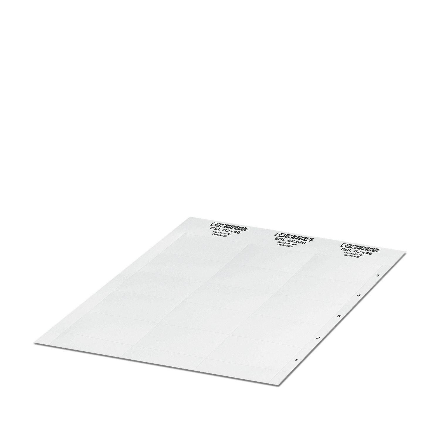
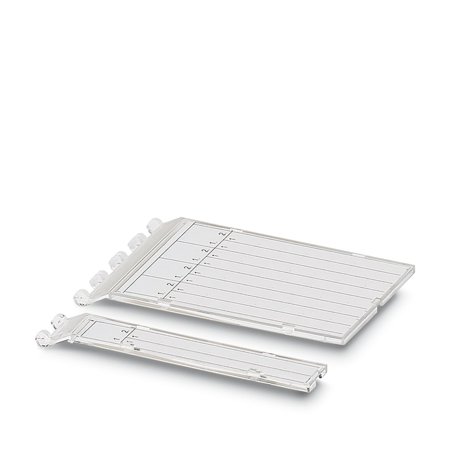
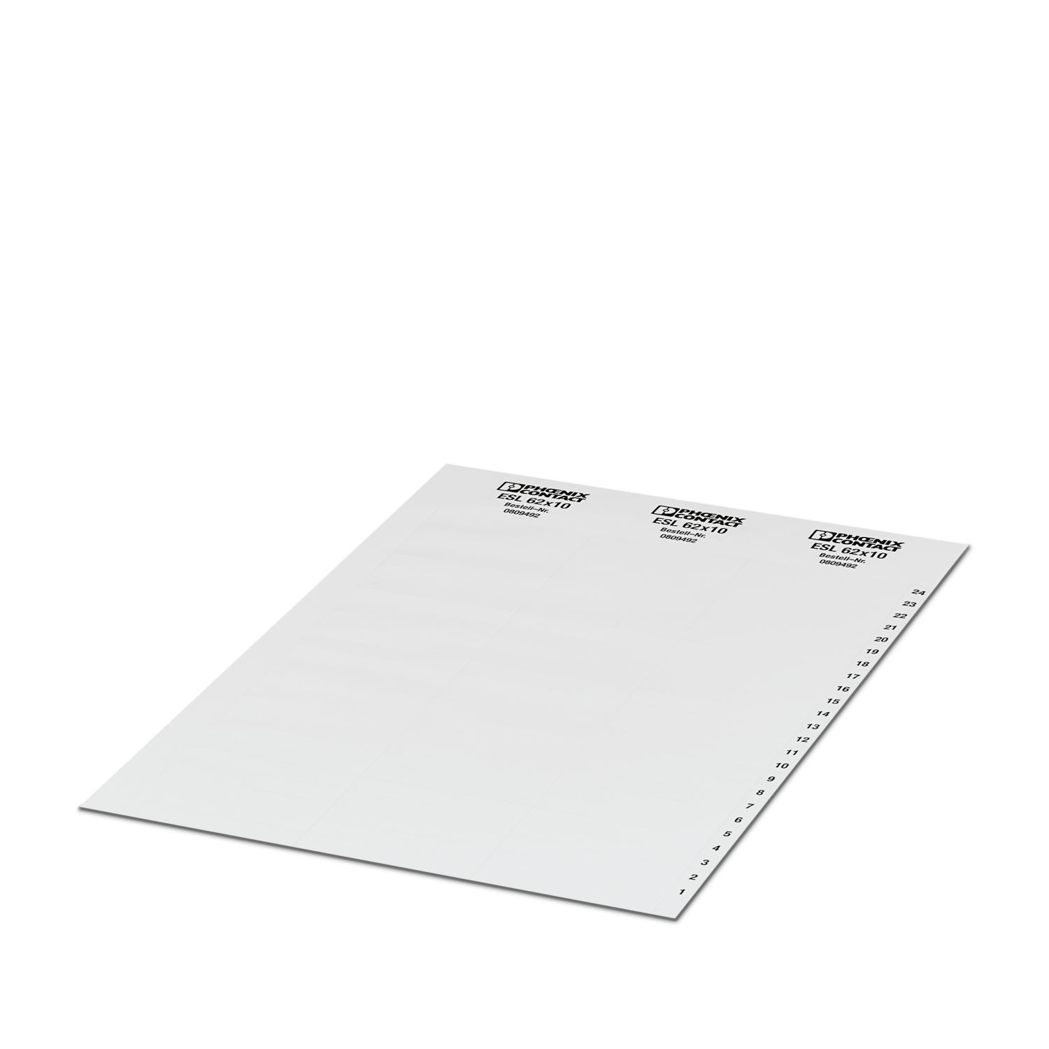
The Inline terminals can be labeled using hinged labeling fields. The fields have insert cards that can be labeled individually to suit the application. Additionally, there is the ZBFM -6... Zack strip for labeling the terminal points.
IBS IL 24 BK DIO 16/16
-
Bus coupler
2742586
Inline, Bus coupler, INTERBUS, Inline shield connector, Digital inputs: 16, 24 V DC, connection technology: 3-conductor, Digital outputs: 16, 24 V DC, 500 mA, connection technology: 3-conductor, transmission speed in the local bus: 500 kbps, degree of protection: IP20, including Inline connectors and marking fields
Product details
| Dimensional drawing |
|
| Width | 146.4 mm |
| Height | 140.5 mm |
| Depth | 71.5 mm |
| Note on application | |
| Note on application | Only for industrial use |
| Utilization restriction | |
| EMC note | EMC: class A product, see manufacturer's declaration in the download area |
| Color (Housing) | green (RAL 6021) |
| INTERBUS | |
| Number of interfaces | 2 |
| Connection method | Inline shield connector |
| Transmission speed | 500 kbps |
| Inline local bus | |
| Number of interfaces | 1 |
| Connection method | Inline data jumper |
| Transmission speed | 500 kbps |
| System limits | |
| Number of local bus devices that can be connected | 63 (observe total permissible current consumption) |
| Number of devices with parameter channel | 16 |
| Number of supported branch terminals with remote bus branch | max. 15 |
| Programming data | |
| Register length (bus) | 32 bit |
| Register length (master) | 8192 bit |
| Digital: | |
| Input name | Digital inputs |
| Description of the input | EN 61131-2 type 1 |
| Number of inputs | 16 |
| Connection method | Spring-cage connection |
| Connection technology | 3-conductor |
| Input voltage | 24 V DC |
| Input voltage range "1" signal | 15 V DC ... 30 V DC |
| Nominal input voltage UIN | 24 V DC |
| Typical input current per channel | typ. 3 mA |
| Protective circuit | Polarity reversal; Suppressor diode |
| Digital: | |
| Output name | Digital outputs |
| Connection method | Spring-cage connection |
| Connection technology | 3-conductor |
| Number of outputs | 16 |
| Protective circuit | Short-circuit and overload protection; Free running circuit |
| Output voltage | 24 V DC -1 V (At nominal current) |
| Max. current carrying capacity per output | max. 500 mA |
| Maximum output current per module | max. 8 A |
| Nominal output voltage | 24 V DC |
| Nominal load, inductive | 12 VA |
| Nominal load, lamp | 12 W |
| Nominal load, ohmic | 12 W |
| Product type | I/O component |
| Product family | Inline |
| Type | modular |
| Scope of supply | including Inline connectors and marking fields |
| No. of channels | 32 |
| Maximum power dissipation for nominal condition | 8 W |
| Protective circuit | Reverse polarity protection |
| Potentials: Bus coupler supply UBK; Communications power UL (7.5 V) and the analog supply UANA (24 V) are generated from the bus coupler supply. | |
| Supply voltage | 24 V DC (via Inline connector) |
| Supply voltage range | 19.2 V DC ... 30 V DC (including all tolerances, including ripple) |
| Current draw | max. 1.25 A (with max. number of connected I/O terminal blocks (24 V DC supply)) |
| typ. 100 mA (without connected Inline I/O terminals) | |
| Potentials: Communications power (UL) | |
| Supply voltage | 7.5 V DC ±5 % |
| Power supply | max. 2 A DC |
| Potentials: Supply of analog modules (UANA) | |
| Supply voltage | 24 V DC |
| Supply voltage range | 19.2 V DC ... 30 V DC (including all tolerances, including ripple) |
| Power supply | max. 0.5 A DC (observe derating) |
| Potentials: Main circuit supply (UM) | |
| Supply voltage | 24 V DC |
| Supply voltage range | 19.2 V DC ... 30 V DC (including all tolerances, including ripple) |
| Power supply | max. 8 A DC (sum of UM + US) |
| Potentials: Segment circuit supply (US) | |
| Supply voltage | 24 V DC (via voltage jumper) |
| Supply voltage range | 19.2 V DC ... 30 V DC (including all tolerances, including ripple) |
| Power supply | max. 8 A DC (sum of UM + US) |
| Electrical isolation/isolation of the voltage ranges | |
| Test voltage: 5 V supply, incoming remote bus / 5 V supply outgoing remote bus | 500 V AC, 50 Hz, 1 min |
| Test voltage: 5 V supply incoming remote bus / 7.5 V communications power, 24 V analog supply, 24 V bus coupler supply | 500 V AC, 50 Hz, 1 min |
| Test voltage: 5 V supply, incoming remote bus / 24 V main supply, 24 V segment supply | 500 V AC, 50 Hz, 1 min |
| Test voltage: 5 V supply incoming remote bus / functional ground | 500 V AC, 50 Hz, 1 min |
| Test voltage: 5 V supply outgoing remote bus / communications power (UBK, UL, UANA) | 500 V AC, 50 Hz, 1 min |
| Test voltage: 5 V supply outgoing remote bus / I/O (UM, US) | 500 V AC, 50 Hz, 1 min |
| Test voltage: 5 V supply outgoing remote bus / functional ground | 500 V AC, 50 Hz, 1 min |
| Test voltage: 7.5 V communications power, 24 V analog supply, 24 V bus coupler supply/functional ground | 500 V AC, 50 Hz, 1 min |
| Test voltage: 7.5 V logics supply, 24 V analog supply, 24 V bus terminal module supply / 24 V main supply, 24 V segment supply | 500 V AC, 50 Hz, 1 min |
| Test voltage: 24 V main supply, 24 V segment supply/functional ground | 500 V AC, 50 Hz, 1 min |
| Connection technology | |
| Connection name | Inline connector |
| Inline connector | |
| Connection method | Spring-cage connection |
| Conductor cross-section, rigid | 0.08 mm² ... 1.5 mm² |
| Conductor cross-section, flexible | 0.08 mm² ... 1.5 mm² |
| Conductor cross-section AWG | 28 ... 16 |
| Stripping length | 8 mm |
| Ambient conditions | |
| Ambient temperature (operation) | -25 °C ... 55 °C |
| Degree of protection | IP20 |
| Air pressure (operation) | 80 kPa ... 106 kPa (up to 3000 m above sea level) |
| Air pressure (storage/transport) | 70 kPa ... 106 kPa (up to 3000 m above sea level) |
| Permissible humidity (operation) | 95 % (non-condensing) |
| Permissible humidity (storage/transport) | 95 % (non-condensing) |
| Mechanical test | |
| Vibration resistance in accordance with EN 60068-2-6/IEC 60068-2-6 | 5g |
| Shock in accordance with EN 60068-2-27/IEC 60068-2-27 | Operation: 25g, 11 ms duration, semi-sinusoidal shock impulse |
| Mounting type | DIN rail mounting |
| Item number | 2742586 |
| Packing unit | 1 pc |
| Minimum order quantity | 1 pc |
| Sales key | D23 |
| Product key | DRI111 |
| GTIN | 4017918603984 |
| Weight per piece (including packing) | 710.9 g |
| Weight per piece (excluding packing) | 394 g |
| Customs tariff number | 85389091 |
| Country of origin | DE |
ECLASS
| ECLASS-13.0 | 27242608 |
ETIM
| ETIM 9.0 | EC001604 |
UNSPSC
| UNSPSC 21.0 | 32151600 |
| EU RoHS | |
| Fulfills EU RoHS substance requirements | Yes |
| Exemption | 7(a), 7(c)-I |
| China RoHS | |
| Environment friendly use period (EFUP) |
EFUP-50
An article-related China RoHS declaration table can be found in the download area for the respective article under "Manufacturer declaration". For all articles with EFUP-E, no China RoHS declaration table issued and required.
|
| EU REACH SVHC | |
| REACH candidate substance (CAS No.) | Lead (CAS: 7439-92-1) |
| SCIP | f1954fae-d152-4898-a18a-e5cf7d1b9838 |
Compatible products
Your advantages
16 digital inputs
16 digital outputs
Connection of sensors in 2- and 3-conductor technology
Connection of actuators in 2- and 3-conductor technology
Maximum permissible load current per sensor: 250 mA
Nominal current per output: 500 mA
Diagnostic and status indicators
PHOENIX CONTACT Ltd
8240 Parkhill Drive, Milton, Ontario L9T 5V7