Intrinsically safe circuits in measurement and control technology The intrinsic safety (Ex i) type of protection is established worldwide in the field of measurement and control technology in potentially explosive areas. Learn more about designing intrinsically safe circuits here.

What is an intrinsically safe circuit?

Components of an intrinsically safe circuit
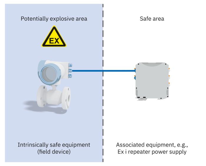
An intrinsically safe circuit consists of at least one item of intrinsically safe equipment and one item of associated equipment and connecting cables. Intrinsically safe equipment may only be connected to circuits without intrinsic safety via associated equipment.
Associated equipment has both intrinsically safe circuits and non-intrinsically safe circuits. The isolation is via Zener barriers or electrical isolators. Intrinsically safe equipment is classified in accordance with IEC/EN 60079-11 in the protection levels ia, ib, and ic.

Protection principle of Ex i type of protection
The protection principle behind the Ex bi type of protection is based on limiting the energy that is conducted to the potentially explosive area and is stored there. This means that the energy from any potential spark must always be less than the minimum ignition energy of the surrounding potentially explosive atmosphere.
The Ex i type of protection refers to the entire intrinsically safe circuit in accordance with IEC/EN 60079-11.
The voltage is limited in order to keep the spark energy below the ignition energy. The current is limited to prevent thermal effects due to surfaces that are too hot.
Basic circuit diagram for limiting voltage and current
- Voltage limitation: The Zener diode becomes conductive at a defined voltage value and limits the voltage.
- Current limitation: A resistor connected in series limits the maximum current.
Designing intrinsically safe circuits
Testing the suitability of the device based on the marking
To ensure that the intrinsically safe circuit is safe, the operator must carry out and implement the measures for evaluating the suitability of the equipment with regard to the required level of protection and the available material groups, to proof of intrinsic safety, right through to installation. Based on the risk analysis, the operator must determine the zone, group, and temperature class for the field device and check the approval of the devices for the application. This can be done, for example, by means of the equipment marking in accordance with the table.
Note: here, “EX” stands for the use of the Ex symbol
|
Intrinsically safe equipment (field device):
EX II 1 G Ex ia IIB T6 Ga |
Evaluation of the Ex mark |
Associated equipment
EX II (1) G [Ex ia Ga] IIC |
|
|---|---|---|---|
| -a) | … 1 … Ga | Equipment category / Equipment protection level of the Ex i field device correspond to the specified zone | |
| b) | … 1 … ia … Ga | Type of protection of the Ex i field device is permitted in the specified zone | |
| c) | … 1 G … IIB T6 …. | The Ex i field device is permitted in the existing gas atmosphere | |
| d) | Associated marking of equipment with brackets, without specifying the temperature class/limits | … (1) … [ … ] … | |
| e) | … 1 G … Ga | Equipment category / Equipment protection level of the associated equipment corresponds to Ex i field device | … (1) G [ … Ga] … |
| f) | … Ex ia … | Type of protection of the associated equipment matches that of the Ex i field device | … [Ex ia … ] … |
| g) | … IIB … | The associated equipment is approved for the same group or one of a higher order | … IIC |

Proof of intrinsic safety
The intrinsically safe circuit typically consists of the intrinsically safe equipment, the associated equipment, and the connecting cables. To ensure that the device combination is safe, testing must be performed on the corresponding circuit to prove its intrinsic safety. This must be done in accordance with IEC/EN 60079-14 and, where necessary, other standards and regulations.
Proof of intrinsic safety for intrinsically safe circuits with one source of electricity
Most intrinsically safe circuits have just one energy source or one item of equipment. First, the criteria are checked in accordance with the table “Checking the suitability of the device using the marking”. Operating instructions provide the necessary safety data. The voltage, current, power, capacity, and inductance parameters are then checked.
For proof of intrinsic safety, the cable capacities and inductances can be found in the data sheets of the cables. Alternatively, the following worst-case specifications can be assumed in accordance with IEC/EN 60079-14:
- Cable capacitance: 200 nF/km
- Cable inductance: 1 mH/km
The parameters specified by the cable manufacturers are usually lower.
Conditions for fulfilling proof of intrinsic safety
If the five conditions are met, the combination of equipment, associated equipment, and conductors is intrinsically safe.
|
Intrinsically safe equipment (field device)
EX II 1 G Ex ia IIB T6 Ga |
Connecting cables |
Associated equipment
EX II (1) G [Ex ia Ga] IIC |
|
|---|---|---|---|
| 1) | Ui | ≥ Uo | |
| 2) | Ii | ≥ Io | |
| 3) | Pi | ≥ Po | |
| 4) | Ci | + Cc | ≤ Co |
| 5) | Li | + Lc | ≤ Lo |
Example for proof of intrinsic safety: Analog IN

Ex i repeater power supply
The device transmits analog 4 … 20 mA signals from a passive measuring transducer from the Ex area to a controller and supplies the measuring transducer with power.
Comparison of the safety data Example of analog IN
Assumption: Cc= 180 nF/km, Lc= 1 mH/km
|
Intrinsically safe equipment (field device)
Pressure transmitter |
Connecting cables
Length = 500 m |
Associated equipment
MACX MCR-EX-RPSSI-I Ex i repeater power supply |
Condition fulfilled? | |
|---|---|---|---|---|
| 1) | Ui = 30 V | ≥ Uo = 25.2 V | yes | |
| 2) | Ii = 100 mA | ≥ Io = 93 mA | yes | |
| 3) | Pi = 750 mW | ≥ Po = 587 mW | yes | |
| 4) | Ci = 0 nF | + Cc = 90 nF | ≤ Co = IIC: 107 nF | yes |
| 5) | Li = 0 mH | + Lc = 0.5 mH | ≤ Lo = IIC: 3 mH | yes |
Summary: The conditions for proof of intrinsic safety are met.
Example for proof of intrinsic safety: Analog OUT

Ex i output signal conditioner
The device transmits analog 0/4 … 20 mA signals from a controller to an actuator in the Ex area in an electrically isolated manner.
Comparison of the safety data Example of analog OUT
Assumption: Cc= 180 nF/km, Lc= 1 mH/km
|
Intrinsically safe equipment
Control valve |
Connecting cables
Length = 250 m |
Associated equipment
MINI MCR-EX-IDS-I-I-PT Ex i output signal conditioner |
Condition fulfilled? | |
|---|---|---|---|---|
| 1) | Ui = 28 V | ≥ Uo = 26.4 V | yes | |
| 2) | Ii = 110 mA | ≥ Io = 98 mA | yes | |
| 3) | Pi = 770 mW | ≥ Lo = 647 mW | yes | |
| 4) | Ci = 5 nF | + Cc = 45 nF | ≤ Co = IIC: 89 nF | yes |
| 5) | Li = 0 mH | + Li = 0.25 mH | ≤ Lo = IIC: 2 mH | yes |
Summary: The conditions for proof of intrinsic safety are met.
Installation of electrical devices for signal transmission in the Ex area
Application requirements for electrical equipment
Electrical equipment operated in systems with Ex areas is subject to different usage requirements. The following cases may be applicable for MCR technology:
- Sensors and actuators are distributed in all Ex zones
- Signal conditioners are located in Zone 1, Zone 2, or in the safe area
- The controller is generally in the safe area
The instrumentation can be done in accordance with intrinsic safety type and/or in a different type of protection.
Intrinsically safe signal transmission in potentially explosive areas
Sensors and actuators in Zone 0 are usually installed with intrinsic safety Ex ia protection and connected to the associated equipment. The safety-related data is specified in the EU type test certificate for the Ex i isolator.
Ex i isolators may only be installed outside of the potentially explosive area, unless they are protected by another type of protection such as a flameproof enclosure:
• Installation in Zone 1, e.g., in flameproof enclosure
• Installation in Zone 2, e.g., in combination with increased safety: the conditions of IEC 60079-15 must be met here, e.g., housings must have a degree of protection of at least IP54.
Non-intrinsically safe signal transmission in a potentially explosive area
If sensors or actuators are present in other types of protection such as Ex d or Ex e, the use of non-intrinsically safe isolators is permitted. Devices in Zone 2 require Ex ec approval that prescribes special conditions such as an approved housing in accordance with IEC/EN 60079-15 and IEC/EN 60079-0 with at least a degree of protection of IP54. Without this approval, the isolators must be installed in a flameproof housing (Ex dc).
An “ec” sensor/actuator can be connected to an intrinsically safe isolator or a non-intrinsically safe isolator in Zone 2. When connected to an Ex i isolator, intrinsic safety is no longer applicable; the isolator must be marked accordingly.
Installation requirements
The figure shows various installation options for electrical devices in areas with a danger of gas explosions. Requirements on configuration, selection, and installation are included in IEC/EN 60079-14. Requirements on testing, maintenance, and repair are specified in IEC/EN 60079-17 and IEC/EN 60079-19.


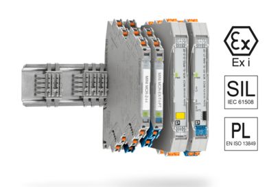
Signal conditioners and measuring transducers for explosion protection
In addition to the standard functions, signal conditioners and measuring transducers for explosion protection guarantee electrical explosion protection for all substance groups and areas in accordance with the relevant standards. The products are developed and evaluated consistently in accordance with SIL IEC 61508 and PL DIN EN ISO 13849. As a result, they minimize dangers to an acceptable residual risk and ensure the protection of people, machines, and the environment.


