
PT-IQ-1X2+F-24DC-UT
-
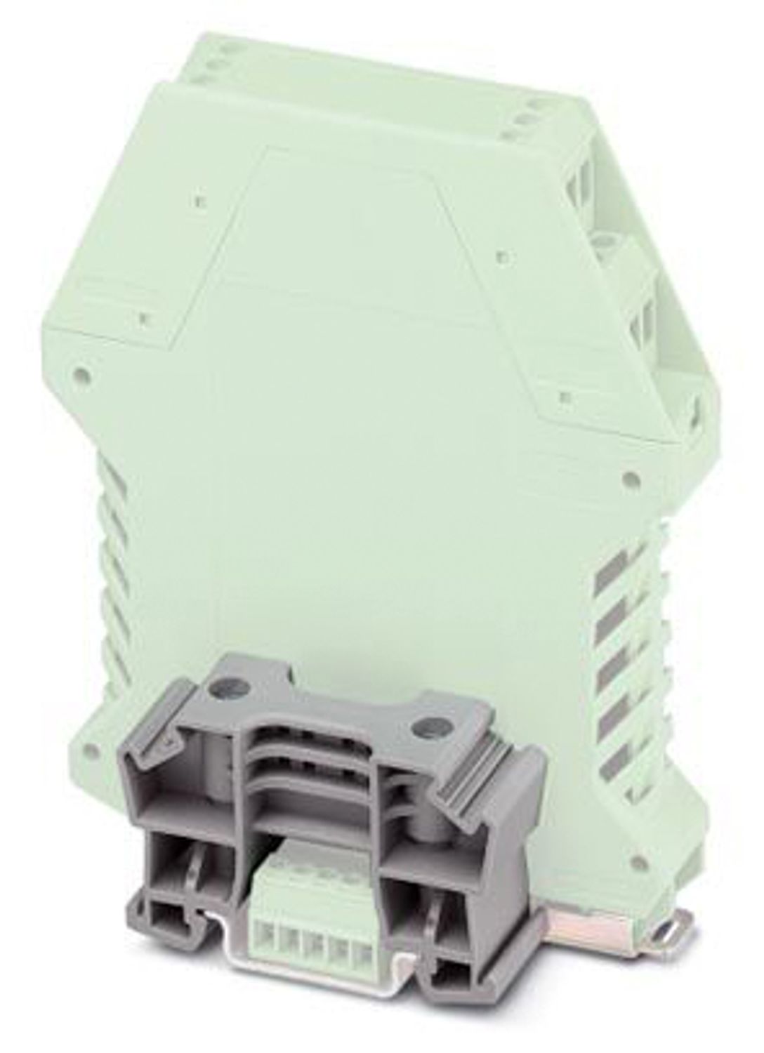
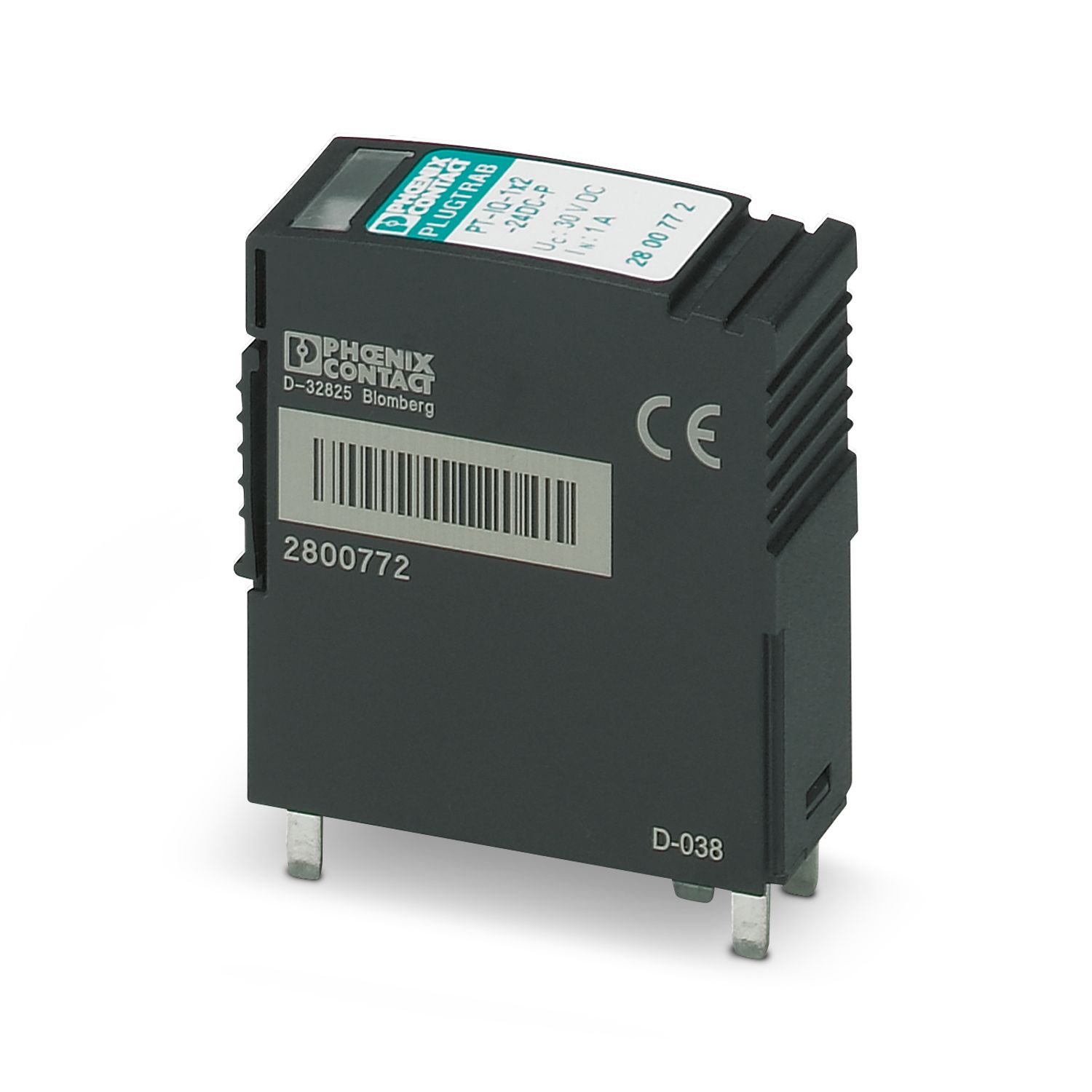
Surge protection device
2800977
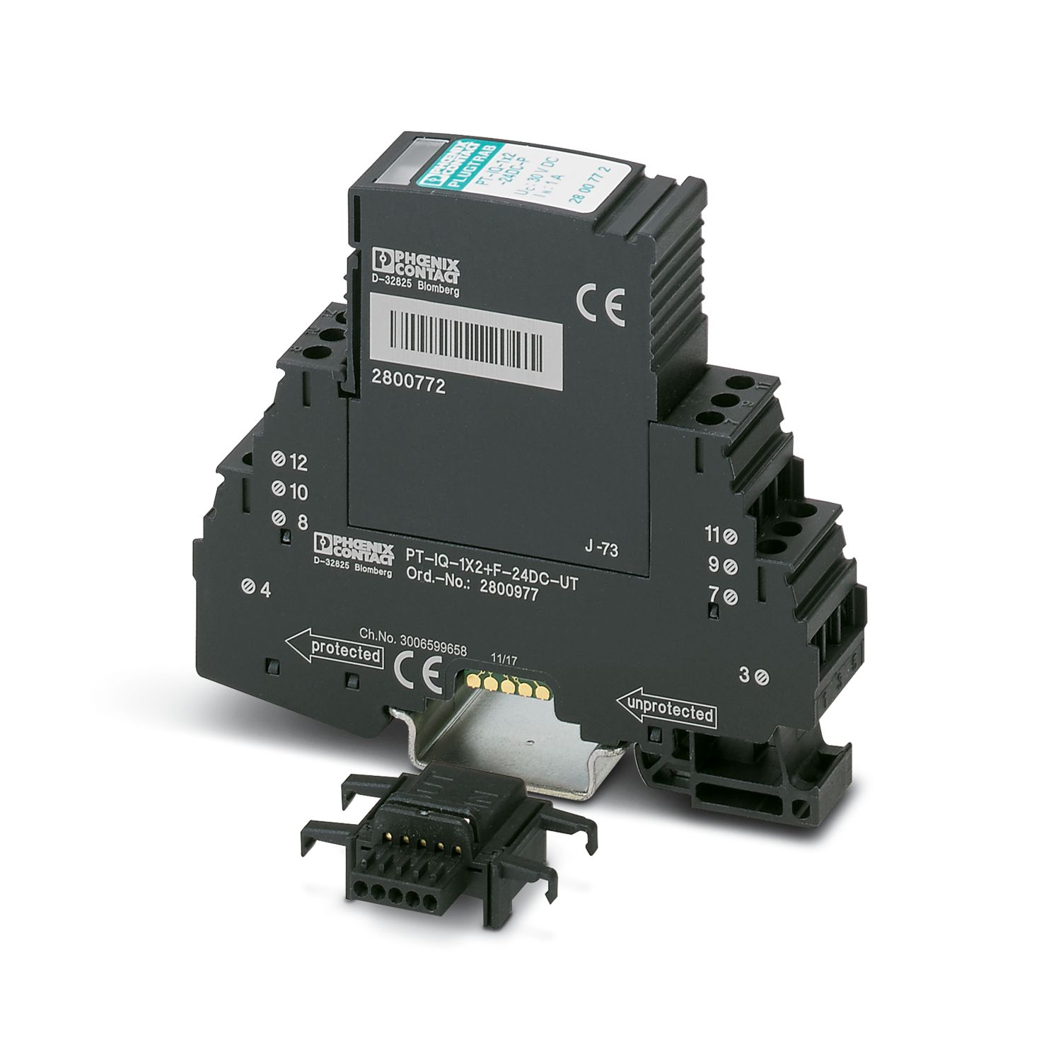
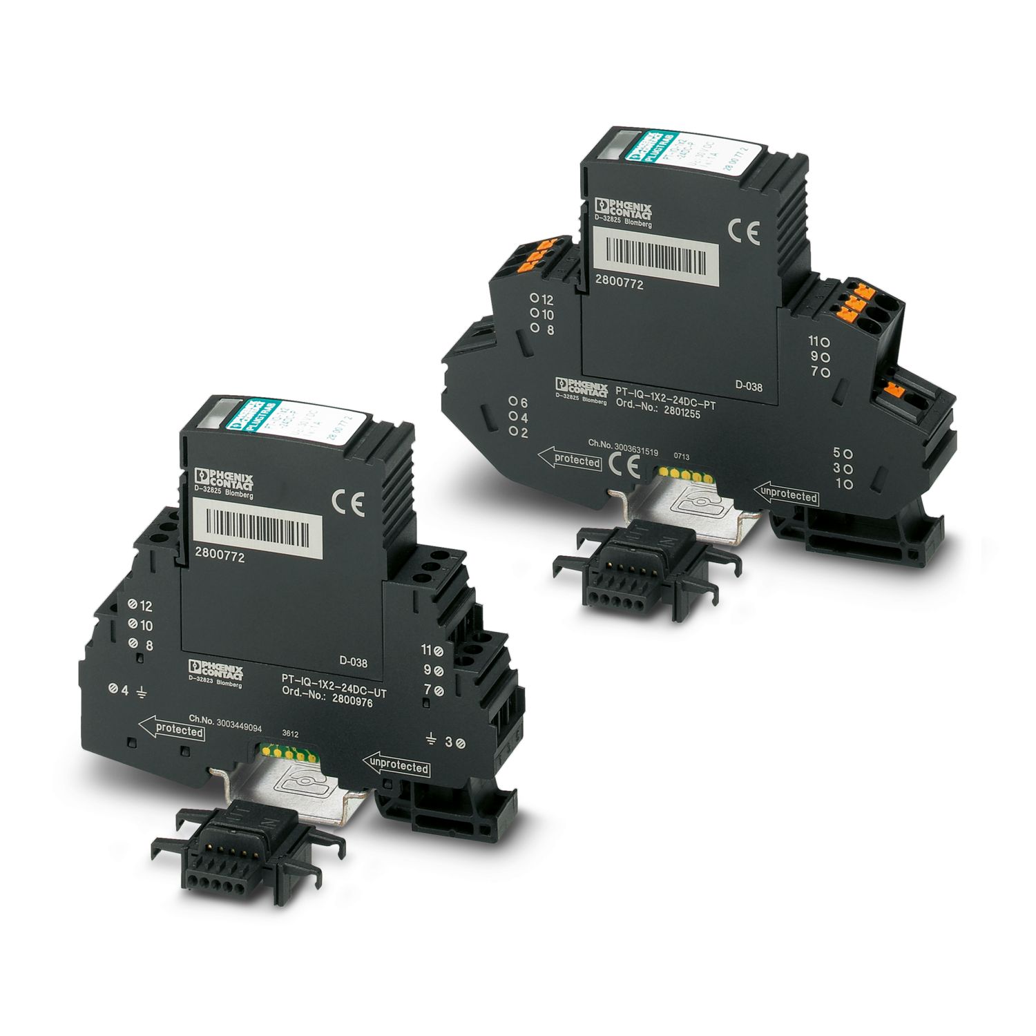
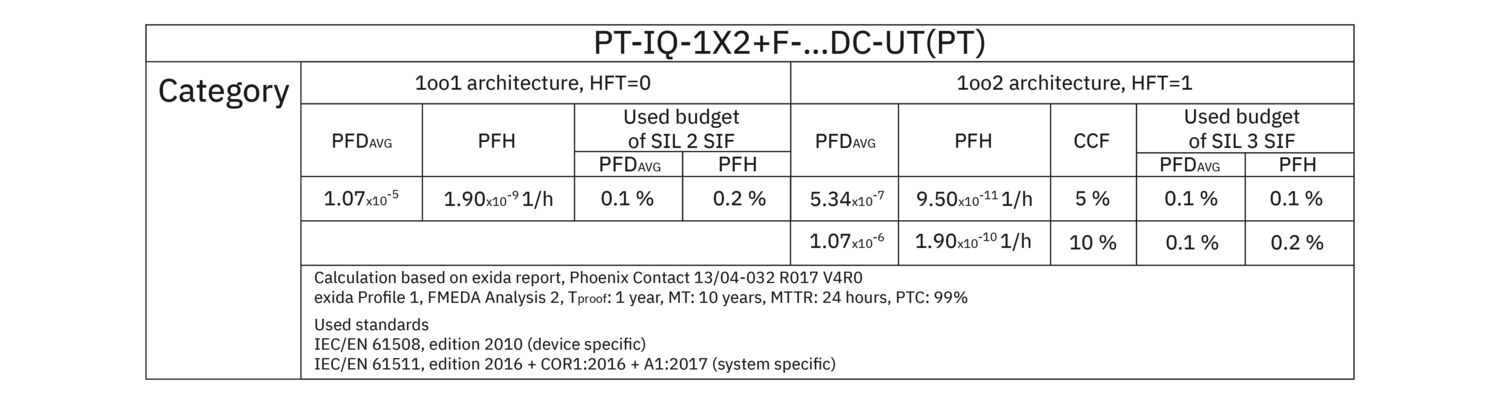
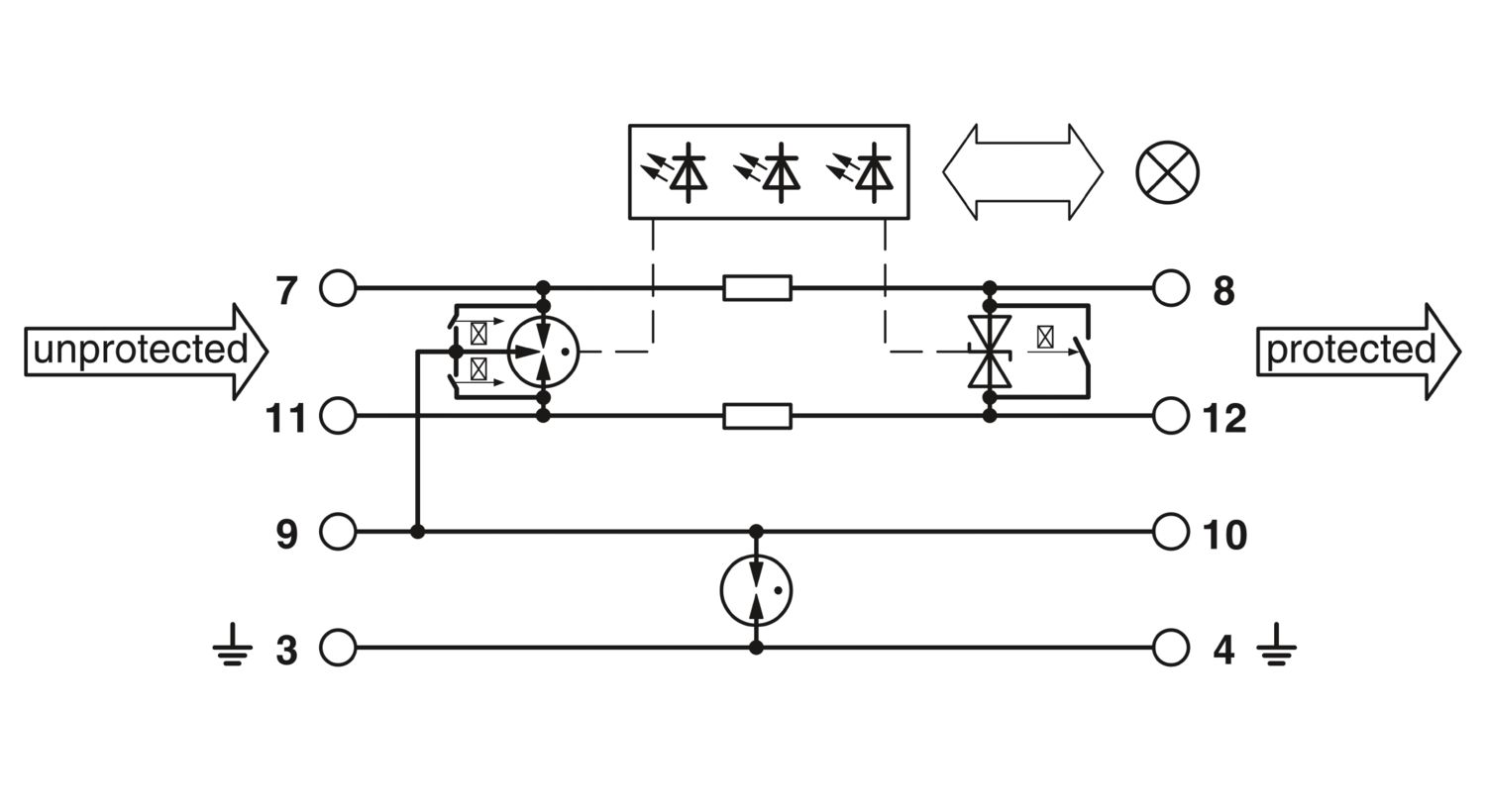
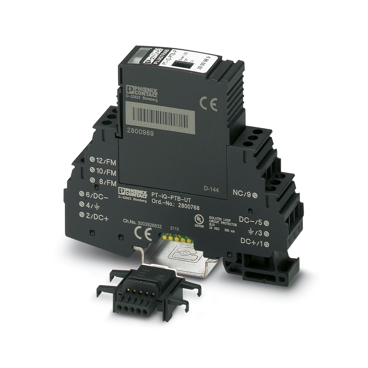
Surge protection, consisting of protective plug and base element, with integrated multi-stage status indicator on the module, for one 2-wire floating signal circuit. Indirect grounding via gas discharge tube. Can be used in safety-related circuits up to SIL 3.
This product needs further products for operation.
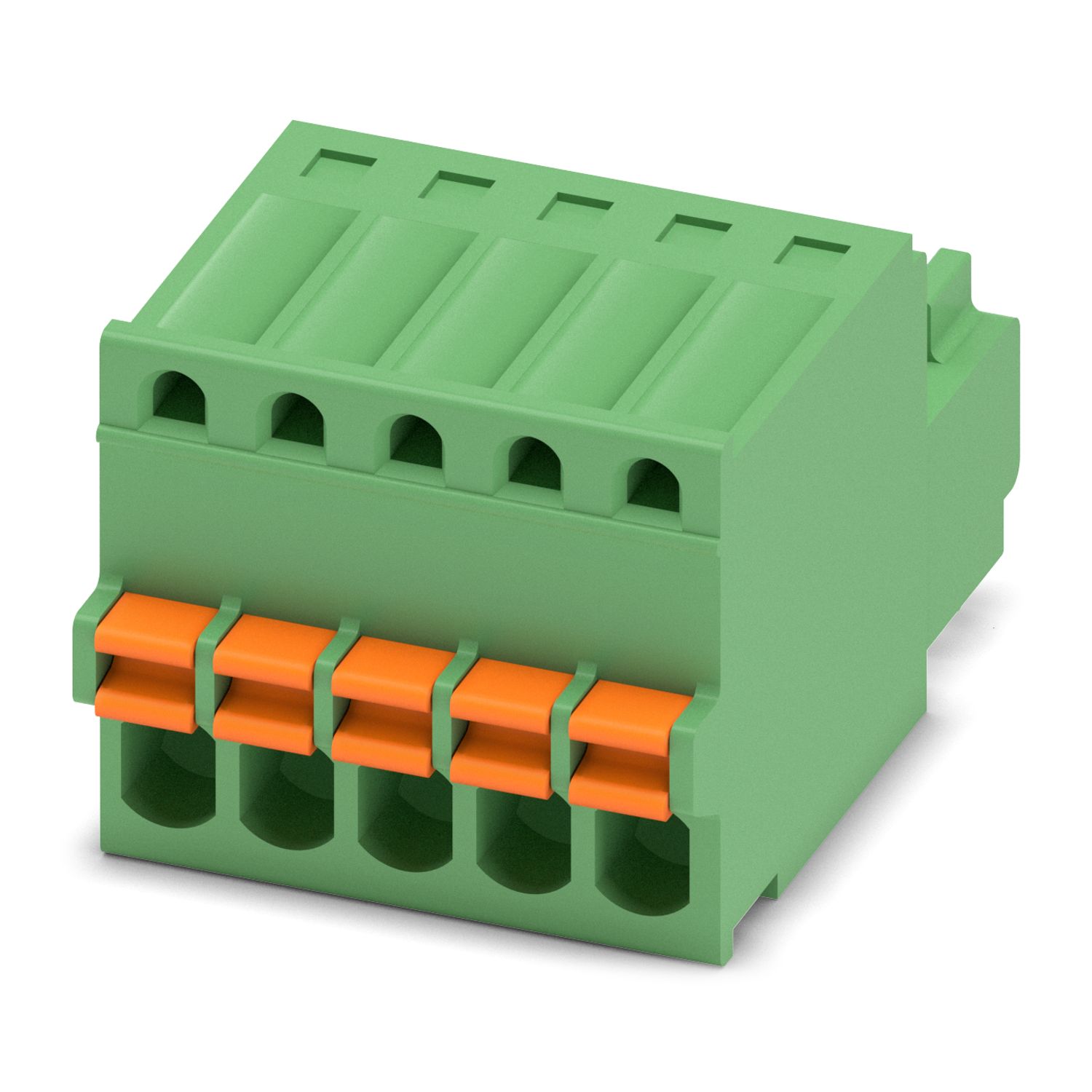
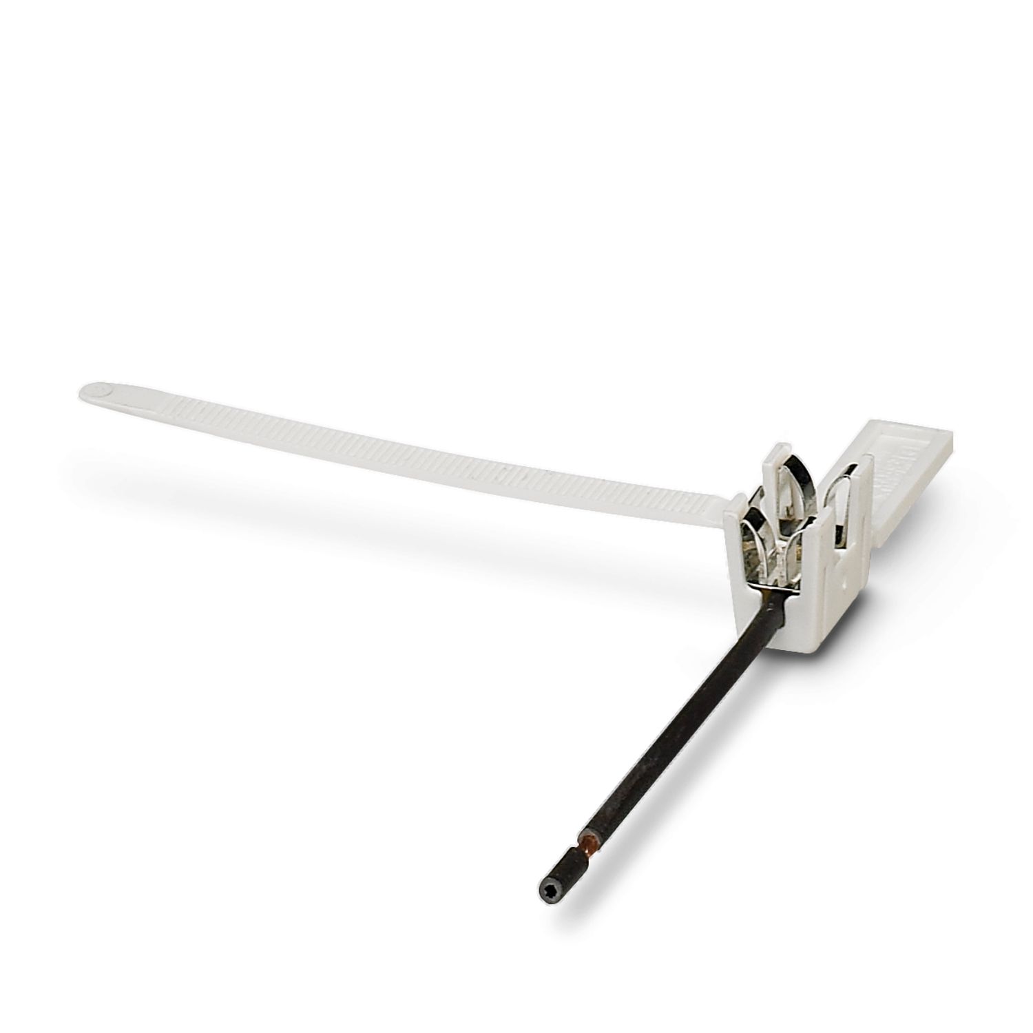
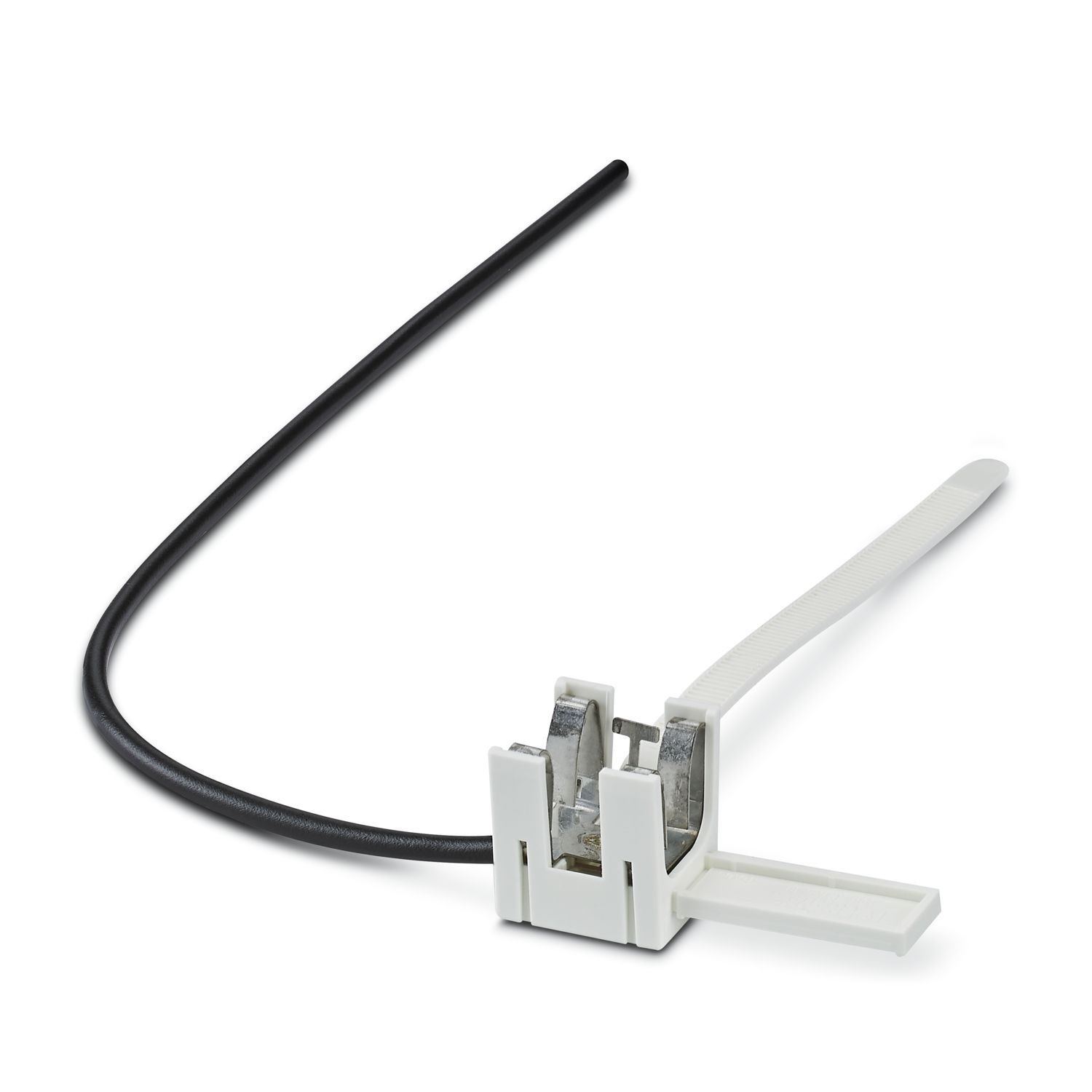
Mandatory accessories
Product details
| General | |
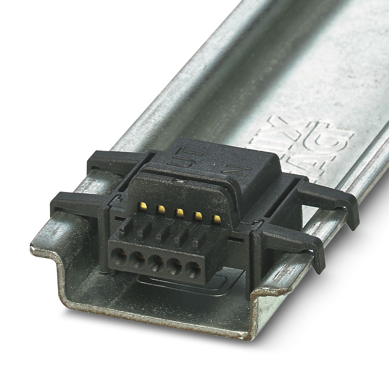
| Note | Remote signaling as well as the power supply of the DIN rail connector are established by snapping the module into place on the DIN rail connector. |
| Product family | PLUGTRAB IQ |
| IEC test classification | C1 |
| C2 | |
| C3 | |
| D1 | |
| Type | DIN rail module, two-section, divisible |
| Surge protection fault message | Optical, multi-stage |
| Wire pairs per module | 1 |
| Insulation characteristics | |
| Overvoltage category | III |
| Pollution degree | 2 |
| Nominal voltage UN | 24 V DC |
| Connection method | Screw connection |
| Screw thread | M3 |
| Tightening torque | 0.5 Nm |
| Conductor cross-section flexible | 0.2 mm² ... 2.5 mm² |
| Conductor cross-section rigid | 0.2 mm² ... 4 mm² |
| Conductor cross-section AWG | 24 ... 12 |
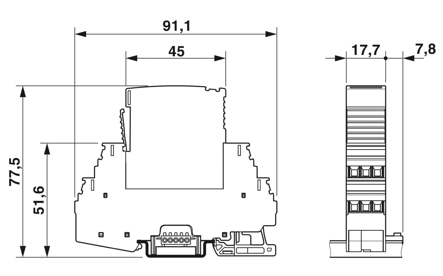
| Dimensional drawing |
|
| Width | 17.7 mm |
| Height | 91.1 mm |
| Depth | 77.5 mm (incl. DIN rail 7.5 mm) |
| Horizontal pitch | 1 Div. |
| Color | black (RAL 9005) |
| black (RAL 9005) | |
| Flammability rating according to UL 94 | V-0 |
| Housing material | PA 6.6 |
| Mechanical data | |
| Open side panel | No |
| Direction of action | Line-Line & Line-Signal Ground/Shield & optional Signal Ground/Shield-Earth Ground |
| Nominal voltage UN | 24 V DC |
| Maximum continuous operating voltage UC | 30 V DC |
| 21 V AC | |
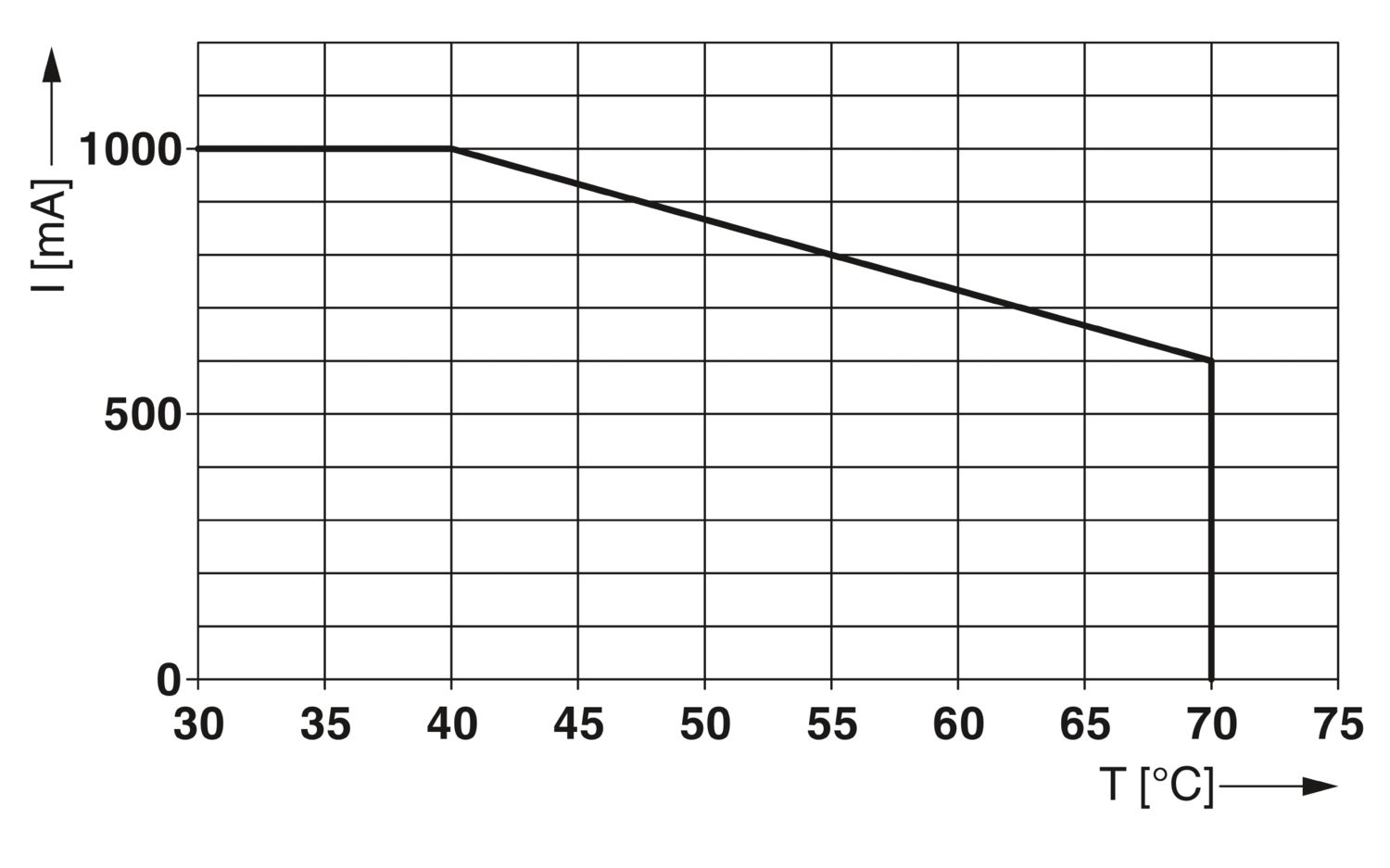
| Rated current | 1000 mA (40 °C) |
| Operating effective current IC at UC | ≤ 1 mA (in the signal circuit) |
| Protective conductor current IPE | ≤ 1 µA |
| Nominal discharge current In (8/20) µs (line-line) | 10 kA |
| Nominal discharge current In (8/20) µs (line-ground) | 10 kA |
| Pulse discharge current Iimp (10/350) µs (line-earth) | 2.5 kA |
| Total discharge current ITotal (8/20) µs | 20 kA |
| Voltage protection level Up (line-line) | ≤ 80 V (C1 - 1 kV / 500 A) |
| ≤ 130 V (C2 - 10 kV / 5 kA) | |
| ≤ 150 V (C2 - 10 kA) | |
| ≤ 55 V (C3 - 25 A) | |
| ≤ 60 V (C3 - 100 A) | |
| Voltage protection level Up (line-earth) | ≤ 900 V (C1 - 1 kV / 500 A) |
| ≤ 1300 V (C2 - 10 kV / 5 kA) | |
| ≤ 1200 V (C2 - 10 kA) | |
| ≤ 1000 V (C3 - 25 A) | |
| ≤ 1300 V (C3 - 100 A) | |
| Voltage protection level Up static (line-line) | ≤ 65 V (C1 - 1 kV / 500 A) |
| ≤ 65 V (C2 - 10 kA) | |
| Response time tA (line-line) | ≤ 1 ns |
| Response time tA (line-earth) | ≤ 100 ns |
| Input attenuation aE, sym. | typ. 0.3 dB (≤ 270 kHz/150 Ω) |
| Cut-off frequency fg (3 dB), sym. in 150 Ω system | typ. 1.1 MHz |
| Capacity (Core-Earth) | typ. 2 nF |
| Resistance per path | 1.2 Ω ±5 % |
| Surge protection fault message | Optical, multi-stage |
| Max. required back-up fuse | 1 A (FF) |
| Impulse durability (line-line) | C1 - 1 kV / 500 A |
| C2 - 10 kV / 5 kA | |
| C2 - 10 kA | |
| C3 - 100 A | |
| Impulse durability (line-earth) | C1 - 1 kV / 500 A |
| C2 - 10 kV / 5 kA | |
| C2 - 10 kA | |
| C3 - 100 A | |
| D1 - 2.5 kA | |
| Pulse reset time (line-line) | ≤ 4000 ms |
| Pulse reset time (line-earth) | ≤ 30 ms |
| Ambient conditions | |
| Degree of protection | IP20 |
| Ambient temperature (operation) | -40 °C ... 70 °C |
| Ambient temperature (storage/transport) | -40 °C ... 85 °C |
| Altitude | ≤ 4000 m (amsl) |
| Permissible humidity (operation) | 5 % ... 95 % |
| Standards/specifications | IEC 61643-21 |
| Note | 2000 + A1:2008, modified |
| Standards/specifications | EN 61643-21 |
| Note | 2001 + A1:2009 |
| Standards/specifications | EN 61000-6-3 |
| Note | 2007 + A1:2011 |
| Standards/specifications | EN 61000-6-2 |
| Note | 2005 |
| Mounting type | DIN rail: 35 mm |


Your advantages
Predictive monitoring with 3-stage LED display
Integration of the status message into the system controller via group remote signaling
Install quickly and error-free with DIN rail connectors
Maximum ease of maintenance, thanks to the 2-piece design
Maximum protection for MCR applications with high discharge capacity