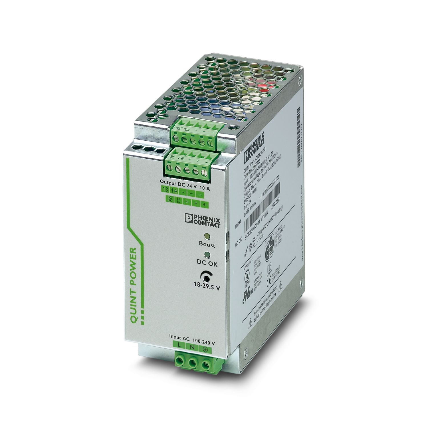
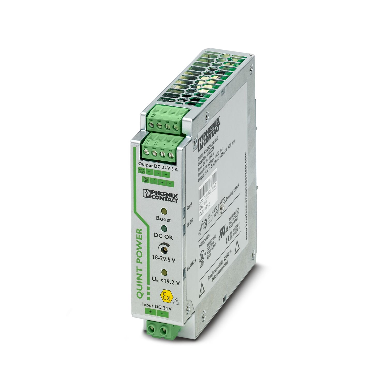
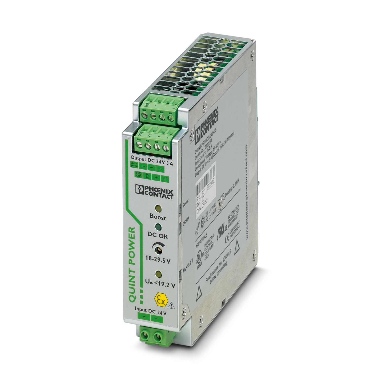
QUINT DC/DC converter with maximum functionality
DC/DC converters alter the voltage level, regenerate the voltage at the end of long cables or enable the creation of independent supply systems by means of electrical isolation.
QUINT DC/DC converters magnetically and therefore quickly trip circuit breakers with six times the nominal current, for selective and therefore cost-effective system protection. The high level of system availability is additionally ensured, thanks to preventive function monitoring, as it reports critical operating states before errors occur.
QUINT-PS/24DC/24DC/ 5/CO
-
DC/DC converter, protective coating
2320542
Primary-switched QUINT DC/DC converter for DIN rail mounting with SFB (Selective Fuse Breaking) Technology, with protective coating, input: 24 V DC, output: 24 V DC/5 A
Product details
| DC operation | |
| Nominal input voltage range | 24 V DC |
| Input voltage range | 18 V DC ... 32 V DC |
| Extended input voltage range in operation | 14 V DC ... 18 V DC (Derating) |
| Wide-range input | no |
| Input voltage range DC | 18 V DC ... 32 V DC |
| 14 V DC ... 18 V DC (Consider derating during operation) | |
| Voltage type of supply voltage | DC |
| Inrush current | typ. 15 A |
| Inrush current integral (I2t) | < 0.5 A2s |
| Mains buffering time | typ. 10 ms (24 V DC) |
| Current consumption | 7 A (24 V, IBOOST) |
| Reverse polarity protection | yes, ≤ 30 V DC |
| Protective circuit | Transient surge protection; Varistor |
| Input fuse | 15 A (Device protection) |
| Recommended breaker for input protection | 10 A ... 16 A (Characteristics B, C, D, K) |
| Efficiency | > 92 % |
| Output characteristic | U/I |
| Nominal output voltage | 24 V DC ±1 % |
| Setting range of the output voltage (USet) | 18 V DC ... 29.5 V DC (> 24 V DC, constant capacity restricted) |
| Nominal output current (IN) | 5 A (-25 °C ... 60 °C) |
| POWER BOOST (IBoost) | 6.25 A (-25 °C ... 40 °C permanent, UOUT = 24 V DC ) |
| Selective Fuse Breaking (ISFB) | 30 A (12 ms) |
| Magnetic circuit breaker tripping | B2 / B4 / C2 |
| Derating | 60 °C ... 70 °C (2.5 %/K) |
| Feedback voltage resistance | 35 V DC |
| Protection against overvoltage at the output (OVP) | < 35 V DC |
| Max. capacitive load | unlimited |
| Active current limitation | Approximately 7.2 A |
| Control deviation | < 1 % (change in load, static 10 % ... 90 %) |
| < 2 % (change in load, dynamic 10 % ... 90 %) | |
| < 0.1 % (change in input voltage ±10 %) | |
| Residual ripple | < 20 mVPP |
| Output power | 120 W |
| Peak switching voltages nominal load | < 10 mVPP (20 MHz) |
| Maximum no-load power dissipation | 2.4 W |
| Power loss nominal load max. | 11.4 W |
| Rise time | < 2 ms (UOUT (10 % ... 90 %)) |
| Connection in parallel | yes, for redundancy and increased capacity |
| Connection in series | yes |
| 2 (Devices) | |
| Signal: DC OK active | |
| Output description | UOUT > 0.9 x UN: High signal |
| Switching voltage range | 18 V DC ... 24 V DC |
| Maximum inrush current | < 20 mA (short-circuit-proof) |
| Signal: POWER BOOST, active | |
| Output description | IOUT < IN: High signal |
| Switching voltage range | 18 V DC ... 24 V DC |
| Maximum inrush current | < 20 mA (short-circuit-proof) |
| Signal: UIN OK, active | |
| Output description | UIN > 19.2 V: High signal |
| Switching voltage range | 18 V DC ... 24 V DC |
| Maximum inrush current | < 20 mA (short-circuit-proof) |
| Input | |
| Connection method | Screw connection |
| Conductor cross-section, rigid min. | 0.2 mm² |
| Conductor cross-section, rigid max. | 2.5 mm² |
| Conductor cross-section flexible min. | 0.2 mm² |
| Conductor cross-section flexible max. | 2.5 mm² |
| Conductor cross-section AWG min. | 24 |
| Conductor cross-section AWG max. | 12 |
| Stripping length | 8 mm |
| Screw thread | M3 |
| Tightening torque, min | 0.5 Nm |
| Tightening torque max | 0.6 Nm |
| Output | |
| Connection method | Screw connection |
| Conductor cross-section, rigid min. | 0.2 mm² |
| Conductor cross-section, rigid max. | 2.5 mm² |
| Conductor cross-section flexible min. | 0.2 mm² |
| Conductor cross-section flexible max. | 2.5 mm² |
| Conductor cross-section AWG min. | 24 |
| Conductor cross-section AWG max. | 12 |
| Stripping length | 7 mm |
| Screw thread | M3 |
| Tightening torque, min | 0.5 Nm |
| Tightening torque max | 0.6 Nm |
| Signal | |
| Conductor cross-section, rigid min. | 0.2 mm² |
| Conductor cross-section, rigid max. | 2.5 mm² |
| Conductor cross-section flexible min. | 0.2 mm² |
| Conductor cross-section flexible max. | 2.5 mm² |
| Conductor cross-section AWG min. | 24 |
| Conductor cross-section AWG max. | 12 |
| Screw thread | M3 |
| Tightening torque, min | 0.5 Nm |
| Tightening torque max | 0.6 Nm |
| Types of signaling | LED |
| Active switching output | |
| Relay contact | |
| Signal output: DC OK active | |
| Status display | "DC OK" LED green |
| Color | green |
| Signal output: POWER BOOST, active | |
| Status display | "BOOST" LED yellow/IOUT > IN : LED on |
| Color | yellow |
| Note on status display | LED on |
| Signal output: UIN OK, active | |
| Status display | LED "UIN < 19.2 V" yellow/UIN < 19.2 V DC: LED on |
| Color | yellow |
| Note on status display | LED on |
| Number of phases | 1 |
| Insulation voltage input/output | 1.5 kV (type test) |
| 1 kV (routine test) | |
| 1 kV (type test) |
| Product type | DC/DC converters |
| Product family | QUINT POWER |
| MTBF (IEC 61709, SN 29500) | > 890000 h (40 °C) |
| Insulation characteristics | |
| Protection class | III |
| Degree of pollution | 2 |
| Width | 32 mm |
| Height | 130 mm |
| Depth | 125 mm |
| Installation dimensions | |
| Installation distance right/left | 0 mm / 0 mm (≤ 70 °C) |
| Installation distance right/left (active) | 15 mm / 15 mm (≤ 70 °C) |
| Installation distance top/bottom | 50 mm / 50 mm (≤ 70 °C) |
| Installation distance top/bottom (active) | 50 mm / 50 mm (≤ 70 °C) |
| Alternative assembly | |
| Width | 122 mm |
| Height | 130 mm |
| Depth | 35 mm |
| Mounting type | DIN rail mounting |
| Assembly note | alignable: PN ≥50%, 5 mm horizontally, 15 mm next to active components, 50 mm vertically alignable: PN <50%, 0 mm horizontally, 40 mm vertically top, 20 mm vertically bottom |
| Mounting position | horizontal DIN rail NS 35, EN 60715 |
| With protective coating | yes |
| Housing material | Metal |
| Type of housing | Aluminum (AlMg3) |
| Hood version | Galvanized sheet steel, free from chrome (VI) |
| Ambient conditions | |
| Degree of protection | IP20 |
| Ambient temperature (operation) | -25 °C ... 70 °C (> 60 °C derating, 2.5 %/K, startup at -40°C type-tested) |
| Ambient temperature (storage/transport) | -40 °C ... 85 °C |
| Ambient temperature (start-up type tested) | -40 °C |
| Climatic class | 3K3 (in acc. with EN 60721) |
| Max. permissible relative humidity (operation) | 100 % (at 25 °C, non-condensing) |
| Shock | 18 ms, 30g, in each space direction (according to IEC 60068-2-27) |
| Vibration (operation) | < 15 Hz, amplitude ±2.5 mm (according to IEC 60068-2-6) |
| 15 Hz ... 150 Hz, 2.3g, 90 min. | |
| Temp code | T4 (-25 ... +70 °C; > 60 °C, Derating: 2,5 %/K) |
| Rail applications | EN 50121-4 |
| EN 50155 | |
| Standard – Electronic equipment for use in electrical power installations and their assembly into electrical power installations | EN 50178/VDE 0160 (PELV) |
| Standard - Electrical safety | EN 60950-1/VDE 0805 (SELV) |
| Standard – Safety extra-low voltage | EN 60950-1 (SELV) |
| EN 60204-1 (PELV) | |
| Standard - Safe isolation | DIN VDE 0100-410 |
| Shipbuilding approval | DNV GL (EMC B) |
| UL approvals | UL/C-UL listed UL 508 |
| UL/C-UL Recognized UL 60950-1 | |
| UL ANSI/ISA-12.12.01 Class I, Division 2, Groups A, B, C, D T4 (Hazardous Location) |
| Electromagnetic compatibility | Conformance with EMC Directive 2014/30/EU |
| EMC requirements for noise emission | EN 61000-6-3 |
| EN 61000-6-4 | |
| EMC requirements for noise immunity | EN 61000-6-1 |
| EN 61000-6-2 | |
| Electrostatic discharge | |
| Standards/regulations | EN 61000-4-2 |
| Electrostatic discharge | |
| Contact discharge | 8 kV (Test Level 4) |
| Discharge in air | 15 kV (Test Level 4) |
| Comments | Criterion A |
| Electromagnetic HF field | |
| Standards/regulations | EN 61000-4-3 |
| Electromagnetic HF field | |
| Frequency range | 80 MHz ... 1 GHz |
| Test field strength | 10 V/m |
| Frequency range | 1 GHz ... 2 GHz |
| Test field strength | 10 V/m |
| Frequency range | 2 GHz ... 3 GHz |
| Test field strength | 10 V/m |
| Comments | Criterion A |
| Fast transients (burst) | |
| Standards/regulations | EN 61000-4-4 |
| Fast transients (burst) | |
| Input | 2 kV (Test Level 3 - asymmetrical) |
| Output | 2 kV (Test Level 3 - asymmetrical) |
| Signal | 2 kV (Test Level 4 - asymmetrical) |
| Comments | Criterion A |
| Surge voltage load (surge) | |
| Standards/regulations | EN 61000-4-5 |
| Surge voltage load (surge) | |
| Input | 1 kV (Test Level 2 - symmetrical) |
| 2 kV (Test Level 3 - asymmetrical) | |
| Output | 1 kV (Test Level 2 - symmetrical) |
| 2 kV (Test Level 3 - asymmetrical) | |
| Signal | 1 kV (Test Level 2 - asymmetrical) |
| Comments | Criterion A |
| Conducted interference | |
| Standards/regulations | EN 61000-4-6 |
| Conducted interference | |
| Input/output/signal | asymmetrical |
| Frequency range | 0.15 MHz ... 80 MHz |
| Comments | Criterion A |
| Voltage | 10 V (Test Level 3) |
| Emitted interference | |
| Standards/regulations | EN 61000-6-3 |
| Radio interference voltage in acc. with EN 55011 | EN 55011 (EN 55022) Class B, area of application: Industry and residential |
| Emitted radio interference in acc. with EN 55011 | EN 55011 (EN 55022) Class B, area of application: Industry and residential |
| Criteria | |
| Criterion A | Normal operating behavior within the specified limits. |
| Criterion B | Temporary impairment to operational behavior that is corrected by the device itself. |
| Item number | 2320542 |
| Packing unit | 1 pc |
| Minimum order quantity | 1 pc |
| Sales key | ***** |
| Product key | CMDQ43 |
| GTIN | 4046356765930 |
| Weight per piece (including packing) | 845 g |
| Weight per piece (excluding packing) | 845 g |
| Customs tariff number | 85044030 |
| Country of origin | TH |
ETIM
| ETIM 8.0 | EC002540 |
UNSPSC
| UNSPSC 21.0 | 39121041 |
| EU RoHS | |
| Fulfills EU RoHS substance requirements | Yes |
| Exemption | 6(c), 7(a), 7(c)-I |
| China RoHS | |
| Environment friendly use period (EFUP) |
EFUP-25
An article-related China RoHS declaration table can be found in the download area for the respective article under "Manufacturer declaration". For all articles with EFUP-E, no China RoHS declaration table issued and required.
|
| EU REACH SVHC | |
| REACH candidate substance (CAS No.) | Lead (CAS: 7439-92-1) |
Compatible products
-
-
QUINT-PS/1AC/24DC/10/CO - Power supply, with protective coating 2320911
-
QUINT-PS/3AC/24DC/10 - Power supply 2866705
-
QUINT-ORING/24DC/2X10/1X20 - Redundancy module, with protective coating 2320173
-
UTA 107/30 - Mounting adapter 2320089
-
UWA 182/52 - Mounting adapter 2938235
-
QUINT-PS-ADAPTERS7/1 - Mounting adapter 2938196
-
CB TM1 1A SFB P - Thermal-magnetic device circuit breaker 2800836
-
CB TM1 2A SFB P - Thermal-magnetic device circuit breaker 2800837
-
CB TM1 12A SFB P - Thermal-magnetic device circuit breaker 2800844
-
CB TM1 16A SFB P - Thermal-magnetic device circuit breaker 2800845
Your advantages
Reliable starting of difficult loads, thanks to the static POWER BOOST power reserve with up to 125% nominal current permanently
Preventive function monitoring indicates critical operating states before errors occur
Constant voltage: output voltage regenerated even at the end of long cables
Support conversion to various voltage levels
Electrical isolation: for setting up independent supply systems
Optimum protection with dip coating for 100 % humidity
PHOENIX CONTACT (SEA) Pte Ltd
80 Bendemeer Road, #09-01A | #10-02 (Reception), Singapore 339949