Compact guide to explosion protection

Device selection in accordance with ATEX and IECEx

Explosive atmospheres can occur in almost all industrial applications. To safely prevent explosions, electrical devices in potentially explosive areas are subject to special requirements, directives, and standards. In this overview, you will find the criteria for appropriate device selection according to your application.

Download principles of explosion protection
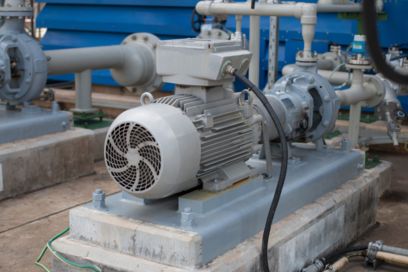
Chemical plant
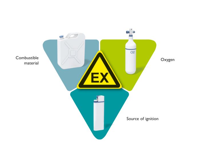
Representation of the components that create an explosion

Components that create an explosion: combustible materials, oxygen, ignition source

Principles of explosion protection

An explosion is an exothermic reaction with a sudden release of a large amount of energy, resulting in a strong blast wave.
An explosion occurs when a combustible material, oxygen, and an ignition source are present. If any one component is missing, no exothermic reaction occurs.

Various explosion protection measures exist to safely prevent explosions. While primary explosion protection prevents the presence of the explosive atmosphere, with secondary explosion protection an explosion is safely prevented by avoiding effective ignition sources by design. For example, effective ignition sources include electric sparks and hot surfaces of electrical equipment or electric arcs, static electricity, etc. Depending on the application, various types of protection with different protection principles exist for secondary explosion protection. There is also tertiary explosion protection. This involves design measures that reduce the consequences of an explosion to an acceptable level.

Selection of devices for secondary explosion protection

The following overview focuses on secondary explosion protection. When selecting devices, according to the types of protection, the user must analyze the type of danger and the duration and frequency of the danger. The type of danger is determined by examining the ignition source based on the ignition temperature and ignition energy. In the case of the duration and frequency of the danger, the relationship between zone classification and the equipment category and equipment protection level is established.

Temperature classes Ignition source: Hot surface

Devices for use in Group II (gases) potentially explosive atmospheres are divided into temperature classes (T1 - T6), which indicate the maximum device surface temperature that may occur. The surface temperature is valid for all parts of an item of electrical
equipment that can come into contact with the explosive gas mixture.
A device may only be used if the temperature assigned to the temperature class is lower than the ignition temperature of the gas mixture. Devices marked with a higher temperature class, i.e., lower surface temperature, may also be used with gas mixtures with a higher ignition temperature. A device with T6 marking may therefore be used for all gases.

For dusts, no distinction is made between temperature classes (T1 - T6). Devices for Group III (dusts) are marked with a maximum surface temperature. Additional dust deposits must be taken into account. You will find more information about temperature limits in the principles of explosion protection (see download).

Maximum surface temperature in °C

Ignition temperature range in °C

Examples

Temperature class
T1 450 >450 Carbon monoxide, methane, hydrogen
T2 300 >300 ... ≤450 Acetylene, butane, ethylene
T3 200 >200 ... ≤300 Gasoline, hydrogen sulfide, cyclohexane
T4 135 >135 ... ≤200 Acetaldehyde, diethyl ether (no other substances)
T5 100 >100 ... ≤135 No substances
T6 85 >85 ... ≤100 Carbon disulfide

Groups by ignition energies Ignition source: Sparks (energy)

Devices for use in Group II (gases) and III (dust) potentially explosive atmospheres are divided into groups (IIA - IIC, IIIA - IIIC), which indicate the maximum ignition energy of the device.
A device may only be used if the maximum ignition energy of the device is lower than the minimum ignition energy of the substance (gas or dust mixture). A device with IIC marking may be used for all gases and a device with IIIC marking may be used for all dusts.

Gases are more explosive than dusts, e.g., devices with IIB are suitable for IIIC.

Required ignition energy

Danger from substances

Examples of substances

Group
IIA +++ + Acetone, ethane, ammonia, carbon monoxide. Propane, butane, gasoline, diesel fuel, acetaldehyde
IIB ++ ++ Methane, ethylene, ethyl ether, ethyl alcohol, hydrogen sulfide
IIC + +++ Hydrogen, acetylene, carbon disulfide
IIIA +++ + Combustible flyings, e.g., cotton fibers
IIIB ++ ++ Non-conductive dust, e.g., flour, wood
IIIC + +++ Conductive dust, e.g., aluminum dust

Zone classification

Zone classification is the responsibility of the plant operator. It is regulated in Europe via the ATEX Directive 1999/92/EC (Workplace Directive). Furthermore, the operator must also comply with the requirements of IEC/EN 60079-10.

Zone classification (gases)

  • Zone 0:
    Area in which an explosive atmosphere consisting of a mixture of air and combustible materials in the form of gas, vapor, or mist is present continuously or for long periods or frequently
  • Zone 1:
    Area in which an explosive atmosphere consisting of a mixture of air and combustible materials in the form of gas, vapor, or mist is likely to occur in normal operation occasionally
  • Zone 2:
    Area in which an explosive atmosphere consisting of a mixture of air and combustible materials in the form of gas, vapor, or mist is not likely to occur in normal operation but, if it does occur, will persist for a short period only
Illustrative examples of zone classifications in a gas application
Zone 1
Area in which an explosive gas atmosphere is likely to occur in normal operation occasionally. This includes the immediate area surrounding zone 0, as well as areas close to filling and emptying equipment.
Zone 0
Area in which an explosive gas atmosphere is present continuously or for long periods. These conditions are usually present inside containers, pipelines, apparatus, and tanks.
Zone 2
Area in which an explosive gas atmosphere is not likely to occur in normal operation but, if it does occur, will persist for a short period only.

Zone classification (dusts)

  • Zone 20:
    Area in which an explosive atmosphere in the form of an airborne cloud of combustible dust is present continuously or for long periods or frequently
  • Zone 21:
    Area in which an explosive atmosphere in the form of an airborne cloud of combustible dust is likely to occur in normal operation occasionally
  • Zone 22:
    Area in which an explosive atmosphere in the form of an airborne cloud of combustible dust is not likely to occur in normal operation but, if it does occur, will persist for a short period only

Equipment categories or equipment protection levels

Equipment categories and equipment protection levels describe the safety level and the protection level of devices. Which devices are suitable for which zone is shown in ATEX Directive 2014/34/EU via the equipment category (categories 1, 2, 3). In standard IEC/EN 60079-0, the applicability of the devices for the respective zones is described via the equipment protection level (EPL: a, b, c). For both the equipment category marking and the equipment protection level, the G stands for “gas” and the D for “dust”. For example, in gas applications, a device marked 1G and Ga, i.e., with a very high level of safety and protection, is suitable for hazardous zone 0 and therefore also for all other gas zones. Structurally, this device is designed to still be safe in the event of two independent faults.

Safety level or protection level

Equipment category

ATEX Directive 2014/34/EU

Equipment protection level (EPL)

Standard IEC/EN 60079-0

Zone classification
Directive 1999/92/EC
Gas zones
Zone 0 Very high – the device is still safe in the event of two independent faults 1G Ga
Zone 1 High – the device is still safe in the event of a single independent fault 2G Gb
Zone 2 Normal – not failsafe 3G Gc
Dust zones
Zone 20 Very high – the device is still safe in the event of two independent faults 1D Da
Zone 21 High – the device is still safe in the event of a single independent fault 2D Db
Zone 22 Normal – not failsafe 3D Dc

Marking of Ex products

In Europe, in addition to the marking in accordance with standard IEC/EN 60079-0, there must also be a marking in accordance with ATEX Directive 2014/34/EU.

The ATEX Directive requires that equipment be classified into groups and categories. Equipment group I includes mining equipment liable to be endangered by firedamp and/or dust. Equipment group II includes all other Ex areas not related to mining, such as the chemical industry, oil and gas processing, potentially explosive dusts in mills and silos, etc.

The marking for the IEC/EN 60079 series of standards includes information about the type of protection, the gas and dust groups, the temperature class, and the equipment protection level (EPL).

Marking of intrinsically safety equipment for use in gas atmospheres
Marking of intrinsically safety equipment for use in dust atmospheres
Marking of associated equipment for use in gas atmospheres
Example marking of associated equipment for use in dust atmospheres
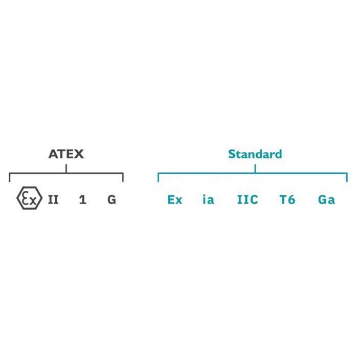
Marking of intrinsically safety equipment for use in gas atmospheres

ATEX

II – equipment group: I = mining | II = all non-mining Ex areas
1 – equipment category: 1 = suitable for zone 0/zone 20
G – atmosphere: G = gas

IEC/EN

i – type of protection: i = intrinsic safety
a – protection level: a = suitable for zone 0/zone 20
II – groups: II = gas
C – subgroups: C = hydrogen, acetylene, carbon disulfide
T6 – temperature class: T6 = 85°C
Ga – equipment protection level: G = gas | a = suitable for zone 0

Marking of intrinsically safety equipment for use in dust atmospheres

ATEX

II – equipment group: I = mining | II = all non-mining Ex areas
1 – equipment category: 1 = suitable for zone 0/zone 20
D – atmosphere: D = dust

IEC/EN

i – type of protection: i = intrinsic safety
a – protection level: a = suitable for zone 0/zone 20
III – groups: III = dust
C – subgroups: C = conductive dust, e.g., aluminum dust
125°C – max. surface temperature: 125°C = max. surface temperature of 125°C
Da – equipment protection level: D = dust, a = suitable for zone 20

Marking of associated equipment for use in gas atmospheres

ATEX

II – equipment group: I = mining | II = all non-mining Ex areas
1 – equipment category: 1 = suitable for zone 0/zone 20
( ) – brackets: Associated equipment (e.g., an intrinsically safe signal conditioner – located in the safe area, but the Ex i circuit is routed into the Ex area)
G – atmosphere: G = gas

IEC/EN

i – type of protection: i = intrinsic safety
a – protection level: a = suitable for zone 0/zone 20
Ga – equipment protection level: G = gas, a = suitable for zone 0
[ ] – brackets: Associated equipment (e.g., an intrinsically safe signal conditioner – located in the safe area, but the Ex i circuit is routed into the Ex area)
II – groups: II = gas
C – subgroups: C = hydrogen, acetylene, carbon disulfide

Example marking of associated equipment for use in dust atmospheres

ATEX

II – equipment group: I = mining | II = all non-mining Ex areas
1 – equipment category: 1 = suitable for zone 0/zone 20
( ) – brackets: Associated equipment (e.g., an intrinsically safe signal conditioner – located in the safe area, but the Ex i circuit is routed into the Ex area)
D – atmosphere: D = dust

IEC/EN

i – type of protection: i = intrinsic safety
a – protection level: a = suitable for zone 0/zone 20
Da – equipment protection level: D = dust, a = suitable for zone 20
[ ] – brackets: Associated equipment (e.g., an intrinsically safe signal conditioner – located in the safe area, but the Ex i circuit is routed into the Ex area)
III – groups: III = dust
C – subgroups: C = conductive dust, e.g., aluminum dust

Types of protection (excerpt) The following illustration explains some of the types of protection.

Graphical representation of Ex d – flameproof enclosure
Graphical representation of Ex e – increased safety
Graphical representation of Ex p – pressurized enclosure
Graphical representation of Ex m, Ex o, Ex q – molded encapsulation, sand filling, or oil immersion
Graphical representation of Ex i – intrinsic safety
Graphical representation of Ex n – type of protection “n”
Graphical representation of Ex d – flameproof enclosure

Principle:
Ignition source possible, explosion safely controlled

Protection concept:
Solid housing construction, type tests

Area of application:
Motors, switching devices, power electronics

Graphical representation of Ex e – increased safety

Principle:
Safe exclusion of ignition sources

Protection concept:
No operational ignition sources, exclusion of malfunction by special measures

Area of application:
Motors, transformers, luminaires, terminal blocks, busbar boxes

Graphical representation of Ex p – pressurized enclosure

Principle:
Safe exclusion of an explosive atmosphere

Protection concept:
Keep housing below overpressure with ignition protection gas

Area of application:
Machines, motors, control cabinets (electronics)

Graphical representation of Ex m, Ex o, Ex q – molded encapsulation, sand filling, or oil immersion

Principle:
Ignition source present, but safely controlled

Protection concept:
Embedding the equipment in molding compound, mineral oil, or sand

Area of application:
Electronics, transformers, capacitors, relays

Graphical representation of Ex i – intrinsic safety

Principle:
Sparks or thermal effects possible, but not ignitable

Protection concept:
Safe energy limitation taking into account faults and energy storage effects

Area of application:
Measurement and control technology, sensors, actuators, instrumentation

Graphical representation of Ex n – type of protection “n”

Simplification of all types of protection for the reduced requirements of zone 2/zone 22. No EU type test certificate is required. The following types of protection are available:

  • nA: non-sparking equipment (has been transferred to 60079-7 as Ex ec, but is still valid)
  • nC: sparking equipment or equipment with protected contacts
  • nR: restricted breathing housing
  • nL: energy-limited equipment (transferred to 60079-11 as Ex ic)
  • nZ: simplified pressurized enclosure (transferred to 60079-2 as Ex pzc)

Schematic representation of intrinsic safety from zone 0 to the safe zone

Ex i – intrinsic safety

Intrinsic safety (Ex i) type of protection has become established worldwide in the field of measurement and control technology in systems with potentially explosive areas. 
Intrinsically safe circuits are generally composed of the following elements:

  • The intrinsically safe equipment, i.e., a load installed in the Ex area (e.g., an Ex i temperature transmitter)
  • The associated equipment, i.e., a source installed in the non-Ex area (Ex i isolator)
  • The connecting line (cable).

The protection principle behind the Ex i type of protection is based on limiting the energy that is conducted to the potentially explosive area and is stored there. This means that the energy from any potential spark must always be less than the minimum ignition energy of the surrounding potentially explosive atmosphere.
To ensure that the respective connection cannot produce incendive sparks or hot surfaces, the user or system operator has to demonstrate and document “proof of intrinsic safety” in accordance with EN/IEC 60079-11 and construction standard EN/IEC 60079-14. This process offers the user the advantage of being able to select and combine Ex i field devices and Ex i isolators from different manufacturers in accordance with the specific requirements.

Application diagram of intrinsic safety from zone 0 through zone 1 and zone 2 to the safe zone

As opposed to all the other types of protection, Ex i refers not only to a single item of equipment but also to the entire intrinsically safe circuit, in accordance with IEC/EN 60079-11.

Advantages of “Ex i – intrinsic safety” type of protection:

  • Alterations during operation
  • Less expensive than other types of protection
  • Use of simple equipment
  • Use in zone 0/zone 20
Download
Principles of explosion protection
This document is intended for plant engineers and planners in potentially explosive areas. It covers international standards and directives. Operators of electrical equipment in potentially explosive areas will find information on which explosion protection criteria their plants must meet. There is also basic technical information on Group I and Group II, Ex zones, MCR technology, and functional safety.
View now
Cover image of the “Principles of explosion protection” document