
The PSR-UNI-L multifunctional safety relay is a flexible safety solution for industrial applications. It enables the monitoring of various items of safety equipment, e.g., emergency stop, safety doors, and light grids. Thanks to its configurability, it can be adapted to specific requirements.
PSR-UNI-L-1X4NO-1DO-24DC-PI
-
Safety relays
1487648
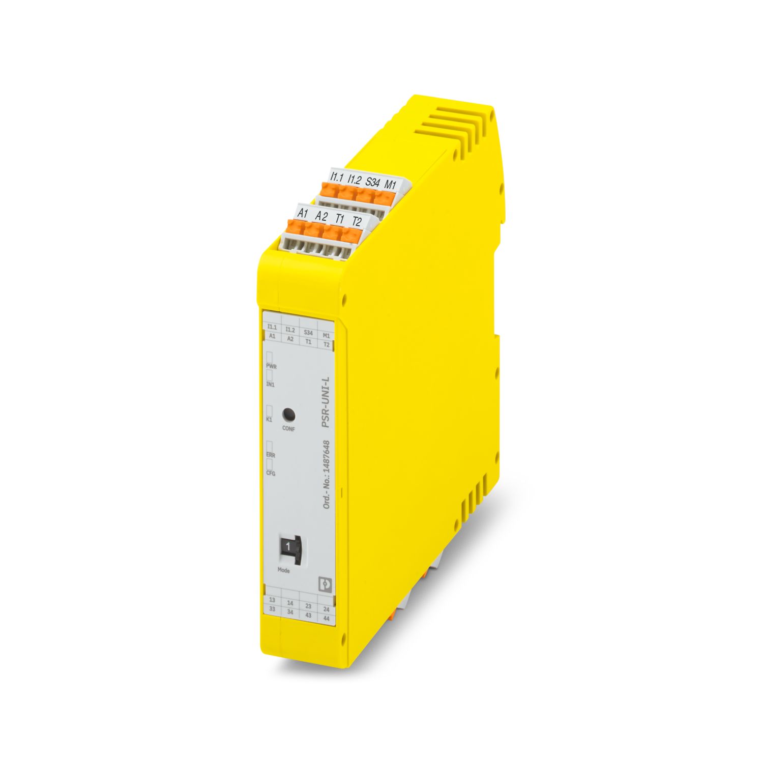
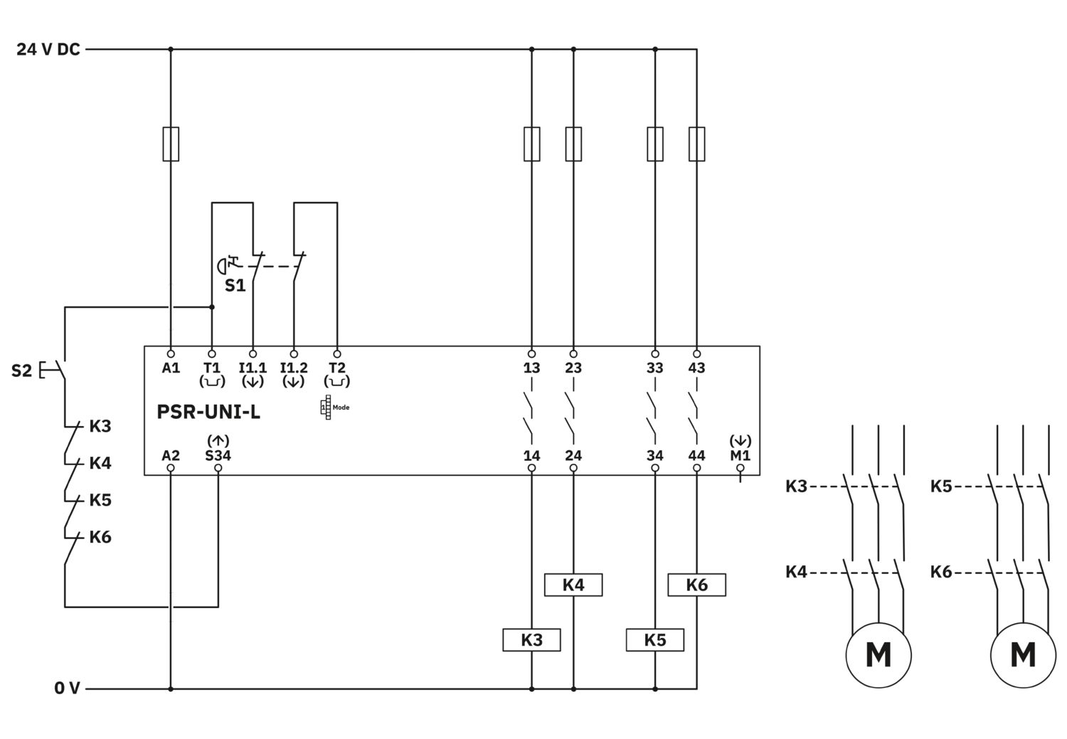
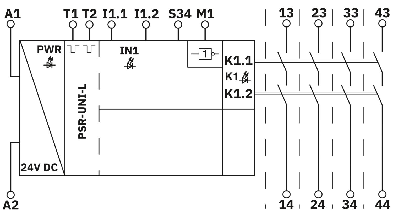
Configurable safety relay, multi functions, up to SIL 3, Cat. 4, PL e, 1 sensor circuit, 1-/2-channel operation, automatic/manual, monitored start, 1 x 4 enabling current paths, 1 signal output, US = 24 V DC, plug-in Push-in terminal block
Free download available.
Downloads
Product details
| Product family | PSRuni |
| Application | Emergency stop |
| Safety door | |
| Light grid | |
| Magnetic switch | |
| Two-hand control | |
| Safety shut-off mats | |
| Control | 1 and 2 channel |
| Relay type | Electromechanical relay with force-guided contacts in accordance with IEC/EN 61810-3 |
| Insulation characteristics | |
| Overvoltage category | III (Between logic and enabling current paths) |
| Degree of pollution | 2 |
| Times | |
| Typical response time | < 100 ms (Automatic/manual start) |
| < 500 ms (Safety shut-off mat operation) | |
| Typ. starting time with Us | 1 s (when controlled via A1; applicative control via A1/A2 is not permitted) |
| Typical release time | < 25 ms (on demand via the sensor circuit) |
| < 85 ms (Safety shut-off mat operation) | |
| < 25 ms (When requested via A1; applicative deactivation via A1/A2 is not permitted) | |
| Restart time | < 1 s (Boot time) |
| Recovery time | 500 ms (following demand of the safety function) |
| > 100 ms (Availability time after activating the sensor circuit during manual start) | |
| > 500 ms (Availability time after activating the sensor circuits during manual start in safety shut-off mat operation) | |
| Start pulse length | min. 500 ms (manual start) |
| Maximum power dissipation for nominal condition | 21.65 W (At US = 30 V, IL² = 100 A²) |
| Nominal operating mode | 100% operating factor |
| Rated insulation voltage | 250 V |
| Rated surge voltage/insulation | See data sheet, section “Insulation coordination”. |
| Supply | |
| Designation | A1/A2 |
| Rated control circuit supply voltage US | 24 V DC -20 % / +25 % |
| Rated control supply current IS | typ. 55 mA (When sensor circuit and start circuit are controlled internally) |
| typ. 45 mA (When sensor circuit and start circuit are controlled externally) | |
| Power consumption at US | typ. 1.32 W |
| Inrush current | typ. 35 A (Δt = 25 µs at Us) |
| Filter time | 1 ms (logic) |
| Protective circuit | Serial protection against polarity reversal |
| Suppressor diode | |
| Digital: Logic (I1.1, I1.2) | |
| Description of the input | safety-related |
| IEC 61131-2 type 3 | |
| Number of inputs | 2 |
| Input voltage range "0" signal | 0 V DC ... 5 V DC |
| Input voltage range "1" signal | 11 V DC ... 30 V DC |
| Input current range "0" signal | 0 mA ... 1.5 mA |
| Inrush current | < 45 mA (typ. with US, Δt <50 µs) |
| Filter time | max. 3 ms (Test pulse width of low test pulses) |
| min. 50 ms (Test pulse rate for low test pulse) | |
| < 1 ms (High test pulses at >100 ms test pulse rate possible) | |
| Concurrence | ∞ (2-channel wiring), 5 s (non-equivalent wiring), 0.5 s (two-hand control) |
| Limit frequency | min. 0 Hz |
| max. 0.1 Hz | |
| Max. permissible overall conductor resistance | 150 Ω |
| Protective circuit | Varistor |
| Current consumption | < 3.5 mA (typ. with US) |
| Digital: Start circuit (S34) | |
| Description of the input | non-safety-related |
| IEC 61131-2 type 3 | |
| Number of inputs | 1 |
| Input voltage range "0" signal | 0 V DC ... 5 V DC |
| Input voltage range "1" signal | 11 V DC ... 30 V DC |
| Input current range "0" signal | 0 mA ... 1.5 mA |
| Inrush current | < 45 mA (typ. with US) |
| Filter time | max. 3 ms (Test pulse width of low test pulses) |
| min. 50 ms (Test pulse rate for low test pulse) | |
| Limit frequency | min. 0 Hz |
| max. 0.1 Hz | |
| Max. permissible overall conductor resistance | 150 Ω |
| Protective circuit | Varistor |
| Current consumption | < 3.5 mA (typ. with US) |
| Relay: Enabling current paths (13/14, 23/24, 33/34, 43/44) | |
| Output description | safety-related |
| 2 NO contacts each in series, without delay, floating | |
| Number of outputs | 4 |
| Contact switching type | 4 enabling current paths |
| Contact material | AgSnO2 |
| Switching voltage | min. 10 V |
| max. 250 V AC/DC | |
| Switching power | min. 100 mW |
| Inrush current | min. 10 mA |
| max. 6 A | |
| Switching capacity | 5 A (AC15) |
| 5 A (DC13) | |
| Limiting continuous current | 6 A |
| Sq. Total current | 100 A2 (observe derating) |
| Switching frequency | max. 0.1 Hz |
| Mechanical service life | 10x 106 cycles |
| Output fuse | 6 A gL/gG |
| 4 A gL/gG (for low-demand applications) | |
| Signal: M1 | |
| Output description | non-safety-related |
| Number of outputs | 1 |
| Voltage | typ. (US - 2,5 V) |
| Current | max. 100 mA |
| Maximum inrush current | 500 mA (Δt = 10 ms at Us) |
| Ohmic load | min. 192 Ω (max.100 mA) |
| Switching frequency | max. 0.1 Hz |
| Protective circuit | Reverse polarity protection |
| Suppressor diode | |
| Short-circuit protection | Yes |
| Discharging circuit | no |
| Clock: T1, T2 | |
| Output description | non-safety-related |
| Number of outputs | 2 |
| Voltage | typ. (US - 2,5 V) |
| Current | max. 100 mA |
| Maximum inrush current | 500 mA (Δt = 10 ms at Us) |
| Protective circuit | Reverse polarity protection |
| Suppressor diode | |
| Short-circuit protection | Yes |
| Cable length | See inputs |
| Discharging circuit | no |
| Connection technology | |
| pluggable | yes |
| Conductor connection | |
| Connection method | Push-in connection |
| Conductor cross-section rigid | 0.2 mm² ... 2.5 mm² |
| Conductor cross-section flexible | 0.2 mm² ... 2.5 mm² |
| Conductor cross-section AWG | 24 ... 14 |
| Stripping length | 10 mm |
| Status display | 4 x LED (green, yellow, red) |
| Operating voltage display | 1 x LED (green, yellow, red) |
| Error indication | 1 x LED (red) |
| Width | 22.5 mm |
| Height | 107.9 mm |
| Depth | 111.7 mm |
| Color | yellow (RAL 1018) |
| Housing material | PA |
| Safety data | |
| Stop category | 0 |
| Safety data: EN ISO 13849 | |
| Performance level (PL) | e |
| Safety data: IEC 61508 - High demand | |
| Safety Integrity Level (SIL) | 3 |
| Safety data: IEC 61508 - Low demand | |
| Safety Integrity Level (SIL) | 3 |
| Safety data: EN IEC 62061 | |
| Safety Integrity Level (SIL) | 3 |
| Ambient conditions | |
| Degree of protection | IP20 |
| Min. degree of protection of inst. location | IP54 |
| Ambient temperature (operation) | -25 °C ... 60 °C (observe derating) |
| Ambient temperature (storage/transport) | -40 °C ... 85 °C |
| Maximum altitude | ≤ 2000 m (Above sea level) |
| Max. permissible humidity (storage/transport) | 75 % (on average, 85% infrequently, non-condensing) |
| Max. permissible relative humidity (operation) | 75 % (on average, 85% infrequently, non-condensing) |
| Shock | 15g |
| Vibration (operation) | 10 Hz ... 150 Hz, 2g |
| Mounting type | DIN rail mounting |
| Assembly note | See derating curve |
| Mounting position | vertical or horizontal |
| Item number | 1487648 |
| Packing unit | 1 pc |
| Minimum order quantity | 1 pc |
| Sales key | 02 |
| Product key | DNA191 |
| GTIN | 4063151930998 |
| Weight per piece (including packing) | 187.16 g |
| Weight per piece (excluding packing) | 164.66 g |
| Customs tariff number | 85371098 |
| Country of origin | DE |
ECLASS
| ECLASS-13.0 | 27371819 |
| ECLASS-15.0 | 27371819 |
| ECLASS-15.0 ASSET | 27250101 |
ETIM
| ETIM 9.0 | EC001449 |
UNSPSC
| UNSPSC 21.0 | 39122200 |
| EU RoHS | |
| Fulfills EU RoHS substance requirements | Yes |
| Exemption | 7(a), 7(c)-I |
| China RoHS | |
| Environment friendly use period (EFUP) |
EFUP-50
An article-related China RoHS declaration table can be found in the download area for the respective article under "Manufacturer declaration". For all articles with EFUP-E, no China RoHS declaration table issued and required.
|
| EU REACH SVHC | |
| REACH candidate substance (CAS No.) | Lead (CAS: 7439-92-1) |
| 2,2',6,6'-tetrabromo-4,4'-isopropylidenediphenol (CAS: 79-94-7) | |
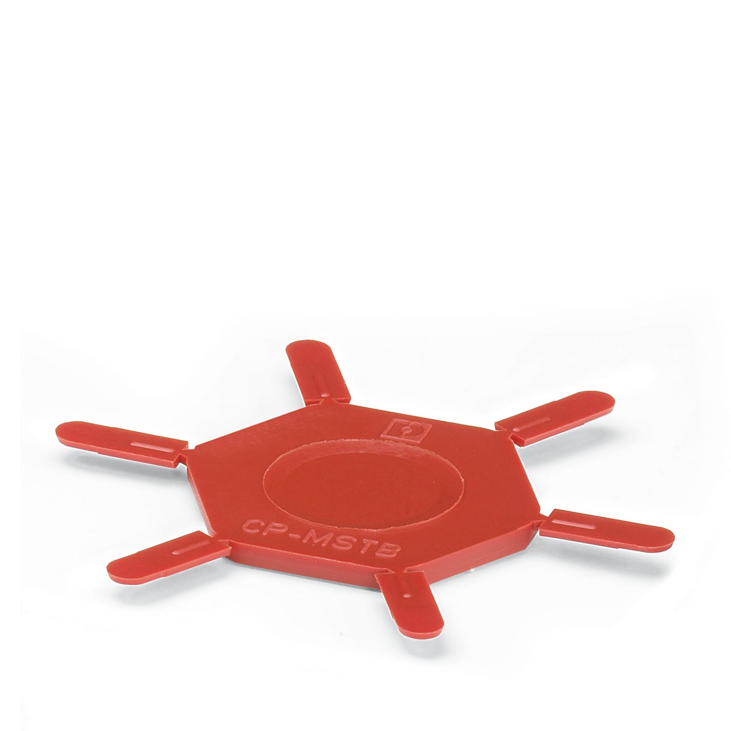
Compatible products
Your advantages
Up to Cat. 4/PL e in accordance with EN ISO 13849-1, SIL 3 in accordance with EN IEC 62061, SIL 3 in accordance with IEC 61508
Locally configurable
Configuration help via clipx ENGINEER device parameterization
1- and 2-channel control
Manually monitored and automatic activation in a single device
Low housing width of only 22.5mm
PHOENIX CONTACT S.A de C.V.
Lago Alberto No. 319 - Piso 9, Colonia Granada, Alcaldía Miguel Hidalgo, México, Ciudad de México, C.P. 11520