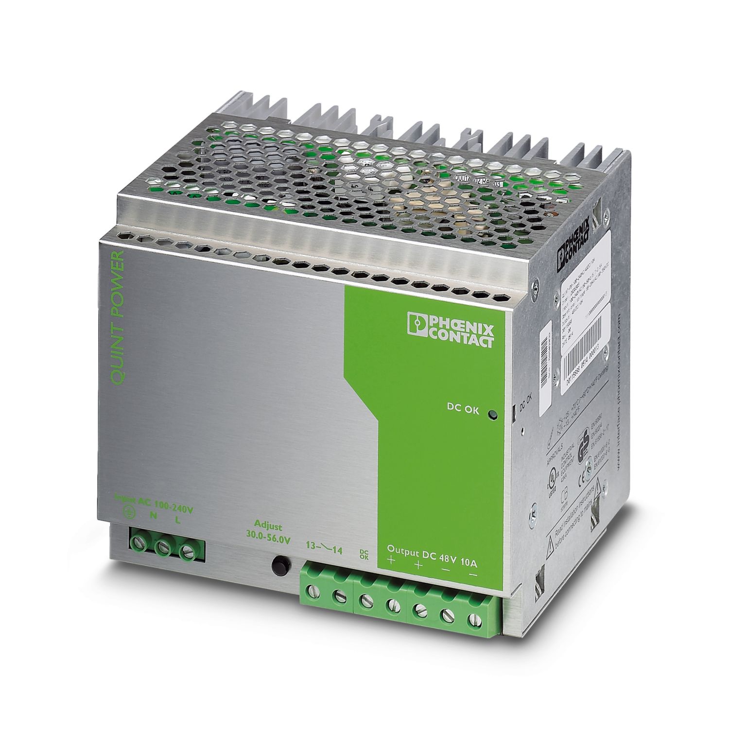
QUINT POWER 48 DC is a universal power supply unit of 240 W ... 960 W. In case of a regulated and adjustable output voltage of 30 V DC ... 56 V DC, output currents of 5 A, 10 A and 20 A are available.
The devices are built as primary switched-mode controllers and have a high degree of efficiency, due to which the heat loss is limited to a minimum.
The high operational safety is guaranteed reliably in unstable global networks as well. QUINT POWER also functions in applications where static voltage dips, transient failures of the supply voltage unit or phase failure are to be expected.
Generously dimensioned capacitors guarantee a mains buffering of more than 20 ms under full load. All three-phase QUINT POWER provide full output power, even in the event of a long-term phase failure.
A reliable starting of complex loads is ensured by a power reserve of up to 50% – the POWER BOOST.
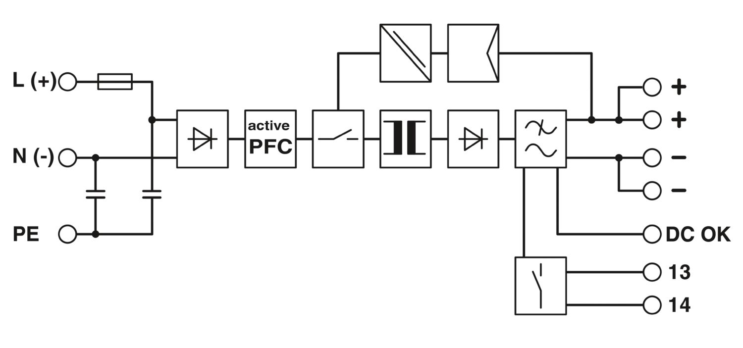
A preventive function monitoring diagnoses improper operating states and minimizes downtimes in your system. For remote monitoring of this state, an active transistor switching output and a floating relay contact are available.
QUINT-PS-100-240AC/48DC/10
-
Power supply
2938248
DIN rail power supply unit, primary-switched mode, 1-phase, output: 48 V DC / 10 A
Product details
AC operation | |
Nominal input voltage range | 100 V AC ... 240 V AC |
Input voltage range | 85 V AC ... 264 V AC |
90 V DC ... 350 V DC | |
Input voltage range AC | 85 V AC ... 264 V AC |
Input voltage range DC | 90 V DC ... 350 V DC |
Voltage type of supply voltage | AC/DC |
Inrush current | < 15 A (3.2 A2s) |
Inrush current integral (I2t) | 3.2 A2s |
AC frequency range | 45 Hz ... 65 Hz |
Frequency range DC | 0 Hz |
Mains buffering time | > 30 ms (120 V AC) |
> 35 ms (230 V AC) | |
Current consumption | approx. 4.76 A (120 V AC) |
2.3 A (230 V AC) | |
Nominal power consumption | 524 W |
Protective circuit | Transient surge protection; Varistor |
Typical response time | < 1 s |
Input fuse | 12 A (slow-blow, internal) |
Permissible backup fuse | B10 B16 |
Recommended breaker for input protection | 10 A ... 16 A (Characteristics B, C, D, K) |
Discharge current to PE | < 3.5 mA |
Efficiency | > 90 % |
Nominal output voltage | 48 V DC ±1 % |
Setting range of the output voltage (USet) | 30 V DC ... 56 V DC |
Nominal output current (IN) | 10 A (up to 60 °C) |
Output current limit | 13 A (approx. IBOOST, for short-circuit) |
POWER BOOST (IBoost) | 13 A |
Derating | 60 °C (2.5 %/K) |
Feedback voltage resistance | 60 V DC |
Protection against overvoltage at the output (OVP) | ≤ 60 V DC |
Max. capacitive load | unlimited |
Control deviation | < 1 % (change in load, static 10 % ... 90 %) |
< 5 % (change in load, dynamic 10 % ... 90 %) | |
< 0.1 % (change in input voltage ±10 %) | |
Residual ripple | < 20 mVPP (with nominal values) |
Output power | 480 W |
Peak switching voltages nominal load | < 50 mVPP |
Maximum no-load power dissipation | < 5 W |
Power loss nominal load max. | < 56 W |
Rise time | < 2 ms (UOUT (10 % ... 90 %)) |
Connection in parallel | yes, for redundancy and increased capacity |
Connection in series | yes |
Signal: DC OK active | |
Output description | UOUT > 0.9 x UN: High signal |
Maximum switching voltage | ≤ 24 V |
Output voltage | + 24 V DC |
Maximum inrush current | ≤ 40 mA |
Continuous load current | ≤ 40 mA |
Signal: DC OK floating | |
Output description | Relay contact, UOUT > 0.9 x UN: Contact closed |
Maximum switching voltage | ≤ 30 V AC/DC |
Maximum inrush current | ≤ 1 A |
Continuous load current | ≤ 1 A |
Input | |
Connection method | Screw connection |
Conductor cross-section, rigid min. | 0.2 mm² |
Conductor cross-section, rigid max. | 6 mm² |
Conductor cross-section flexible min. | 0.2 mm² |
Conductor cross-section flexible max. | 4 mm² |
Conductor cross-section AWG min. | 24 |
Conductor cross-section AWG max. | 10 |
Stripping length | 7 mm |
Screw thread | M3 |
Tightening torque, min | 0.5 Nm |
Tightening torque max | 0.6 Nm |
Output | |
Connection method | Screw connection |
Conductor cross-section, rigid min. | 0.5 mm² |
Conductor cross-section, rigid max. | 16 mm² |
Conductor cross-section flexible min. | 0.5 mm² |
Conductor cross-section flexible max. | 10 mm² |
Conductor cross-section AWG min. | 20 |
Conductor cross-section AWG max. | 6 |
Stripping length | 7 mm |
Screw thread | M4 |
Tightening torque, min | 1.2 Nm |
Tightening torque max | 1.5 Nm |
Signal | |
Conductor cross-section, rigid min. | 0.5 mm² |
Conductor cross-section, rigid max. | 16 mm² |
Conductor cross-section flexible min. | 0.5 mm² |
Conductor cross-section flexible max. | 10 mm² |
Conductor cross-section AWG min. | 20 |
Conductor cross-section AWG max. | 6 |
Screw thread | M4 |
Tightening torque, min | 1.2 Nm |
Tightening torque max | 1.5 Nm |
Types of signaling | LED |
Active switching output | |
Relay contact | |
Signal output: DC OK active | |
Status display | "DC OK" LED green |
Note on status display | UOUT < 0.9 x UN: LED flashing |
Signal output: DC OK floating | |
Status display | "DC OK" LED green |
Note on status display | UOUT < 0.9 x UN: LED flashing |
Number of phases | 1 |
Insulation voltage input/output | 4 kV AC (type test) |
2 kV AC (routine test) | |
Insulation voltage output / PE | 500 V DC (routine test) |
Insulation voltage input / PE | 3.5 kV AC (type test) |
2 kV AC (routine test) |
Product type | Power supply |
Product family | QUINT POWER |
MTBF (IEC 61709, SN 29500) | > 500000 h |
Insulation characteristics | |
Protection class | I (with PE connection) |
Degree of pollution | 2 |
Dimensional drawing |
|
Width | 157 mm |
Height | 130 mm |
Depth | 125 mm |
Alternative assembly | |
Width | 122 mm |
Height | 130 mm |
Depth | 160 mm |
Mounting type | DIN rail mounting |
Assembly note | alignable: horizontally 0 mm, vertically 50 mm |
Mounting position | horizontal DIN rail NS 35, EN 60715 |
Housing material | Metal |
Type of housing | AluNox (AlMg1) |
Ambient conditions | |
Degree of protection | IP20 |
Ambient temperature (operation) | -25 °C ... 70 °C (> 60 °C Derating: 2,5 %/K) |
Ambient temperature (storage/transport) | -40 °C ... 85 °C |
Climatic class | 3K3 (in acc. with EN 60721) |
Max. permissible relative humidity (operation) | 95 % (at 25 °C, non-condensing) |
Shock | 18 ms, 30g, in each space direction (according to IEC 60068-2-27) |
Vibration (operation) | < 15 Hz, amplitude ±2.5 mm (according to IEC 60068-2-6) |
15 Hz ... 150 Hz, 2.3g, 90 min. |
Standard – Electronic equipment for use in electrical power installations and their assembly into electrical power installations | EN 50178/VDE 0160 (PELV) |
Standard – Limitation of mains harmonic currents | EN 61000-3-2 |
Standard - Electrical safety | EN 60950-1/VDE 0805 (SELV) |
EN 61558-2-17 | |
Standard - Equipment safety | GS (tested safety) |
Standard – Protection against shock currents, basic requirements for protective separation in electrical equipment | EN 50178 |
Standard – Safety extra-low voltage | EN 60950-1 (SELV) |
EN 60204 (PELV) | |
Standard - Safe isolation | DIN VDE 0100-410 |
Standard - Safety of transformers | EN 61558-2-17 |
Overvoltage category | |
EN 62477-1 | III |
Shipbuilding approval | DNV GL (EMC A), ABS |
UL approvals | UL/C-UL listed UL 508 |
UL/C-UL Recognized UL 60950-1 |
Electromagnetic compatibility | Conformance with EMC Directive 2014/30/EU |
Low Voltage Directive | Conformance with Low Voltage Directive 2014/35/EC |
EMC requirements for noise emission | EN 61000-6-3 |
EN 61000-6-4 | |
EMC requirements for noise immunity | EN 61000-6-1 |
EN 61000-6-2 | |
Electrostatic discharge | |
Standards/regulations | EN 61000-4-2 |
Housing | Level 4 |
Electrostatic discharge | |
Contact discharge | 8 kV |
Discharge in air | 15 kV |
Comments | Criterion B |
Electromagnetic HF field | |
Standards/regulations | EN 61000-4-3 |
Electromagnetic HF field | |
Frequency range | 80 MHz ... 1 GHz |
Test field strength | 10 V/m |
Comments | Criterion A |
Fast transients (burst) | |
Standards/regulations | EN 61000-4-4 |
Fast transients (burst) | |
Input | 4 kV (level 4 - asymmetrical: conductor to ground) |
Output | 2 kV (level 3 - asymmetrical: conductor to ground) |
Signal | 1 kV (level 1 - asymmetrical: conductor to ground) |
Comments | Criterion B |
Surge voltage load (surge) | |
Standards/regulations | EN 61000-4-5 |
Surge voltage load (surge) | |
Input | 4 kV (inst. class 4 - asymmetrical: conductor to ground) |
2 kV (inst. class 4 -symmetrical: conductor to conductor) | |
Output | 0.5 kV (level 1 - asymmetrical: conductor to ground) |
0.5 kV (level 1 - symmetrical: conductor to conductor) | |
Signal | 1 kV (level 2 - asymmetrical: conductor to ground) |
Comments | Criterion B |
Conducted interference | |
Standards/regulations | EN 61000-4-6 |
Conducted interference | |
Input/output/signal | Level 3 - asymmetrical |
Frequency range | 0.15 MHz ... 80 MHz |
Comments | Criterion A |
Voltage | 10 V |
Voltage dips | |
Standards/regulations | EN 61000-4-11 |
Emitted interference | |
Standards/regulations | EN 61000-6-3 |
Radio interference voltage in acc. with EN 55011 | EN 55011 (EN 55022) Class B, area of application: Industry and residential |
Emitted radio interference in acc. with EN 55011 | EN 55011 (EN 55022) Class B, area of application: Industry and residential |
Item number | 2938248 |
Packing unit | 1 pc |
Minimum order quantity | 1 pc |
Sales key | 02 |
Product key | CMPP14 |
GTIN | 4046356013178 |
Weight per piece (including packing) | 3,033 g |
Weight per piece (excluding packing) | 2,500 g |
Customs tariff number | 85438910 |
Country of origin | TH |
EU RoHS | |
Fulfills EU RoHS substance requirements | Yes |
Exemption | 6(c), 7(a), 7(c)-I |
China RoHS | |
Environment friendly use period (EFUP) |
EFUP-25
An article-related China RoHS declaration table can be found in the download area for the respective article under "Manufacturer declaration". For all articles with EFUP-E, no China RoHS declaration table issued and required.
|
EU REACH SVHC | |
REACH candidate substance (CAS No.) | Lead (CAS: 7439-92-1) |
Compatible products
PHOENIX CONTACT S.A de C.V.
Lago Alberto No. 319 - Piso 9, Colonia Granada, Alcaldía Miguel Hidalgo, México, Ciudad de México, C.P. 11520