
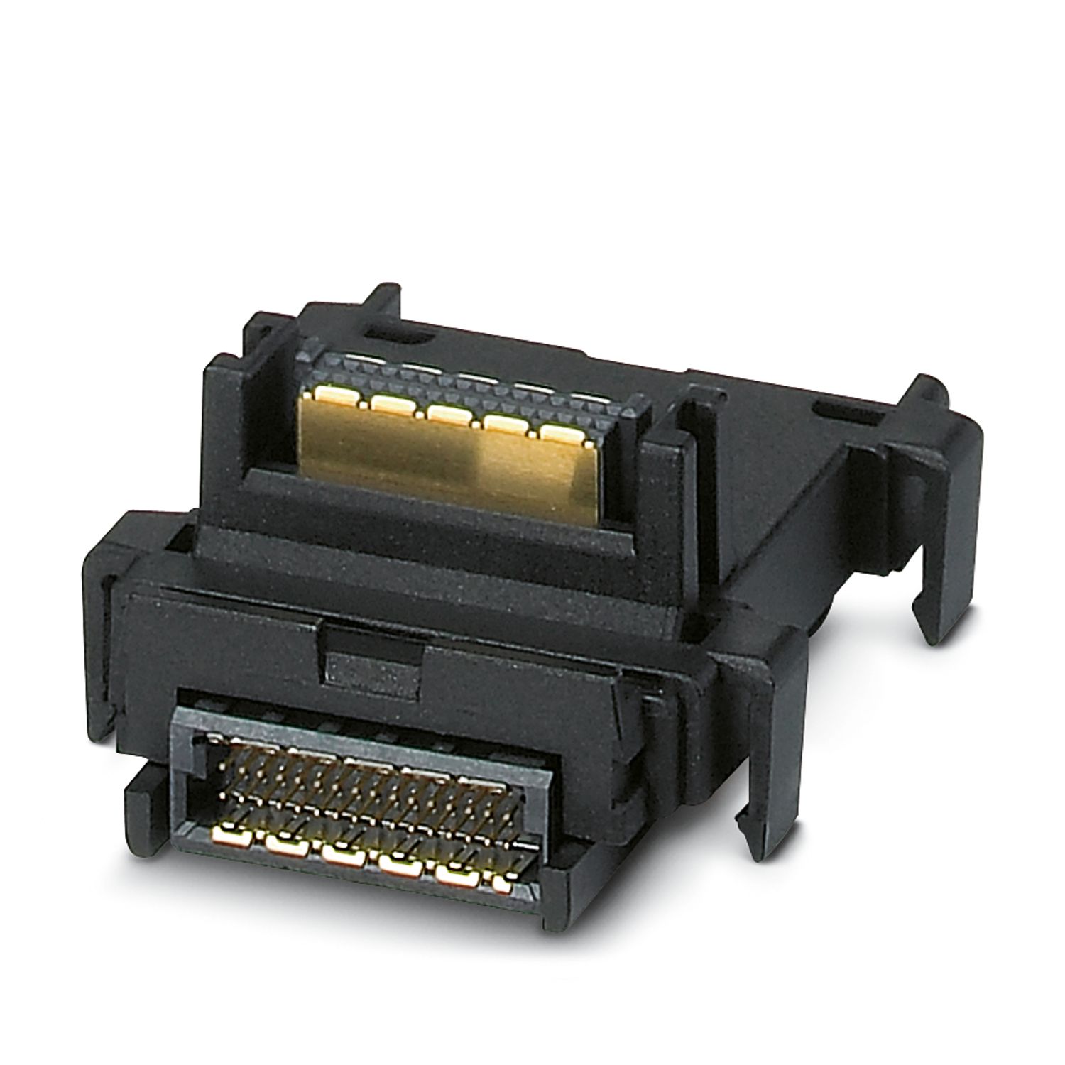
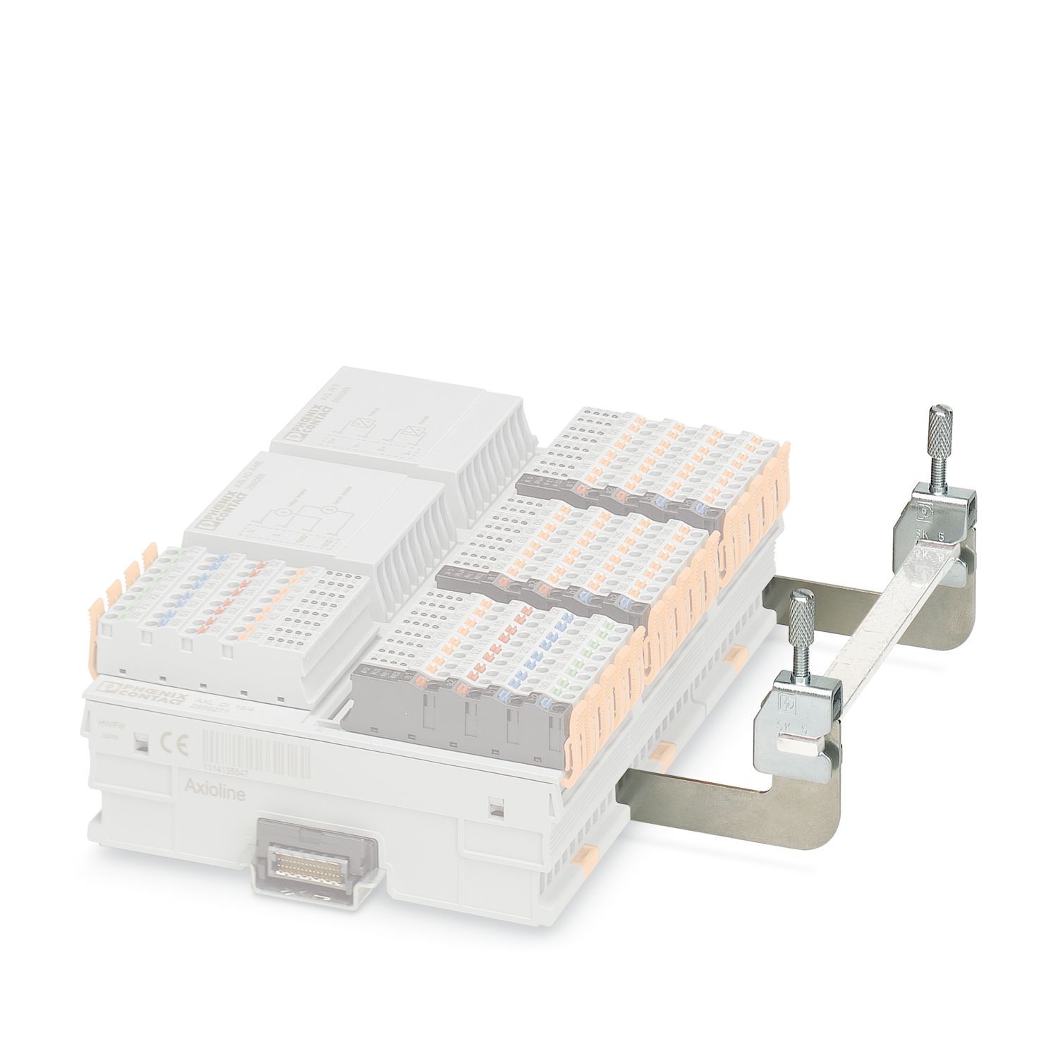
The module is designed for use within an Axioline F station. Used to evaluate strain gauges that may be located in weighing cells or load cells, for example. You can connect the strain gauges using 6- or 4-conductor technology.
AXL F SGI2 1H
-
Analog module
2702911
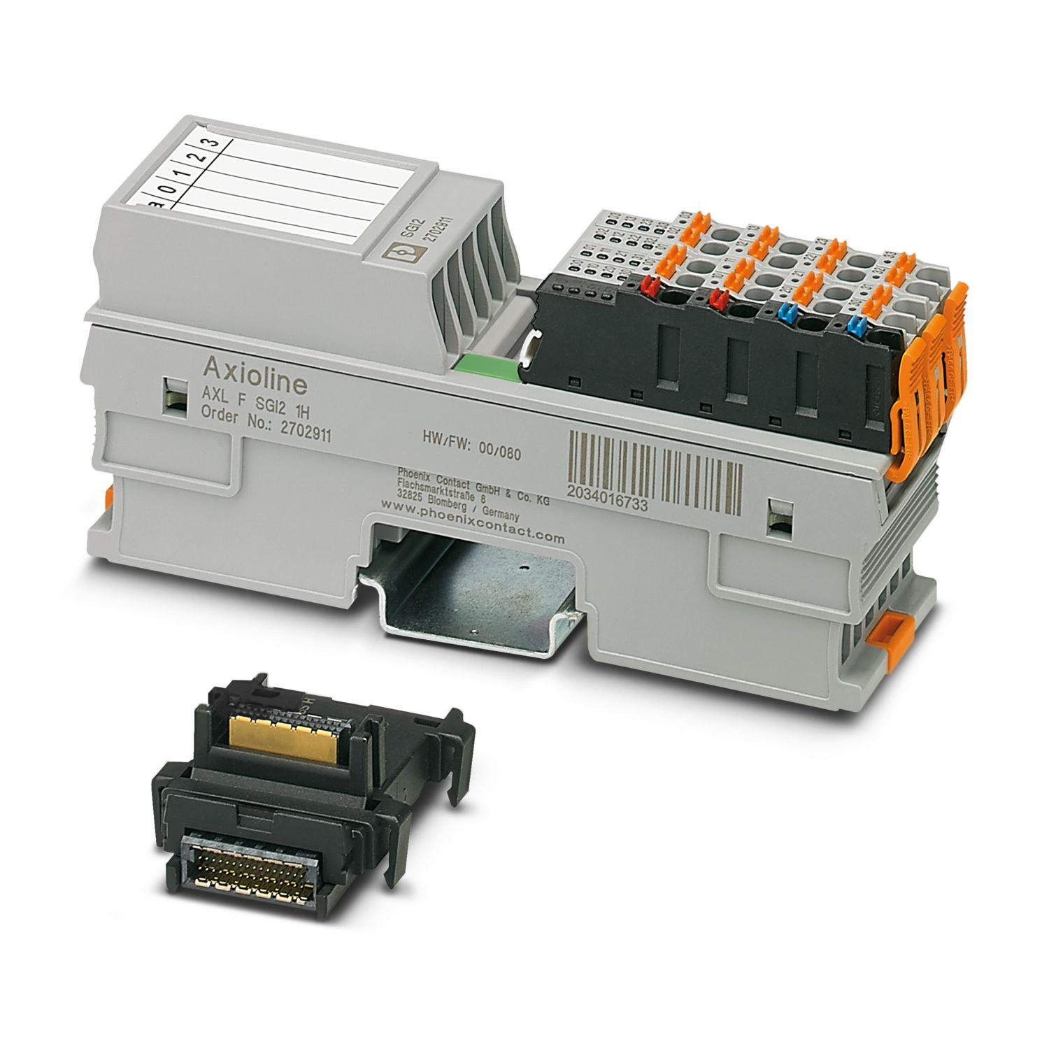


Axioline F, Strain gauge capture module, transmission speed in the local bus: 100 Mbps, degree of protection: IP20, including bus base module and Axioline F connectors
Free download available.
Downloads
Product details
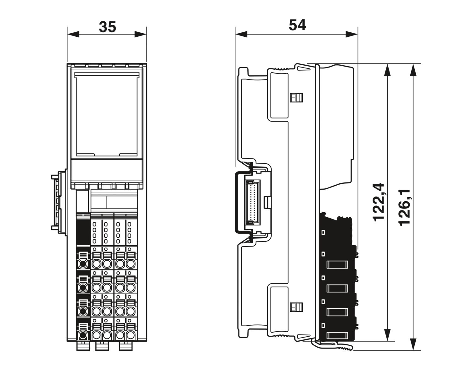
| Dimensional drawing |
|
| Width | 35 mm |
| Height | 126.1 mm |
| Depth | 54 mm |
| Note on dimensions | The depth applies when a TH 35-7.5 DIN rail is used (in accordance with EN 60715). |
| Note on application | |
| Note on application | Only for industrial use |
| Axioline F local bus | |
| Number of interfaces | 2 |
| Connection method | Bus base module |
| Transmission speed | 100 Mbps |
| Module | |
| ID code (hex) | none |
| Input address area | 12 Byte |
| Output address area | 12 Byte |
| Required parameter data | 48 Byte |
| Required configuration data | 7 Byte |
| Analog | |
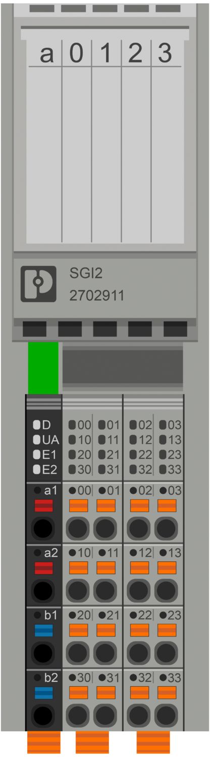
| Description of the input | Input channels for strain gauge |
| Number of inputs | 2 |
| Connection technology | 6 or 4-wire, twisted pair shielded cable |
| Bridge difference Ud | Measuring range specified by selecting the characteristic |
| -35 mV ... +35 mV | |
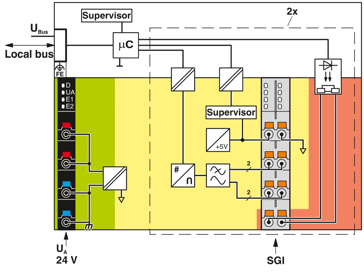
| Bridge voltage U0 | 5 V |
| Measured value representation | 32 bits |
| Characteristics | can be parameterized: 350 μV/V ... 6500 μV/V |
| Contacts | |
| Description | Floating N/O contact |
| Quantity | 2 (Ka1-Kb1, Ka2-Kb2) |
| Contact resistance | < 1 Ω (typical) |
| < 3 Ω (maximum) | |
| Typical response time | typ. 0.2 ms (opening) |
| typ. 2 ms (close) | |
| Analog | |
| Output description | Jumper supply |
| Number of outputs | 2 |
| Impedance | > 43 Ω (per channel) |
| Output voltage | typ. 5 V |
| Output current | max. 115 mA (per channel) |
| Product family | Axioline F |
| Type | block modular |
| Mounting position | any (no temperature derating) |
| Scope of supply | including bus base module and Axioline F connectors |
| Operating mode | Process data mode with 6 words |
| Maximum power dissipation for nominal condition | 1.85 W |
| Potentials: Axioline F local bus supply (UBus) | |
| Supply voltage | 5 V DC (via bus base module) |
| Current draw | max. 75 mA |
| typ. 65 mA | |
| Potentials: Supply for analog modules (UA) | |
| Supply voltage | 24 V DC |
| Supply voltage range | 19.2 V DC ... 30 V DC (including all tolerances, including ripple) |
| Current draw | typ. 110 mA (with maximum load: 8 weighing cells with 350 Ω per channel) |
| typ. 25 mA (with typical load: 1 weighing cell with 350 Ω, only one channel loaded) | |
| typ. 55 mA (with maximum load: 8 weighing cells with 350 Ω, only one channel loaded) | |
| Protective circuit | Surge protection; Suppressor diode |
| Reverse polarity protection; Polarity protection diode | |
| Electrical isolation/isolation of the voltage ranges | |
| Test voltage: Logic | 500 V AC, 50 Hz, 1 min |
| Test voltage: 24 V supply (I/O) | 500 V AC, 50 Hz, 1 min |
| Test voltage: Analog inputs | 500 V AC, 50 Hz, 1 min |
| Test voltage: N/O contact Ka1 - Kb1 | 500 V AC, 50 Hz, 1 min |
| Test voltage: N/O contact Ka2 - Kb2 | 500 V AC, 50 Hz, 1 min |
| Test voltage: Functional ground | 500 V AC, 50 Hz, 1 min |
| Connection technology | |
| Connection name | Axioline F connector |
| Note on the connection method | Please observe the information provided on conductor cross-sections in the “Axioline F: system and installation” user manual. |
| Applications with UL approval: only use copper conductors. | |
| Conductor connection | |
| Connection method | Push-in connection |
| Conductor cross-section rigid | 0.2 mm² ... 1.5 mm² |
| Conductor cross-section flexible | 0.2 mm² ... 1.5 mm² |
| Conductor cross-section AWG | 24 ... 16 |
| Stripping length | 8 mm |
| Axioline F connector | |
| Connection method | Push-in connection |
| Note on the connection method | Please observe the information provided on conductor cross-sections in the “Axioline F: system and installation” user manual. |
| Applications with UL approval: only use copper conductors. | |
| Conductor cross-section, rigid | 0.2 mm² ... 1.5 mm² |
| Conductor cross-section, flexible | 0.2 mm² ... 1.5 mm² |
| Conductor cross-section AWG | 24 ... 16 |
| Stripping length | 8 mm |
| Ambient conditions | |
| Ambient temperature (operation) | -25 °C ... 60 °C |
| Degree of protection | IP20 |
| Air pressure (operation) | 70 kPa ... 106 kPa (up to 3000 m above sea level) |
| Air pressure (storage/transport) | 70 kPa ... 106 kPa (up to 3000 m above sea level) |
| Ambient temperature (storage/transport) | -40 °C ... 85 °C |
| Permissible humidity (operation) | 5 % ... 95 % (non-condensing) |
| Permissible humidity (storage/transport) | 5 % ... 95 % (non-condensing) |
| Protection class | III (IEC 61140, EN 61140, VDE 0140-1) |
| Mounting type | DIN rail mounting |
| Mounting position | any (no temperature derating) |
Your advantages
2 high-precision inputs for strain gauges
Measuring ranges adjusted with nominal characteristic values upon delivery
Manual entry of characteristic values
Process data update can be parameterized in increments between 200 µs and 100 ms
Path adjustment in the process environment
2-point adjustment
Connection of strain gauges in 6- and 4-conductor technology
Advanced wire-break detection
Sensor supply of up to 115 mA (8 load cells with 350 Ω per channel)
Per channel: low-resistance, floating N/O contact
The channels are parameterized independently of one another via the bus system
Tara device