
The module is an Axioline F I/O module for use in the Axioline F modular I/O system. The module is a modular I/O device that can be affixed to the Axioline F local bus, to communicate I/O data up to the Axioline F controller or bus coupler, which forms the head of the station. The module allows the connection of up to four HART devices. The analog output I/O module with HART capabilities manages analog output and HART data to and from the field I/O terminals and makes this information available to the controller / bus coupler through the Axioline F local bus.
AXL F AO4 HART XC 1F
-
Analog module
1087080
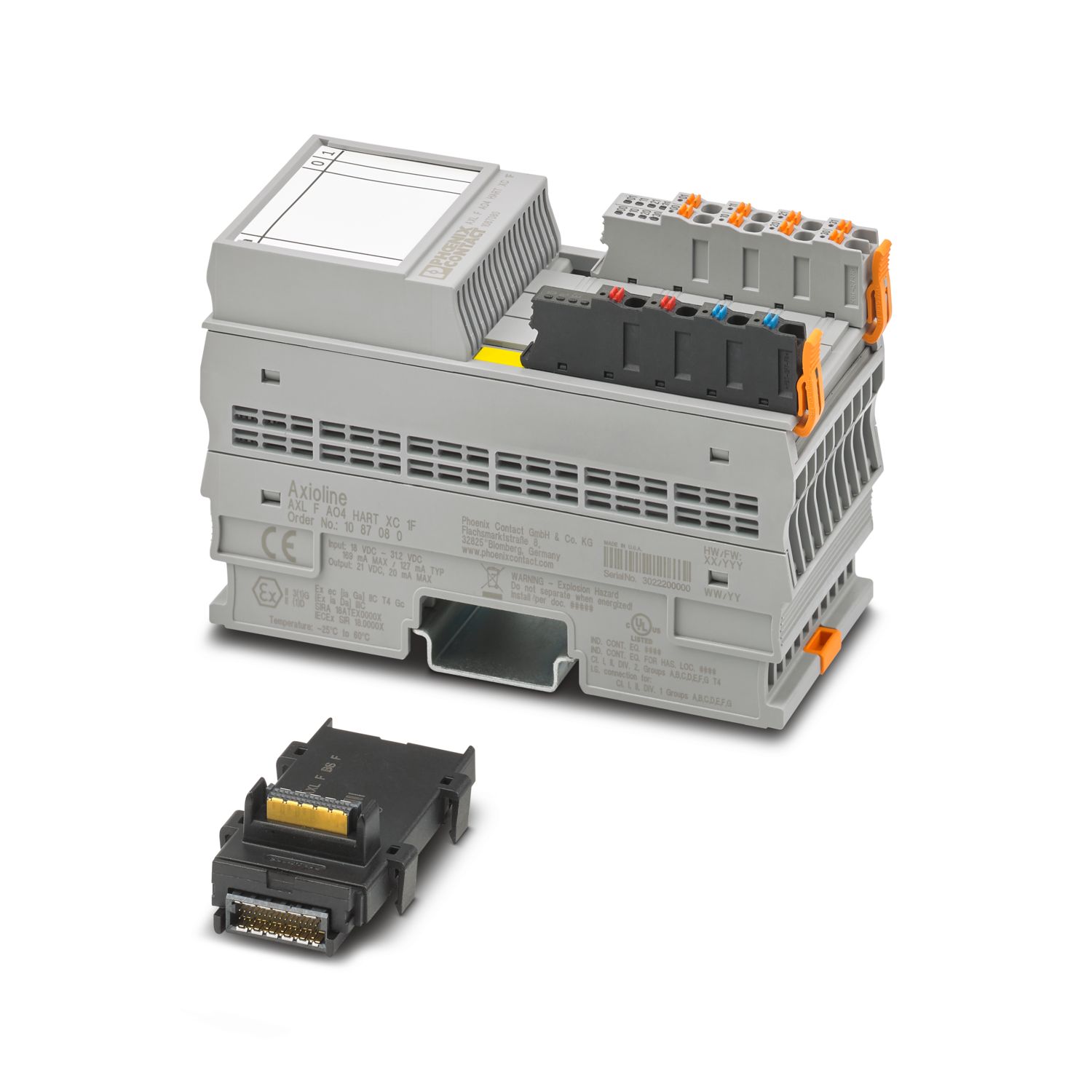
Axioline F, Analog output module, Analog outputs: 4 (HART), 0 mA ... 20 mA, 4 mA ... 20 mA, connection technology: 2-conductor, transmission speed in the local bus: 100 Mbps, Extreme conditions version, HART functionality, degree of protection: IP20, including bus base module and Axioline F connectors
Free download available.
Downloads
Product details
| Dimensional drawing |
|
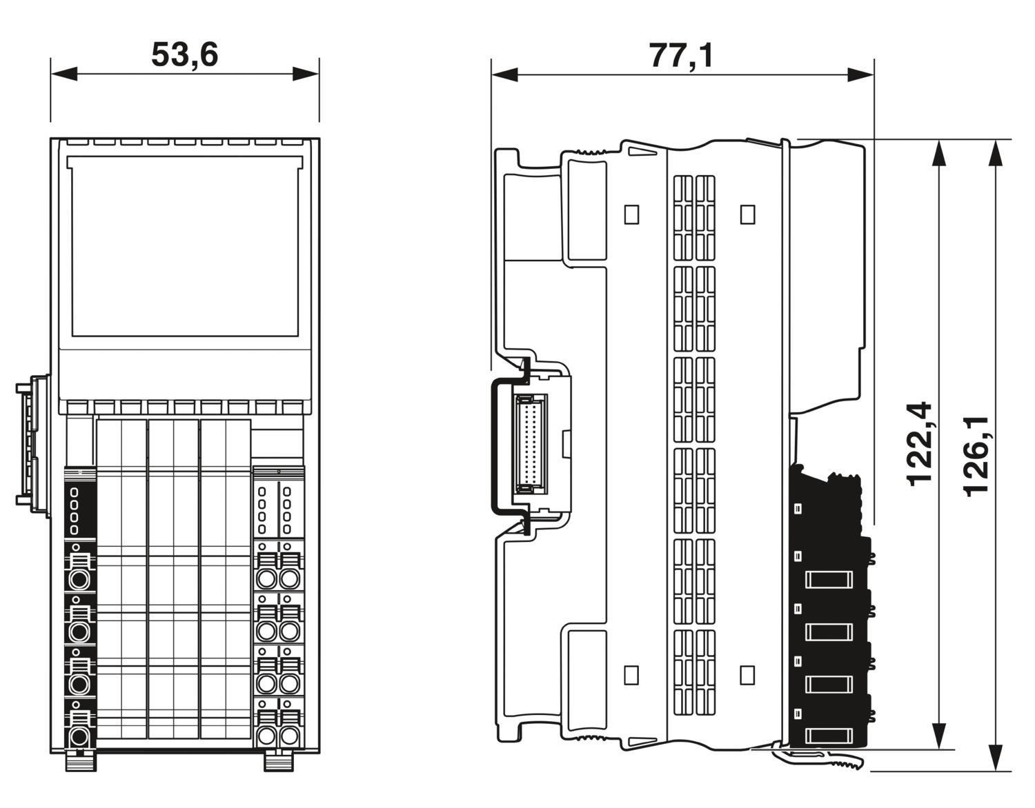
| Width | 53.6 mm |
| Height | 126.1 mm |
| Depth | 77.1 mm |
| Note on dimensions | The depth applies when a TH 35-7.5 DIN rail is used (in accordance with EN 60715). |
| Note on application | |
| Note on application | Only for industrial use |
| Utilization restriction | |
| EMC note | EMC: class A product, see manufacturer's declaration in the download area |
| Utilization restriction | |
| CCCex note | Use in potentially explosive areas is not permitted in China. |
| Axioline F local bus | |
| Number of interfaces | 2 |
| Connection method | Bus base module |
| Transmission speed | 100 Mbps |
| Module | |
| Input address area | 32 Byte (Firmware 1.00) |
| 40 Byte (Firmware 1.02 or later) | |
| Output address area | 8 Byte |
| Required parameter data | 16 Byte |
| Required configuration data | 7 Byte |
| Analog: | |
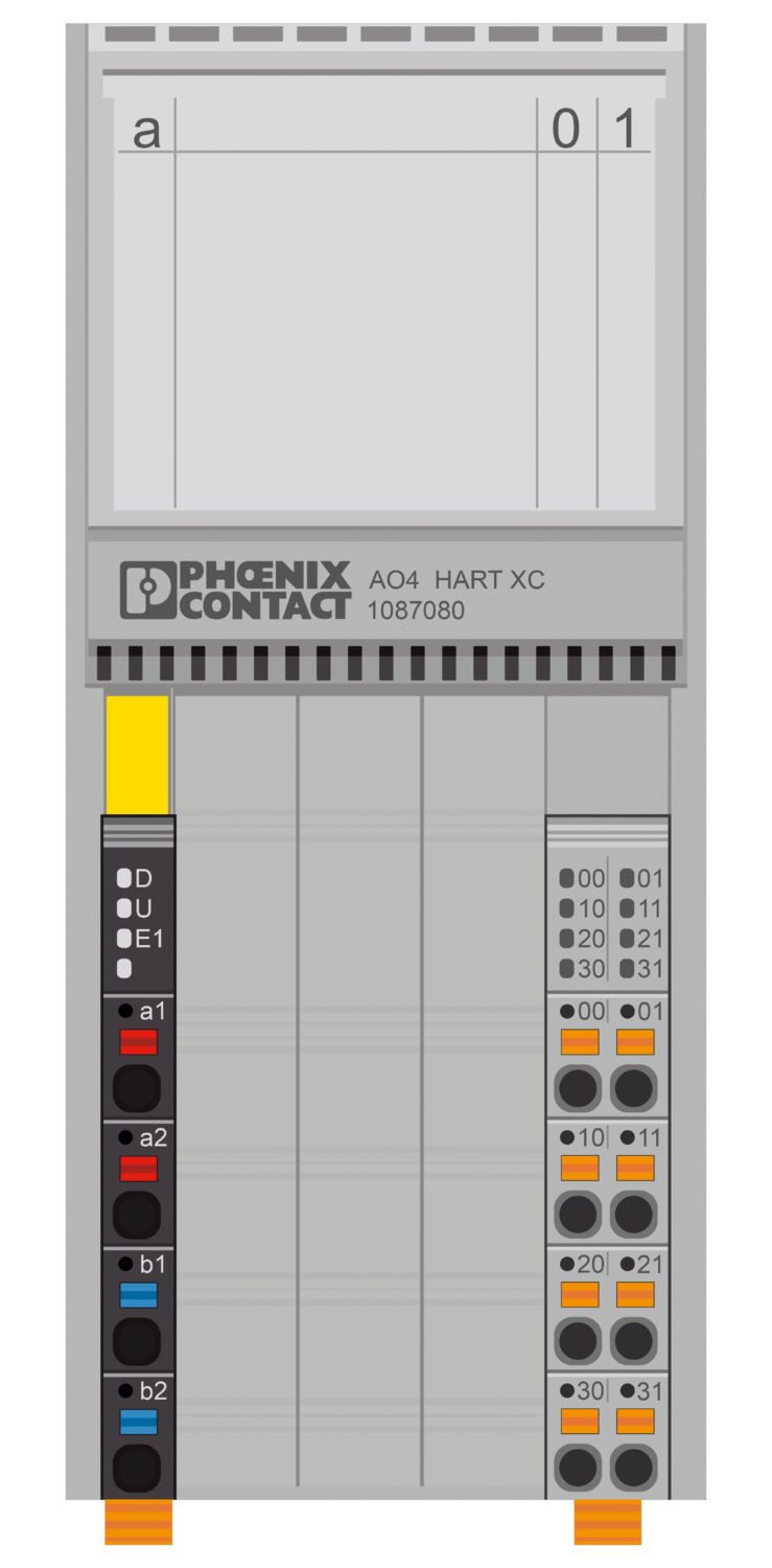
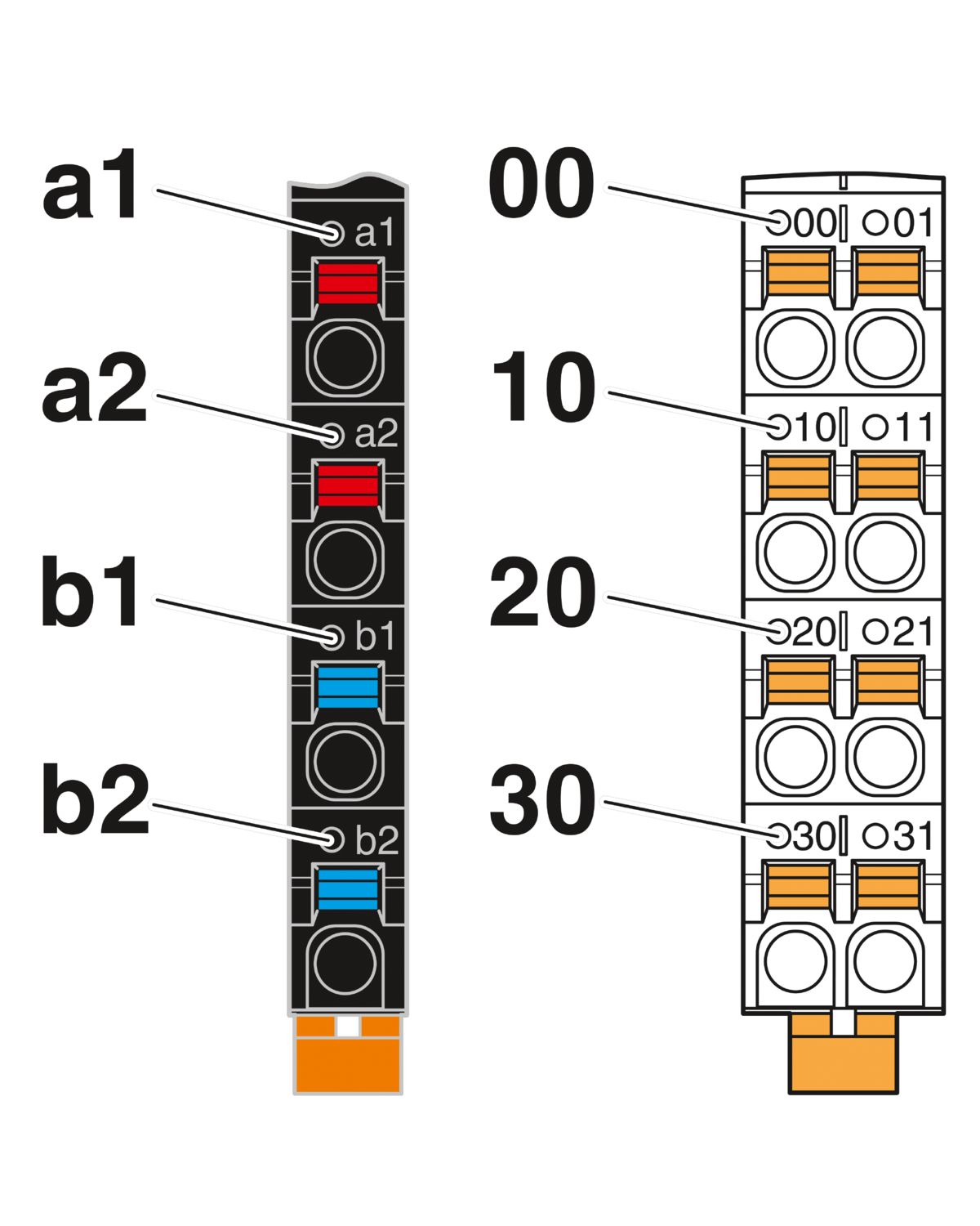
| Output name | Analog outputs |
| Connection method | Push-in connection |
| Connection technology | 2-conductor |
| Note regarding the connection technology | shielded, twisted pair |
| Number of outputs | 4 (HART) |
| D/A converter resolution | 12 bit |
| Protective circuit | Short-circuit and overload protection; electronic |
| Data formats | Inline, S7-compatible, standard formatting |
| Representation of output values | 16 bits (15 bits + sign) |
| Process data update | 1.9 ms (Analog output latency) |
| 400 ms (HART latency per channel) | |
| Current output signal | 0 mA ... 20 mA |
| 4 mA ... 20 mA | |
| Load/output load current output | ≤ 620 Ω (at 20 mA) |
| ≤ 470 Ω (at 23.5157 mA) | |
| Product family | Axioline F |
| Type | block modular |
| Mounting position | any (no temperature derating) |
| Scope of supply | including bus base module and Axioline F connectors |
| Special properties | Extreme conditions version |
| HART functionality | |
| Insulation characteristics | |
| Overvoltage category | II (IEC 60664-1, EN 60664-1) |
| Pollution degree | 2 (IEC 60664-1, EN 60664-1) |
| Maximum power dissipation for nominal condition | 1.98 W |
| Potentials: Axioline F local bus supply (UBus) | |
| Supply voltage | 5 V DC (via bus base module) |
| Current draw | max. 60 mA |
| typ. 40 mA | |
| Potentials: Supply for analog modules (UA) | |
| Supply voltage | 24 V DC |
| Supply voltage range | 19.2 V DC ... 30 V DC (including all tolerances, including ripple) |
| Current draw | max. 150 mA |
| Protective circuit | Surge protection; electronic (35 V, 0.5 s) |
| Reverse polarity protection; Polarity protection diode | |
| Transient protection; Suppressor diode | |
| Electrical isolation/isolation of the voltage ranges | |
| Test voltage: 5 V supply of the local bus (UBus) / 24 V supply (I/Os) | 500 V AC, 60 Hz, 1 min |
| Test voltage: 5 V supply of the local bus (UBus) / functional ground | 500 V AC, 60 Hz, 1 min |
| Test voltage: 5 V supply of the local bus (UBus) / analog outputs | 1500 V AC, 60 Hz, 1 min |
| Test voltage: 24 V supply (I/O) / functional ground | 500 V AC, 60 Hz, 1 min |
| Test voltage: 24 V supply (I/O) / analog outputs | 1500 V AC, 60 Hz, 1 min |
| Test voltage: Analog outputs/functional ground | 500 V AC, 60 Hz, 1 min |
| Connection technology | |
| Connection name | Axioline F connector |
| Note on the connection method | Please observe the information provided on conductor cross-sections in the “Axioline F: system and installation” user manual. |
| Conductor connection | |
| Connection method | Push-in connection |
| Conductor cross-section rigid | 0.2 mm² ... 1.5 mm² |
| Conductor cross-section flexible | 0.2 mm² ... 1.5 mm² |
| Conductor cross-section AWG | 24 ... 16 |
| Stripping length | 8 mm |
| Axioline F connector | |
| Connection method | Push-in connection |
| Note on the connection method | Please observe the information provided on conductor cross-sections in the “Axioline F: system and installation” user manual. |
| Conductor cross-section, rigid | 0.2 mm² ... 1.5 mm² |
| Conductor cross-section, flexible | 0.2 mm² ... 1.5 mm² |
| Conductor cross-section AWG | 24 ... 16 |
| Stripping length | 8 mm |
| Ambient conditions | |
| Ambient temperature (operation) | -25 °C ... 60 °C (Standard) |
| -40 °C ... 70 °C (Extended, see section “Tested successfully: use under extreme ambient conditions” in the data sheet.) | |
| Degree of protection | IP20 |
| Air pressure (operation) | 70 kPa ... 106 kPa (up to 3000 m above sea level) |
| Air pressure (storage/transport) | 70 kPa ... 106 kPa (up to 3000 m above sea level) |
| Ambient temperature (storage/transport) | -40 °C ... 85 °C |
| Permissible humidity (operation) | 5 % ... 95 % (non-condensing) |
| Permissible humidity (storage/transport) | 5 % ... 95 % (non-condensing) |
| Protection class | III (IEC 61140, EN 61140, VDE 0140-1) |
| ATEX | |
| Identification | II 3G Ex ec IIC T4 Gc |
| Certificate | DEMKO 20 ATEX 2334X |
| IECEx | |
| Identification | Ex ec IIC T4 Gc |
| Certificate | IECEx UL 20.0002X |
| UKCA Ex (UKEX) | |
| Identification | II 3G Ex ec IIC T4 Gc |
| Certificate | PxCAI22UKEx1052427X |
| UL, USA/Canada | |
| Identification | cULus |
| Certificate | E238705 |
| UL Ex, USA / Canada | |
| Identification | Class I, Division 2, Groups A, B, C, D, T4 |
| Class I, Zone 2, IIC T4 | |
| Certificate | E196811 |
| CCC / China-Ex | |
| Identification | Ex ec IIC T4 Gc |
| Mounting type | DIN rail mounting |
| Mounting position | any (no temperature derating) |
IECEx
Approval ID: IECEx UL 20.0002XcUL Listed
Approval ID: E196811UL Listed
Approval ID: E196811ATEX
Approval ID: DEMKO 20 ATEX 2334X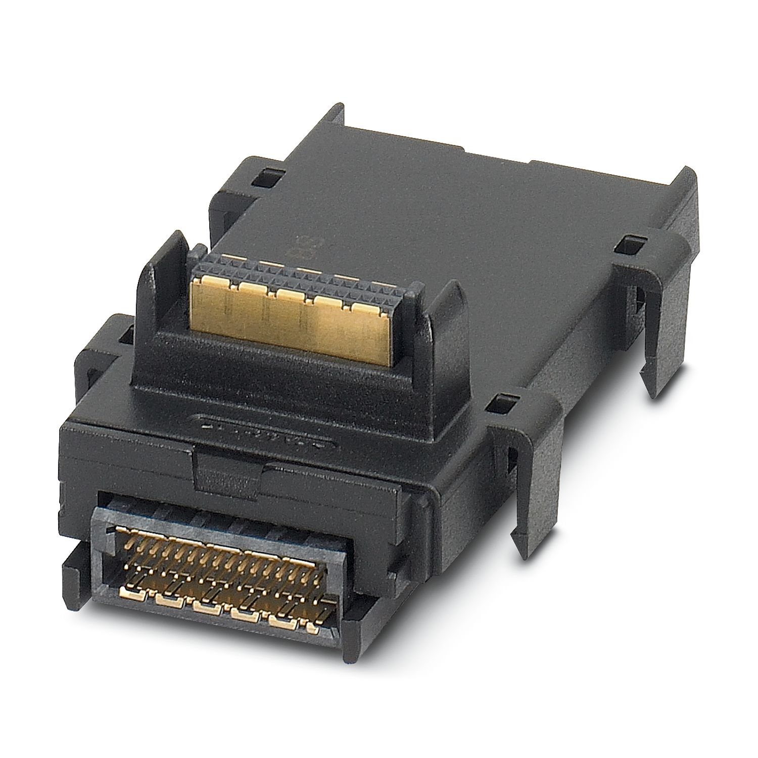
Your advantages
4 analog output-powered control signals for HART
Current range: 4 mA ... 20 mA and 0 mA ... 20 mA
Cyclic access to PV, SV, TV, QV, and Loop Current
Can be used under extreme ambient conditions
Extended temperature range of -40 °C ... +70 °C (see “Tested successfully: use under extreme ambient conditions” in the data sheet)