
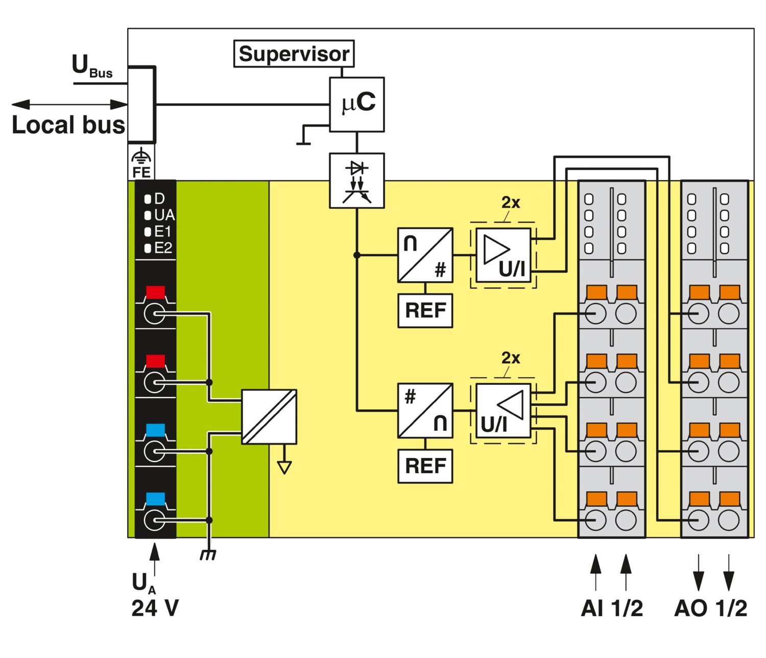
The module is designed for use within an Axioline F station. It is used to acquire and output analog voltage and current signals.
AXL F AI2 AO2 XC 1H
-
Analog module
1035429
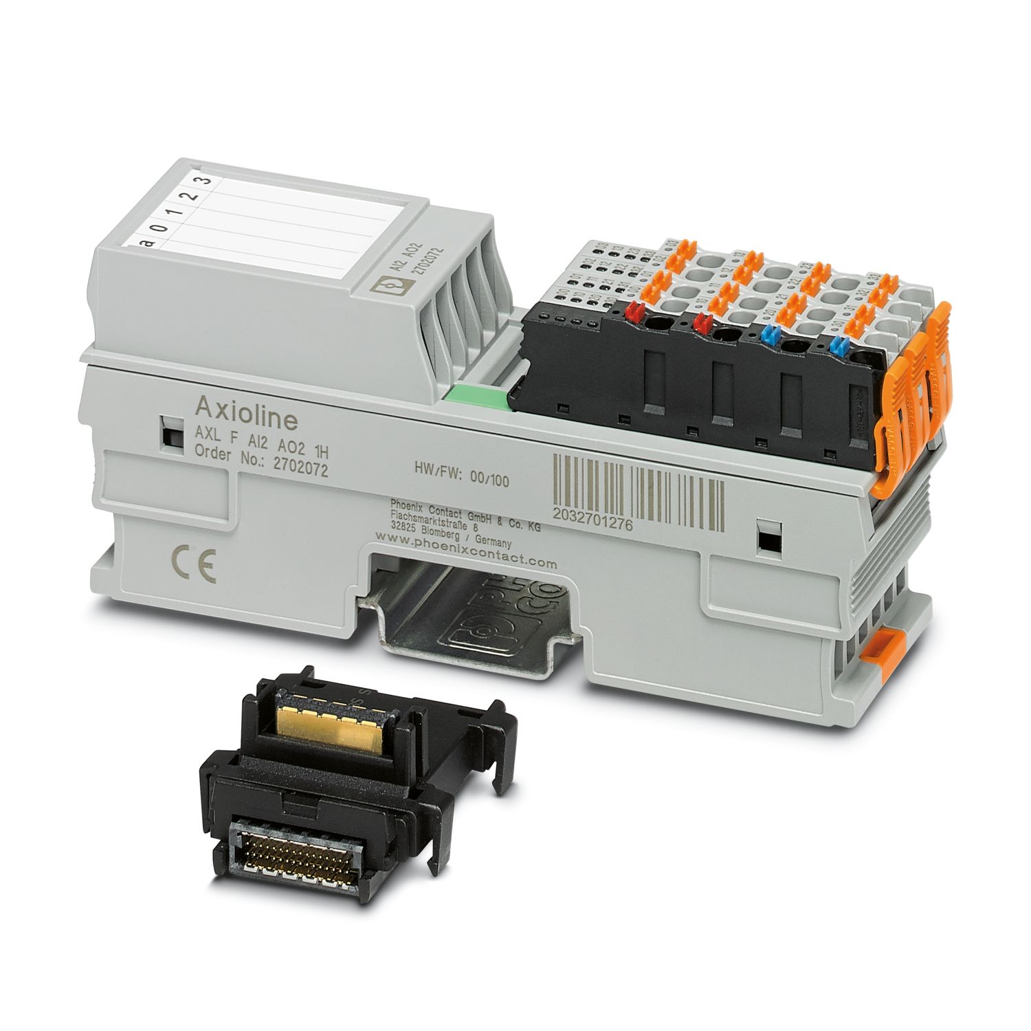
Axioline F, Analog I/O module, Analog inputs: 2, 0 V ... 5 V, -5 V ... 5 V, 0 V ... 10 V, -10 V ... 10 V, 0 mA ... 20 mA, 4 mA ... 20 mA, -20 mA ... 20 mA, connection technology: 2-conductor, Analog outputs: 2, 0 V ... 5 V, -5 V ... 5 V, 0 V ... 10 V, -10 V ... 10 V, 0 mA ... 20 mA, 4 mA ... 20 mA, -20 mA ... 20 mA, connection technology: 2-conductor, transmission speed in the local bus: 100 Mbps, Extreme conditions version, degree of protection: IP20, including bus base module and Axioline F connectors
Free download available.
Downloads
Product details
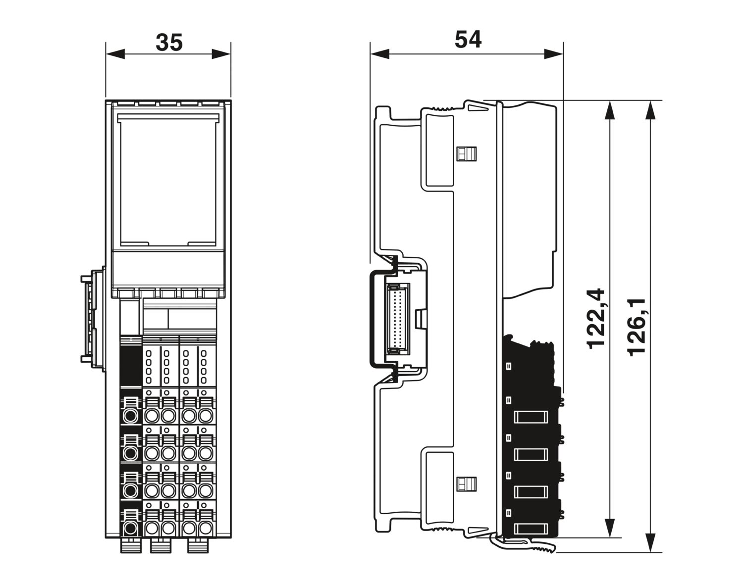
| Dimensional drawing |
|
| Width | 35 mm |
| Height | 126.1 mm |
| Depth | 54 mm |
| Note on dimensions | The depth applies when a TH 35-7.5 DIN rail is used (in accordance with EN 60715). |
| Note on application | |
| Note on application | Only for industrial use |
| Axioline F local bus | |
| Number of interfaces | 2 |
| Connection method | Bus base module |
| Transmission speed | 100 Mbps |
| Module | |
| Input address area | 4 Byte |
| Output address area | 4 Byte |
| Required parameter data | 11 Byte |
| Required configuration data | 7 Byte |
| Analog: General | |
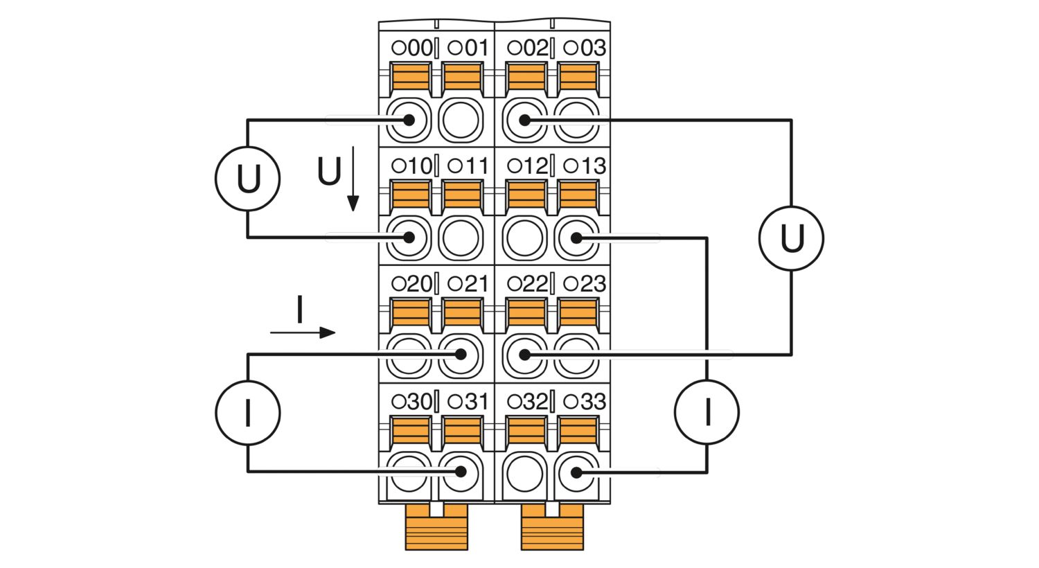
| Input name | Analog inputs |
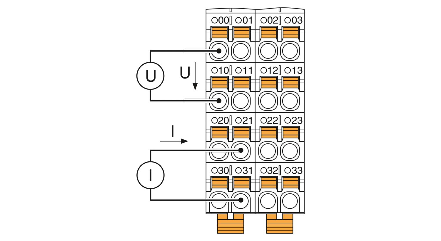
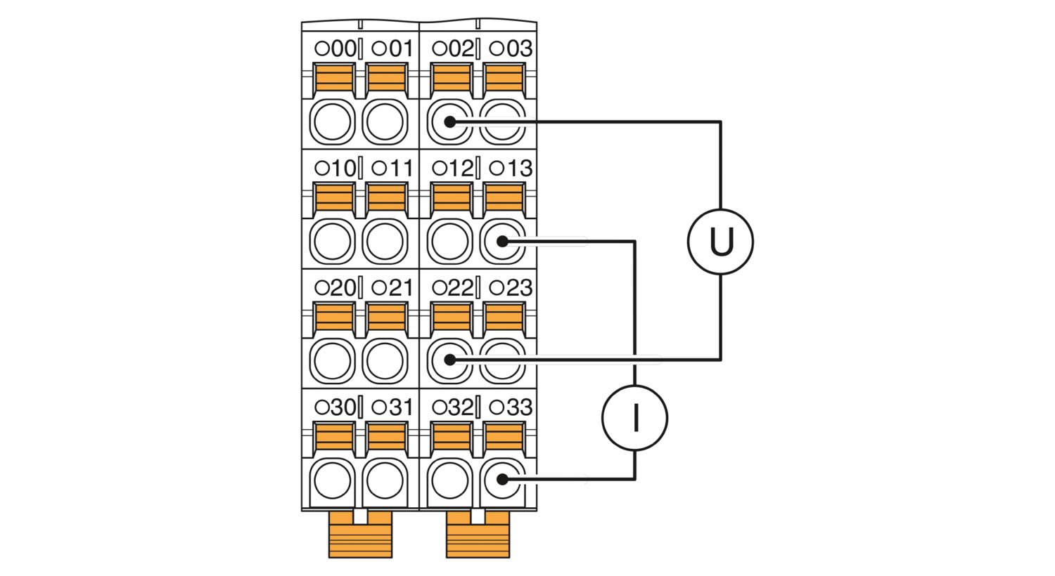
| Description of the input | Differential inputs, voltage or current can be chosen separately |
| Number of inputs | 2 |
| A/D conversion time | 2 µs |
| A/D converter resolution | 16 bit |
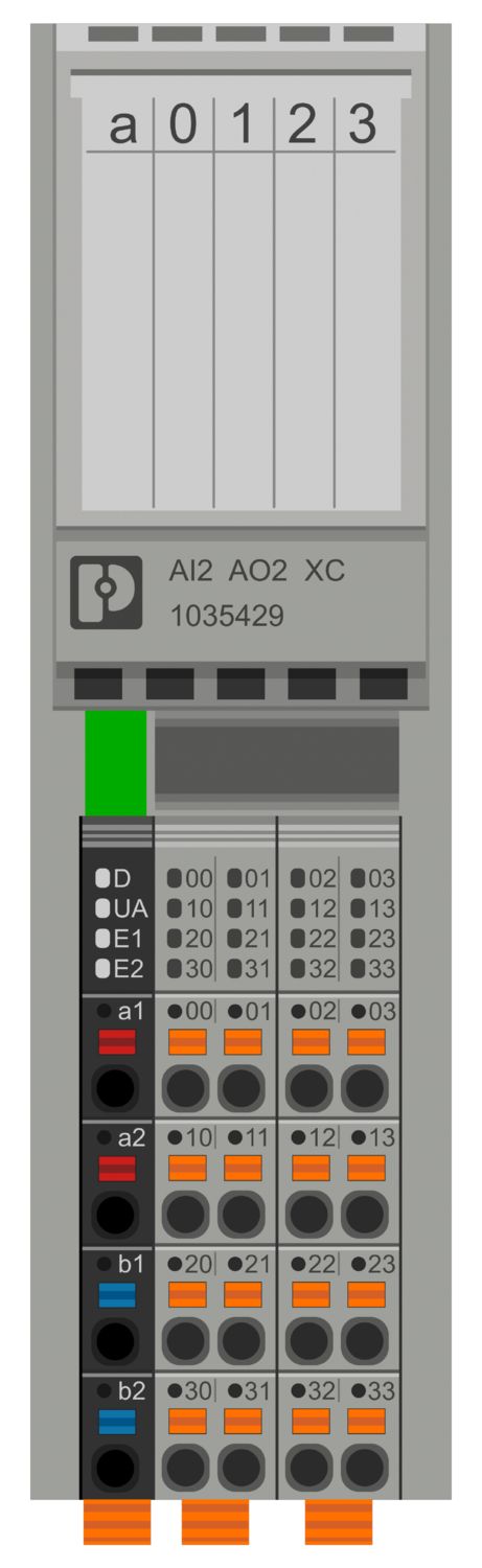
| Connection method | Push-in connection |
| Connection technology | 2-conductor |
| Note regarding the connection technology | shielded, twisted pair |
| Current input signal | 0 mA ... 20 mA |
| 4 mA ... 20 mA | |
| -20 mA ... 20 mA | |
| Input resistance current input | 104 Ω (typical) |
| Voltage input signal | 0 V ... 5 V |
| -5 V ... 5 V | |
| 0 V ... 10 V | |
| -10 V ... 10 V | |
| Input resistance of voltage input | 268 kΩ (typical) |
| Data formats | IB IL, S7-compatible, standardized representation |
| Input filter | 30 Hz, 12 kHz and mean value generation (can be parameterized) |
| Limit frequency (3 dB) | 30 Hz |
| 12 kHz | |
| Common mode voltage range signal - ground | -50 V DC ... 50 V DC |
| Measured value representation | 16 bits (15 bits + sign bit) |
| Protective circuit | Transient protection of inputs; Suppressor diode |
| Overload protection of the current inputs; No; ±5.2 V DC, maximum, Imax = 50 mA | |
| Overload protection of the voltage inputs; ±30 V DC, maximum | |
| Analog: | |
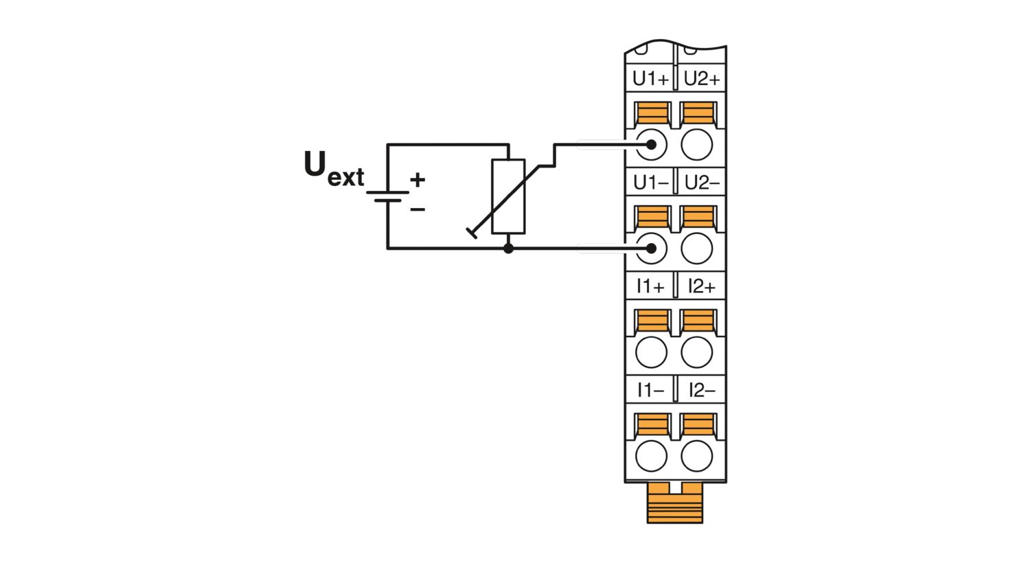
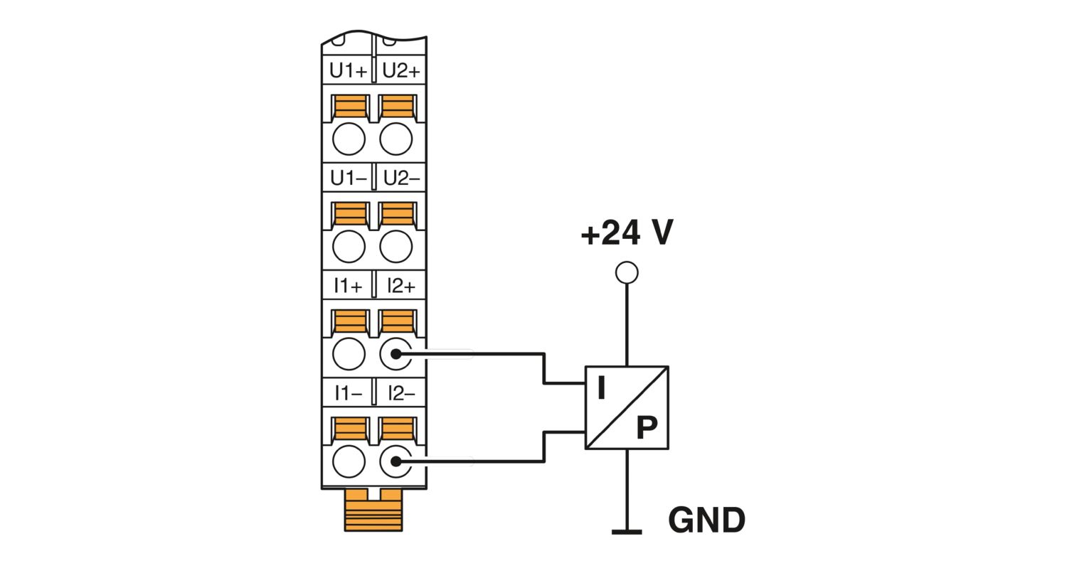
| Output name | Analog outputs |
| Connection method | Push-in connection |
| Connection technology | 2-conductor |
| Note regarding the connection technology | shielded, twisted pair |
| Number of outputs | 2 |
| D/A converter resolution | 16 bit |
| Protective circuit | Short-circuit and overload protection; electronic |
| Transient protection; Suppressor diode | |
| Data formats | IB IL, S7-compatible, standardized representation |
| Representation of output values | 16 bits (15 bits + sign) |
| Process data update | 150 µs |
| Current output signal | 0 mA ... 20 mA |
| 4 mA ... 20 mA | |
| -20 mA ... 20 mA | |
| Load/output load current output | ≤ 500 Ω |
| Voltage output signal | 0 V ... 5 V |
| -5 V ... 5 V | |
| 0 V ... 10 V | |
| -10 V ... 10 V | |
| Load/output load voltage output | ≥ 2 kΩ |
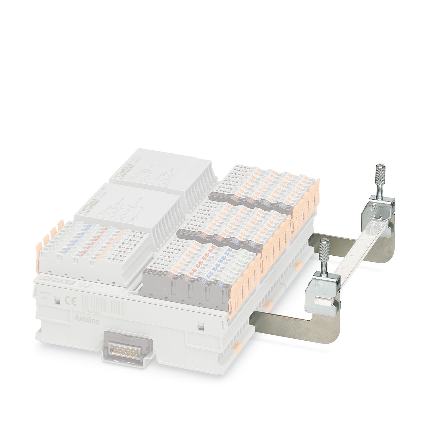
| Product family | Axioline F |
| Type | block modular |
| Mounting position | any (no temperature derating) |
| Scope of supply | including bus base module and Axioline F connectors |
| Special properties | Extreme conditions version |
| Insulation characteristics | |
| Overvoltage category | II (IEC 60664-1, EN 60664-1) |
| Pollution degree | 2 (IEC 60664-1, EN 60664-1) |
| Maximum power dissipation for nominal condition | 2.75 W |
| Potentials: Axioline F local bus supply (UBus) | |
| Supply voltage | 5 V DC (via bus base module) |
| Current draw | max. 150 mA |
| typ. 120 mA | |
| Potentials: Supply for analog modules (UA) | |
| Supply voltage | 24 V DC |
| Supply voltage range | 19.2 V DC ... 30 V DC (including all tolerances, including ripple) |
| Current draw | max. 80 mA (2 current channels, 24 mA output, 500 Ω load) |
| typ. 40 mA | |
| max. 60 mA (2 voltage channels, 10 V output, 2 kΩ load) | |
| Protective circuit | Surge protection; electronic (35 V, 0.5 s) |
| Reverse polarity protection; Polarity protection diode | |
| Transient protection; Suppressor diode | |
| Electrical isolation/isolation of the voltage ranges | |
| Test voltage: 5 V supply of the local bus (UBus) / 24 V supply (I/Os) | 500 V AC, 50 Hz, 1 min |
| Test voltage: 5 V supply of the local bus (UBus) / analog inputs and outputs | 500 V AC, 50 Hz, 1 min |
| Test voltage: 5 V supply of the local bus (UBus) / functional ground | 500 V AC, 50 Hz, 1 min |
| Test voltage: 24 V supply (I/O) / analog inputs and outputs | 500 V AC, 50 Hz, 1 min |
| Test voltage: 24 V supply (I/O) / functional ground | 500 V AC, 50 Hz, 1 min |
| Test voltage: Analog inputs and outputs/functional ground | 500 V AC, 50 Hz, 1 min |
| Connection technology | |
| Connection name | Axioline F connector |
| Note on the connection method | Please observe the information provided on conductor cross-sections in the “Axioline F: system and installation” user manual. |
| Applications with UL approval: only use copper conductors. | |
| Conductor connection | |
| Connection method | Push-in connection |
| Conductor cross-section rigid | 0.2 mm² ... 1.5 mm² |
| Conductor cross-section flexible | 0.2 mm² ... 1.5 mm² |
| Conductor cross-section AWG | 24 ... 16 |
| Stripping length | 8 mm |
| Axioline F connector | |
| Connection method | Push-in connection |
| Note on the connection method | Please observe the information provided on conductor cross-sections in the “Axioline F: system and installation” user manual. |
| Applications with UL approval: only use copper conductors. | |
| Conductor cross-section, rigid | 0.2 mm² ... 1.5 mm² |
| Conductor cross-section, flexible | 0.2 mm² ... 1.5 mm² |
| Conductor cross-section AWG | 24 ... 16 |
| Stripping length | 8 mm |
| Ambient conditions | |
| Ambient temperature (operation) | -25 °C ... 60 °C (Standard applications and applications with UL approval) |
| -40 °C ... 70 °C (Extended, see section “Tested successfully: use under extreme ambient conditions” in the data sheet.) | |
| Degree of protection | IP20 |
| Air pressure (operation) | 70 kPa ... 106 kPa (up to 3000 m above sea level) |
| Air pressure (storage/transport) | 70 kPa ... 106 kPa (up to 3000 m above sea level) |
| Ambient temperature (storage/transport) | -40 °C ... 85 °C |
| Permissible humidity (operation) | 5 % ... 95 % (non-condensing) |
| Permissible humidity (storage/transport) | 5 % ... 95 % (non-condensing) |
| Test (noxious gas) | |
| Test standard | ISA-71.04-2013 G3 Harsh Group A |
| IEC 60068-2-60:2015 Method 4 | |
| Temperature | 25 °C ±1 K |
| Humidity (relative) | 75 % ±3 % |
| Test duration | 21 Days |
| Volume concentration H2S (Hydrogen sulfide) | 50 ppb |
| Volume concentration NO2 (Nitrogen dioxide) | 1250 ppb |
| Volume concentration Cl2 (Chlorine) | 10 ppb |
| Volume concentration SO2 (Sulfur dioxide) | 300 ppb |
| Protection class | III (IEC 61140, EN 61140, VDE 0140-1) |
| Mounting type | DIN rail mounting |
| Mounting position | any (no temperature derating) |
cULus Listed
Approval ID: E238705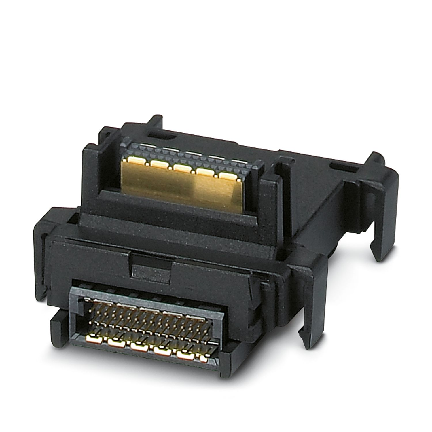
Your advantages
2 analog differential input channels
Connection of sensors in 2-conductor technology
Current ranges: 0 mA ... 20 mA, 4 mA ... 20 mA, ±20 mA
Voltage ranges: 0 V ... 10 V, ±10 V, 0 V ... 5 V, ±5 V
2 analog outputs
Connection of actuators in 2-conductor technology
Current ranges: 0 mA ... 20 mA, 4 mA ... 20 mA, ±20 mA
Voltage ranges: 0 V ... 10 V, ±10 V, 0 V ... 5 V, ±5 V
Process data update < 150 µs
Device rating plate stored
Can be used under extreme ambient conditions
Extended temperature range of -40 °C ... +70 °C (see “Tested successfully: use under extreme ambient conditions” in the data sheet)
Partially coated PCBs