
CAPAROC
-
Electronic circuit breaker
1290013
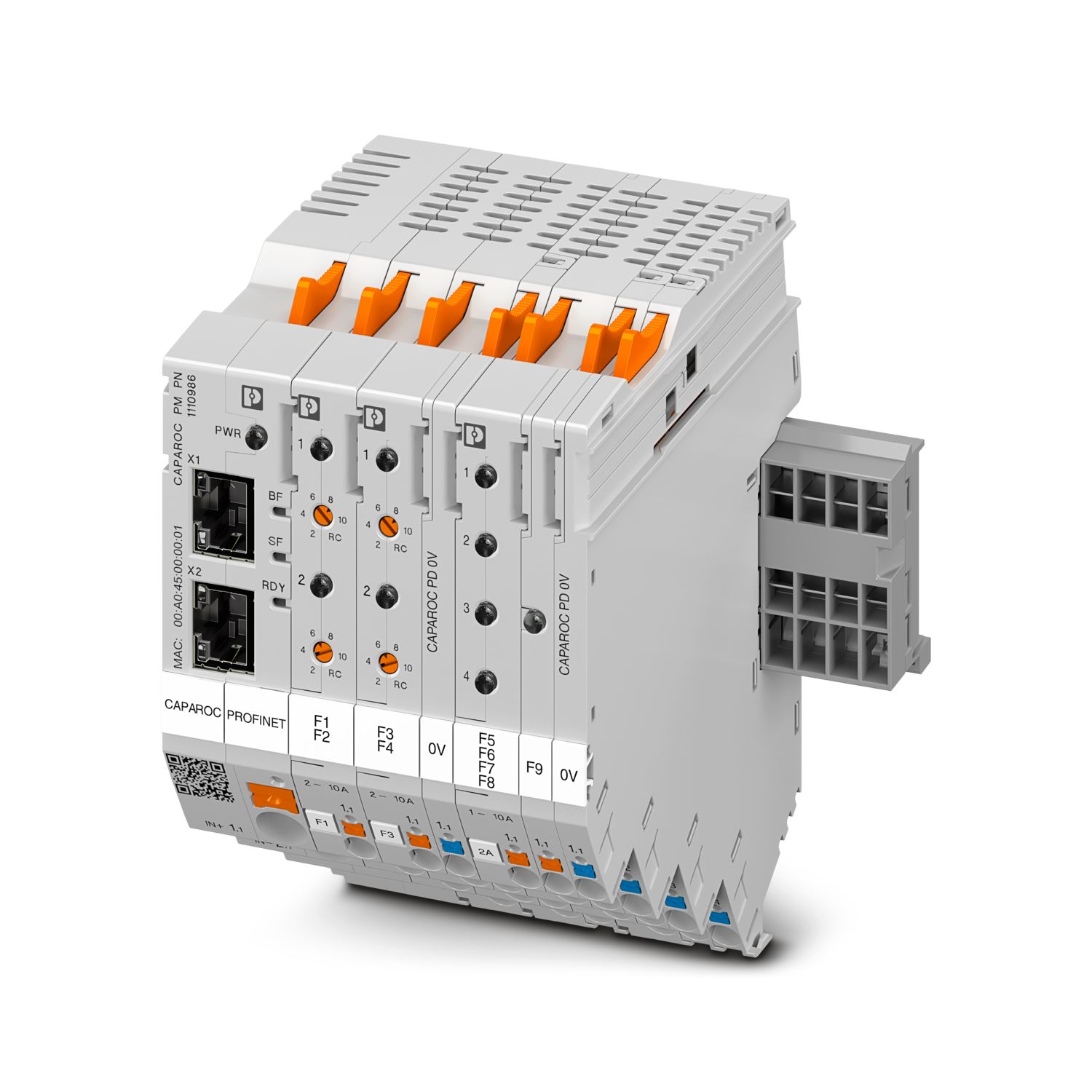
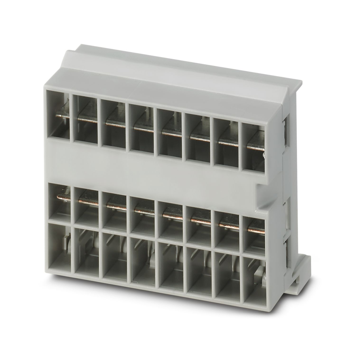
Customizable electronic circuit breaker system for protecting loads at 12 and 24 V DC. Configured from power modules, circuit breakers, and potential distributor modules. For DIN rail installation via the CAPAROC current rails.
Product details
Your advantages
The customizable standard, thanks to a wide range of possible combinations of the future-proof modular system
Easy operation for everyone through tool-free assembly, uninterrupted installation, and transparent operating state
Strikingly simple design-in with extensive support from the selection up to digital services
Frequently asked questions
Why does the power LED (PWR) of the CAPAROC PM IOL flash red?
A red flashing of the power LED on the IO-Link power module indicates a changed hardware configuration. When commissioning for the first time, this warning can be acknowledged without hesitation by pressing the button for longer (> 2 seconds).
...
View more
A red flashing of the power LED on the IO-Link power module indicates a changed hardware configuration. When commissioning for the first time, this warning can be acknowledged without hesitation by pressing the button for longer (> 2 seconds).
If this warning is displayed while the process is running, the hardware configuration has changed since the last acknowledgement and should be checked. If the number of channels in a module is increased due to a previous module replacement, acknowledging the warning will inevitably result in a shift in the process data.
How many fused outgoing circuits do the circuit breaker modules have?
CAPAROC 1-channel modules have four connection points with the same fused potential.
CAPAROC 2-channel modules have two connection points per channel.
CAPAROC 4-channel modules have one connection point per channel.
Is there a hardware tutorial in which the CAPAROC functions are explained?
How many circuit breaker modules can I connect downstream of an infeed module?
CAPAROC PM S-R: 20 circuit breaker modules
CAPAROC PM IOL: 20 channels
CAPAROC PM PN: 16 circuit breaker modules
CAPAROC PM EIP: 16 circuit breaker modules
CAPAROC PM MB: 16 circuit breaker modules
CAPAROC PM EC: 16 circuit breaker modules
The channel LED flashes yellow twice every 4 seconds. What does this mean?
This means that the internal communication to the power module is interrupted or faulty.
Check that the modules are mounted correctly and that there is no gap between the modules. If communication is still disrupted, check the side contacts of the...
View more
This means that the internal communication to the power module is interrupted or faulty.
Check that the modules are mounted correctly and that there is no gap between the modules. If communication is still disrupted, check the side contacts of the first module (left) that is flashing, if they are bent, either too far into the module, not centered in the housing opening or otherwise damaged, replace the module.
Can I block the setting of the set currents?
The currents can be locked in different ways:
1. Programming lock: press the PWR button on the power module for > 3 seconds, the PWR LED flashes yellow 3 x, the settings are now locked. Pressing it again for > 3 seconds causes the LED to fla...
View more
The currents can be locked in different ways:
1. Programming lock: press the PWR button on the power module for > 3 seconds, the PWR LED flashes yellow 3 x, the settings are now locked. Pressing it again for > 3 seconds causes the LED to flash green 3 times and unlocks it again.
2. The lock can also be set and released via the communication interface; the operating lock can also be set here, which prevents operation and settings on the device. The lock can then only be released via the interface.
What signals does the CAPAROC PM S-R power module provide?
The module has three different connection options for the signals:
S - Status output: Potential-bound collective signal, this indicates the status of the system. If there is at least one fault shutdown, this outputs a message.
High (24 V) ...
View more
The module has three different connection options for the signals:
S - Status output: Potential-bound collective signal, this indicates the status of the system. If there is at least one fault shutdown, this outputs a message.
High (24 V) = there is no fault
Low (0 V) = there is at least one fault shutdown
Maximum current 20 mA
RST - Reset input: Channels that have been switched off by an error are switched on again via a falling edge.
I > 80%-signal output: Potential-bound collective signal, if the current flowing on a channel is greater than 80% of the set nominal current, a HIGH signal (24 V) is out