Mounting and removing modules
Safety notes for mounting and removal
![]() WARNING: Dangerous contact voltage
WARNING: Dangerous contact voltage
Only qualified personnel may do this work. The personnel must be familiar with the necessary safety precautions.
![]() WARNING: Dangerous contact voltage in the event of ground faults
WARNING: Dangerous contact voltage in the event of ground faults
The CAPAROC modules for the low-voltage area must only be operated in grounded networks.
![]() NOTE: Electrostatic discharge
NOTE: Electrostatic discharge
The modules contain components that can be damaged or destroyed by electrostatic discharge. When handling the device, observe the necessary safety precautions against electrostatic discharge (ESD) in accordance with EN 61340-5-1 and IEC 61340-5-1.
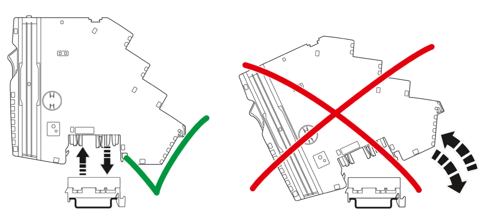
![]() NOTE: Damage to the contacts when tilting
NOTE: Damage to the contacts when tilting
Tilting the modules can damage the contacts.
– Place the modules vertically onto the current rail.
– Remove the modules vertically from the current rail.
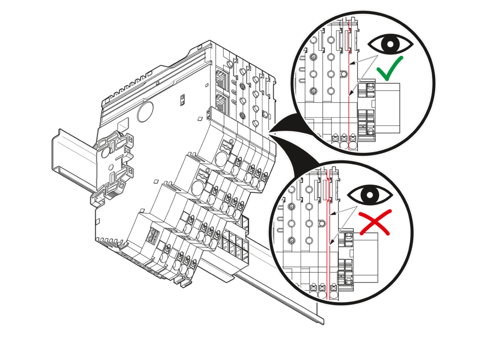
![]() NOTE: No internal module communication
NOTE: No internal module communication
When connecting to the side, make sure that the module fits exactly in the guide of the adjacent module.
 Additionally observe the information in the module-specific data sheets.
Qualified personnel
In terms of this user manual, qualified personnel are persons who, because of their education, experience and instruction, and their knowledge of relevant standards, regulations, accident prevention, and service conditions, have been authorized to carry out any required operations, and who are able to recognize and avoid any possible dangers. See Section Qualification of users.
Basic information about mounting
Mounting location
The CAPAROC modules meet the requirements of IP20 degree of protection. They are intended for use in closed control cabinets or control boxes (junction boxes) with IP54 degree of protection in accordance with EN 60529 or higher.
DIN rail
Mount the CAPAROC modules on a 35 mm standard DIN rail. The preferred installed height of the DIN rail is 7.5 mm (corresponds to TH 35-7.5 in accordance with EN 60715).
Mount the modules vertically on the DIN rail. As the module does not need to be tilted, easy installation and removal is ensured even in confined spaces.
Mounting position
Wall mounting on a horizontal DIN rail on the wall is the preferred mounting position. This mounting position provides optimum air flow for the modules.
End brackets
Mount end brackets on both sides of the CAPAROC modules. The end brackets ensure that the CAPAROC system is correctly mounted on the DIN rail. They secure it on both sides and keep it from moving from side to side on the DIN rail.
Always attach the left end bracket of the system when beginning to mount the system. This ensures the following:
- It prevents the system from slipping on the DIN rail.
- The space for the end bracket is secured.
- When connecting additional modules and current rails, the system does not slip on the
- DIN rail.
Tools
No tools are required for mounting the modules.
A standard tool, e.g., a bladed screwdriver with a blade width of 2.5 mm, is necessary for removing the current rail and actuating the spring levers.
Order of the modules
After the power module, the modules can be installed in any order on the DIN rail. To ensure functionality, mount the modules side by side, without a gap.
- To ensure connection to the internal bus system, mount the modules to the right of the power module.
- Modules that are to the left of the power module have no connection to the internal bus system. They have no connection to the internal remote singaling and cannot be used for functions supported on the bus side.
Maximum number of modules
The maximum number of CAPAROC circuit breaker modules depends on the power module used.
For the maximum number, please refer to the table below and the relevant power module data sheet.
| Power module | Description | Max number |
| CAPAROC PM PN | Power module with Profinet | 16 modules |
| CAPAROC PM EIP | Power module with EtherNet/IP™ interface | 16 modules |
| CAPAROC PM S-R | Power module with status-reset | 20 modules |
| CAPAROC PM IOL | Power module with IO-Link |
20 channel |
Mounting the modules
Please refer to Section Safety notes for mounting and removal.
No tools are required to mount the CAPAROC system.
Mounting the current rail
- First, mount the end bracket on the DIN rail.
- Then install the current rail on the DIN rail.
- Use an appropriately sized current rail for the application.
- If one current rail is not enough, you can extend it with an additional current rail.
- To connect them, insert the next current rail in the connection of the preceding one.
Current rails are available with different overall widths. Select the appropriate length for your application from the overview in Section CAPAROC current rails.
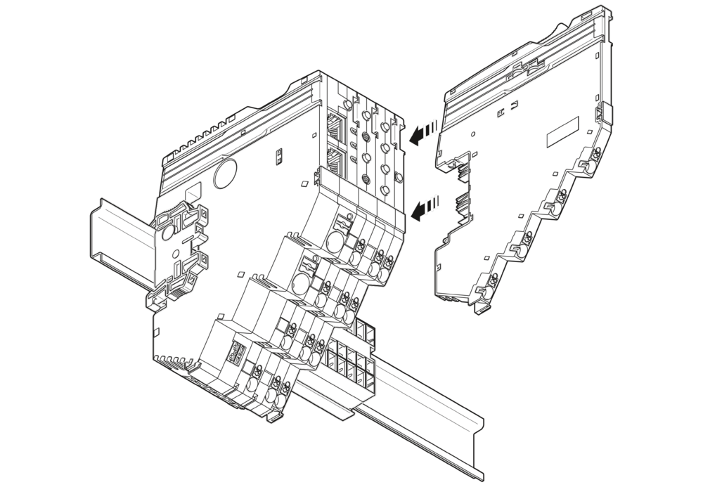
Snapping on the modules
Place the power module and circuit breaker modules vertically onto the current rail and DIN rail until they snap into place. Make sure that the device plugs for the current rail are positioned above the corresponding opening on the current rail. Use the guide slots on the housing sides to connect the modules together.
Removing the modules
![]() NOTE: Set the channels to the no-load state on the module that is to be replaced before changing it.
NOTE: Set the channels to the no-load state on the module that is to be replaced before changing it.
Please refer to Section Safety notes for mouning and removal.
A standard tool, e.g., a bladed screwdriver with a blade width of 2.5 mm, is necessary for removing the modules.
Removing the cables
See Removing the cables.
Removing the module
Actuate the release mechanism to remove the power module and the circuit breaker modules. It is located on the top of the modules (orange lever). You can then remove the modules vertically from the current rail while the release mechanism is actuated.
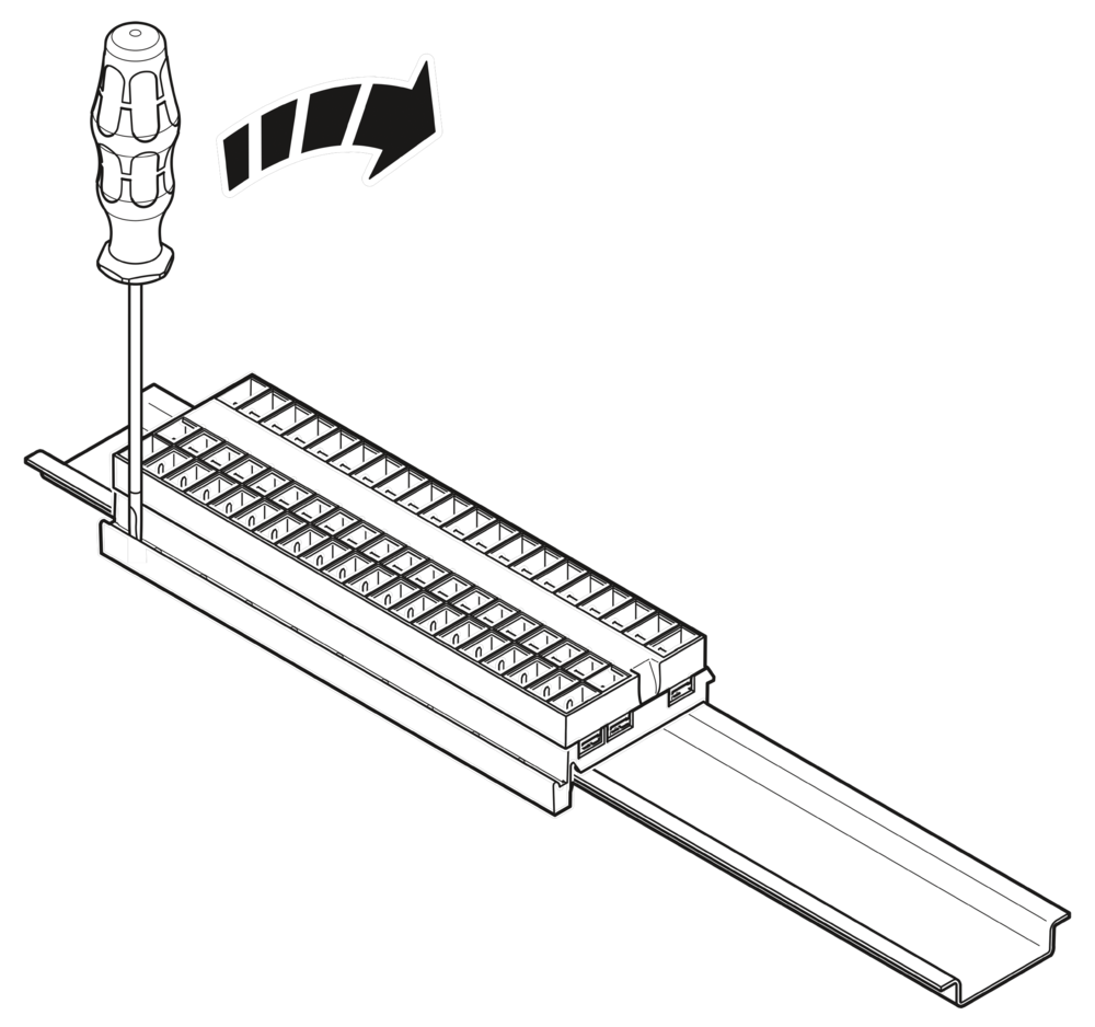
Removing the current rail
To remove the current rail from the DIN rail, use a screwdriver to release the latching via the slot on the side of the current rail. Depending on the current rail used, repeat this step several times from left to right. Then remove the current rail from the DIN rail.
Replacing a module
- To replace a module, proceed as described in Sections Removing the modules and Mounting the modules.
- Following replacement, make sure that all cables are connected correctly and securely again.
Due to the rear current rail, modules can also be replaced during operation. The load circuit of the other modules is not interrupted. Only the internal bus system is interrupted. After successfully mounting a new identical module, communication is automatically restored and the system does not need to be restarted.
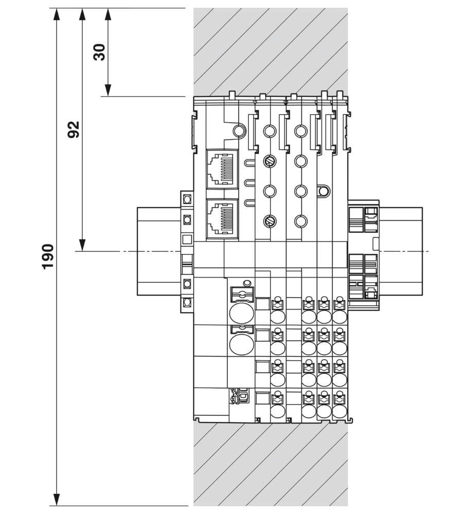
Mounting distances
Leave enough space below the system to connect all the cables.
Maintain a minimum distance of 30 mm above and below to ensure adequate convection cooling.