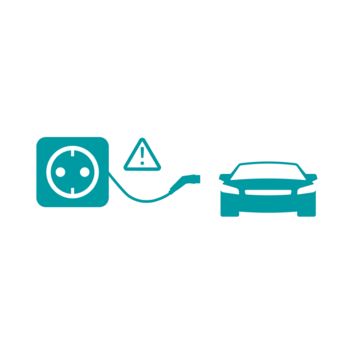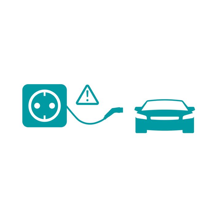
The vehicle is charged with AC power from a household outlet. Voltages up to 250 V may be applied in single-phase grids, and up to 480 V in three-phase grids. The maximum charging current is 16 A. There is no communication between the vehicle and the charging point. Fuse protection via a residual current device (RCD) is a mandatory requirement. Because this is not always guaranteed in older installations, Phoenix Contact advises against this charging mode.
Principles of e-mobility charging technology Electric vehicles are charged according to different country-specific conditions. We convey the basic knowledge in a clear and understandable way.
What charging standards are there? Overview of the common connector types
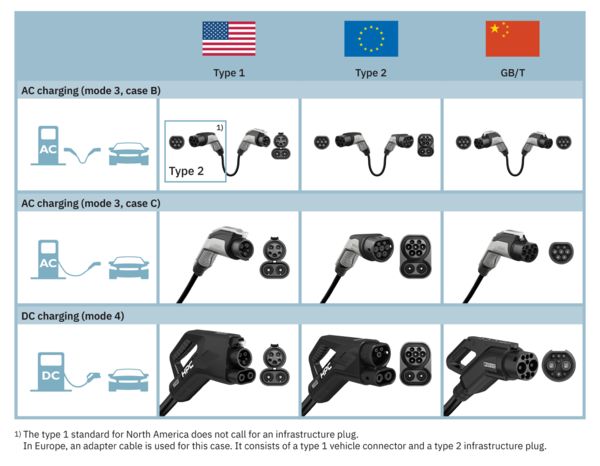
Originating in North America, Europe, and China, three charging standards with their own specific geometries for charging connectors and charging sockets have become established internationally. In addition, the connector for AC charging (mode 3, cases B and C) has a different design than the one for DC charging (mode 4). Our broad CHARX portfolio covers all use cases:
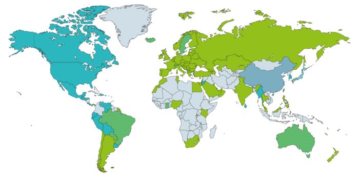
Where does which charging standard apply? The current prevalence on the world map
AC and DC charging: What is the difference? And what is recommended in which situation?
AC charging
The alternating current (AC) from the supply network first flows into the vehicle via the charging station and charging cable – controlled, but without conversion. Only an AC/DC converter installed in the vehicle, the so-called onboard charger, converts it into direct current (DC), which can be used to charge the battery. Because AC charging stations therefore do not require conversion electronics, they are usually less expensive than DC charging stations and more attractive for private applications. Depending on the charging station, charging cable, and onboard charger, charging powers of up to 22 kW can be achieved. Due to these comparatively low powers, AC charging is gentler on the battery and is always recommended when the vehicle is parked for longer than 30 minutes – for example, overnight in a carport, garage, or at a hotel, and during the day at restaurants and supermarkets.
DC charging
Here, the power contacts and cable cross-sections of the charging connector are larger than for AC charging. Significantly higher charging powers of up to 500 kW (High Power Charging, HPC) can be transmitted, which significantly reduces charging times. Therefore, this is also referred to as fast charging or ultrafast charging. In contrast to AC charging, the power is converted from AC to DC in the charging station, where appropriate power electronics are installed. DC charging is therefore more complex and cost-intensive for this reason among others, and is predominantly used commercially. It is recommended for long driving distances with short breaks to recharge the range in a few minutes, for example at highway service stations.
What charging modes are there for AC and DC charging? The charging process can be performed in different ways
As per mode 1, but the maximum charging current here is 32 A and the charging cable is equipped with an In-Cable Control-and-Protection Device (IC-CPD). This device includes residual current safety equipment (RCD), communicates with the vehicle, and thus controls the charging process.
With mode 3, the vehicle is charged with AC power at a charging station or home charger in which the necessary residual current device (RCD) is already integrated. The charging station takes over communication with the vehicle. The vehicle can be charged in single-phase grids with up to 250 V and in three-phase grids with up to 480 V, with a maximum charging current of up to 63 A. Mode 3 is split into three cases:
In case A, a charging cable permanently connected to the vehicle is used. Therefore, it only has a connector unit on one end: the infrastructure charging plug that is plugged into the charging socket on the charging station. Although case A is described in the standards, it is hardly ever used in practice today.
Case B requires what is called a mobile AC charging cable that is carried in the trunk, for example. It has a connector unit at both ends: On one end, the vehicle charging connector is inserted into the vehicle charging inlet. On the other end, the infrastructure charging plug is plugged into the charging socket on the charging station. Case B is mainly used at public charging stations.
Case C is the opposite of case A, because in this case the charging cable is permanently secured to the charging station. The other end of the cable has a connector unit – the vehicle charging connector – which is plugged into the vehicle charging inlet. Case C is very often used in the private sector.
This mode is the only one that describes DC charging at fast charging stations. Increased safety requirements apply due to the high charging currents of up to 500 A. Therefore, the charging cable is always permanently secured to the charging station in this case. A pluggable connection is only provided on the vehicle side – in the form of the vehicle charging connector, which is inserted into the vehicle charging inlet. Therefore, mode 4 is not split into three cases (as mode 3 is). Temperature monitoring of the power contacts in the charging connector and additional protective functions in the charging station, such as insulation monitoring, are also required.
What is the Combined Charging System (CCS)? One universal charging interface for AC and DC charging
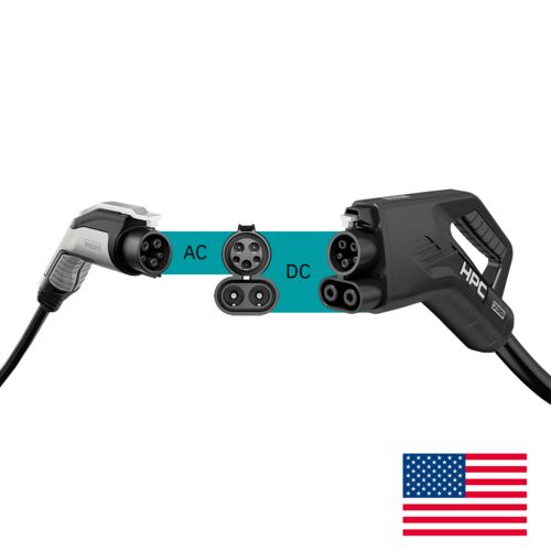
We have developed the Combined Charging System (CCS) together with leading automobile manufacturers. The special feature is the CCS charging inlet in the vehicle, into which both AC and DC charging connectors fit. The electric vehicle thus requires just one charging interface for AC and DC charging.
The mating face structure of the type 1 and type 2 charging standards follow the CCS principle. CCS type 2 was declared the official charging standard for all of Europe by the European Commission back in 2013. In the meantime, our goal of establishing CCS as the global fast charging standard has become a reality in large parts of the world. And more and more countries are adopting CCS.
What are the advantages of CCS in practice?
- Flexible AC and DC charging via just one vehicle charging inlet
- Vehicle manufacturers save on components, space, and costs
- Highest degree of safety thanks to actuator interlocking and temperature monitoring
- High acceptance and prevalence in large parts of the world
Charging connector locking For maximum safety during the charging process
All CCS charging inlets are equipped with an electromagnetic locking actuator in accordance with the standards. This locks the charging connector into place laterally or directly on the locking clip in the mating face during the charging process.
The actuator bolt is designed to withstand high pull-out forces. This makes it impossible to pull the charging connector out during the charging process.
Precise temperature monitoring Reliable protection against overheating
A safe charging process also includes monitoring the temperature in the CCS charging system. According to IEC 62196, heating must not exceed 90°C. Temperature-dependent resistance sensors, e.g., Pt 1000, therefore ensure fast and precise temperature measurement at the DC power contacts.
The temperature values are communicated to the charging controller via corresponding signal outputs. If overheating occurs, e.g., due to excessively high external temperatures or overload, the charging controller can abort the charging process or derate the charging power.
How does a charging station work? What happens during the charging process? What needs to be considered during engineering?
Today’s charging stations and home chargers in part have to satisfy high demands on availability, safety, and convenience. A complex structure made up of a large number of components is not unusual. Our videos clearly explain the structure and interaction of the individual components and demonstrate how to meet all the requirements on a state-of-the-art and networked charging infrastructure.
How is the charging current delivered to the e-vehicle? The Charging functional unit
- Power electronics
- Power contactor
- Fuse
- Cooling unit
- Charging cable
- Infrastructure charging socket
- Vehicle charging inlet
How is the charging process controlled? The functional area “Control and monitor”
- Charging controller
- Energy measurement
- Residual current monitoring
- Insulation monitoring
- Temperature measurement
How do charging stations communicate? The Networking and Communication functional unit
- User authorization via RFID
- LED status indicator
- Touch operation
- Wireless connection via cellular communication
- Wired connection via Ethernet
- Ethernet surge protection
How are expensive failures avoided? The Supply and Protection functional unit
- Power supply
- Surge protection
- Device protection
- Load measurement
- Energy monitoring
How is wiring and installation performed? The Connection functional unit
- Cable entry
- Power connection for feed-in
- Marshalling and potential distribution
- Data connection
- Socket and USB port for maintenance
Glossary Technical terms and abbreviations clearly explained
Each business area develops its own language and terminology, if only to be able to give new technologies a name. You will find an explanation of the terms and abbreviations commonly used in the field of e-mobility here:
Vehicles
- EV: Electric vehicle. Collective term for all vehicles completely or partially powered by electricity.
- BEV: Battery electric vehicle. Vehicle powered purely with electricity whose drive energy is stored in chemical form in batteries.
- HEV: Hybrid electric vehicle. Vehicle that has both an internal combustion engine and a battery electric drive.
- PHEV: Plug-in hybrid electric vehicle. Like HEVs, but the battery can also be charged externally via a charging connector.
Charging connectors and sockets
- Inlet: Charging socket in electric vehicles into which the vehicle charging connector is plugged. Also called a vehicle charging inlet.
- Connector: Charging connector that is plugged into the charging inlet in the electric vehicle. Also called a vehicle charging connector.
- Plug: Charging connector that is plugged into the charging socket on the charging station. Also called an infrastructure charging plug.
- Socket outlet: Charging socket in the charging station to which a vehicle is connected via a mobile AC charging cable and charged in accordance with charging mode 3, case B. Also called an infrastructure charging socket.
Charging types and standards
- AC charging: Charging with single-phase or three-phase alternating current (charging mode 1, 2, or 3).
- DC charging: Charging with direct current (charging mode 4).
- CCS: Combined Charging System: Charging connection system for type 1 and type 2, which allows both AC charging and DC charging with just one vehicle charging inlet.
- Combo: Obsolete designation for CCS.
- Type 1: Charging standard for North America and other regions, described in the SAE J1772 and IEC 62196-3 standards.
- Type 2: Charging standard for Europe and other regions, described in the IEC 62196-3 standard.
- GB/T: National Chinese standards. The GB/T 20234 standard describes the charging standard for China.
- NACS: North American Charging Standard: Alternative charging standard for type 1 for the North American market.
- HPC: High Power Charging, also ultra-fast charging: DC charging with powers upwards of 375 kW. Using liquid cooling, up to 500 kW is currently possible permanently or up to 700 kW for a short time.
- MCS: Megawatt Charging System. Charging standard for the DC charging of utility vehicles with powers of up to 3.75 MW.
- V2G: Vehicle-to-grid. A form of bidirectional charging. The vehicle is charged from the supply network and can also feed energy back into the grid as needed. In accordance with the ISO 15118 standard.
- V2H: Vehicle-to-home. As per V2G, but the vehicle serves as the home battery. The energy fed in is not fed back into the grid; instead, it is used to maximize the autonomy (self-sufficiency) of the home.
Charging infrastructure
- Charging point: Point for connecting and charging a vehicle. A charging station has one or more charging points.
- Charging system: Interaction of all technical components inside a charging station (electromechanics, electronics, software) that are necessary for charging a vehicle.
- Home charger: Wall-mounted charging system in a manufacturer-specific housing. Mostly for private AC charging in the home environment with up to 11 or 22 kW, e.g., in the garage or carport.
- Charging station: Stand-alone charging system in a manufacturer-specific housing. Mostly for public or semi-public AC and/or DC charging including billing system, e.g., at hotels or supermarkets.
- EVSE: Electric vehicle supply equipment: See home charger and charging station.
- Charging park: Network of several public or semi-public charging stations, on highways or in parking garages, for example.
- CPO: Charging point operator: The company or legal entity that operates individual charging points or charging parks and charges vehicle users for the charged energy.
Communication and control
- CP: Control pilot. Signal contact or signal line in a type 1, type 2, and GB/T charging cable. Used to transfer control information between the charging station and the vehicle.
- PP: Proximity pilot. Signal contact or signal line in a type 2 charging cable. Provides the vehicle with information that charging is taking place with a specific charging current so that the immobilizer is activated.
- CC: Connection confirmation. Signal contact or signal line in a GB/T charging cable. Provides the vehicle with information that charging is taking place with a specific charging current to activate the immobilizer.
- CS: Connection switch. Signal contact or signal line in a type 1 charging cable. Notifies the charging station when the locking lever on the charging connector has been operated so that the charging station interrupts the charging current.
- IC-CPD: In-cable control and protection device. A control and protection device integrated into the charging cable. Enables single-phase AC charging in accordance with charging mode 2 at household sockets with powers of up to 3.6 kW.
- Backend: Enables the CPO to operate its charging points on the software side. Includes user management, payment processing (usually via a third-party provider), and technical monitoring of the charging points via the cloud.
- OCPP: Open Charge Point Protocol. Used for communication between the charging station and the backend.
- PnC: Plug-and-charge. Simplifies the charging process by making authentication and billing run automatically in the background. In accordance with the ISO 15118 standard.