PSR-MC43-2SDO-1DO-24DC-SC
-
Safety relay module
1087561
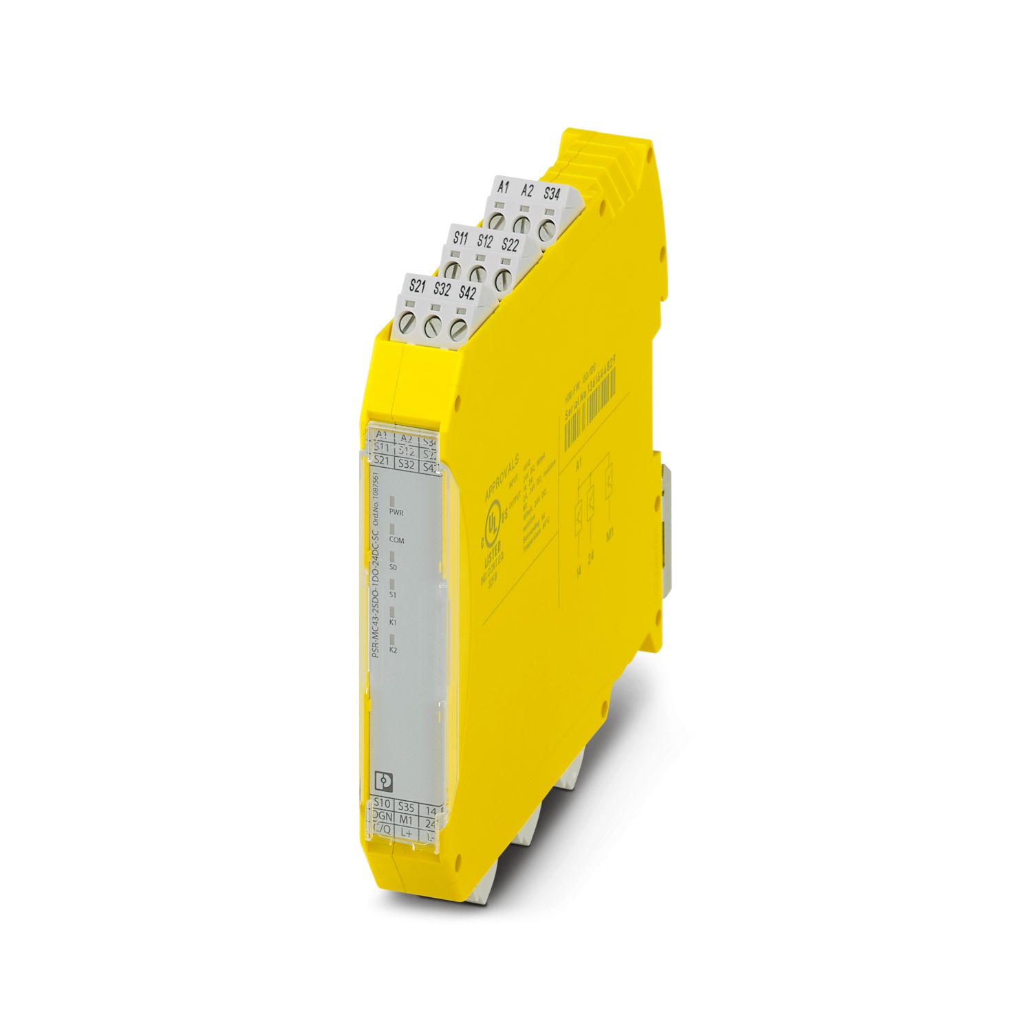
Safety relay module with IO-Link for emergency stop, safety doors, and light grids, to SIL 3, cat. 4, PL e, 2 sensor circuits, automatic or manual, monitored start, 2 safe digital outputs, 1 signal output, US = 24 V DC, pluggable screw terminal block
Free download available.
Downloads
Product details
| Note on application | |
| Note on application | Only for industrial use |
| Product type | Safety relays |
| Product family | PSRmini |
| Application | Emergency stop |
| Safety door | |
| Light grid | |
| Transponder | |
| Switching capacities | |
| Safety shut-off mats | |
| Control | 1 and 2 channel |
| Insulation characteristics: Air clearances and creepage distances between the power circuits | |
| Overvoltage category | II |
| Degree of pollution | 2 |
| Times | |
| Typical response time | < 200 ms (automatic start) |
| < 175 ms (manual, monitored start) | |
| Typ. starting time with Us | < 200 ms (when controlled via A1) |
| Response time | < 10 ms |
| Restart time | < 1 s (Boot time) |
| Recovery time | 250 ms (following demand of the safety function) |
| Maximum power dissipation for nominal condition | 4 W (UB = UBL = 30 V, IL1 = IL2 = 2.4 A) |
| Nominal operating mode | 100% operating factor |
| Air clearances and creepage distances between the power circuits | |
| Rated insulation voltage | 63 V |
| Rated surge voltage/insulation | Safe isolation, 0.5 kw between logic and IO-Link |
| Basic insulation 4 kV between all current paths and housing | |
| Supply | |
| Designation | L+/L- |
| Nominal voltage for I/O supply | 24 V DC -20 % / +25 % (Provided via the IO-Link interface of the IO-Link master.) |
| Current consumption | typ. 8 mA |
| Protective circuit | Serial protection against polarity reversal; Suppressor diode |
| Supply | |
| Designation | A1/A2 |
| Rated control circuit supply voltage US | 19.2 V DC ... 30 V DC |
| Rated control circuit supply voltage US | 24 V DC -20 % / +25 % (provide external protection) |
| Rated control supply current IS | typ. 72 mA |
| Power consumption at US | typ. 1.73 W |
| Inrush current | typ. 12 A (Δt < 10 µs) |
| Filter time | 1 ms (For the logic. At A1 in the event of voltage dips at Us ) |
| Protective circuit | Parallel protection against polarity reversal; Suppressor diode (Provide external fuse protection, see safety notes. Fuse type: 5 AT) |
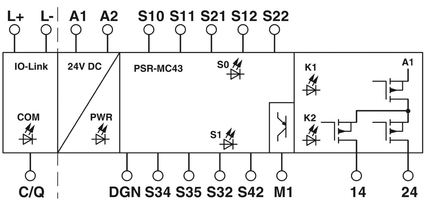
| Digital: Sensor circuit S0 (S10, S12, S22) | |
| Description of the input | safety-related sensor inputs |
| IEC 61131-2 type 3 (S10, S12) PNP (S22) | |
| Number of inputs | 3 |
| Input voltage range "0" signal | 0 V DC ... 5 V DC (S10, S12) |
| For S22, see note in “Signal generator connection versions” section. | |
| Input voltage range "1" signal | 11 V DC ... 30 V DC (S10, S12) |
| 0 V (S22) | |
| Input current range "0" signal | 0 mA ... 2 mA (S10, S12) |
| Inrush current | < 5 mA (typ. with US at S10) |
| < 5 mA (typ. with US at S12) | |
| > -7 mA (typ. with US at S22) | |
| Filter time | max. 1.5 ms (Test pulse width, low test pulses (S10, S12) ) |
| Test pulse rate = 5 x Test pulse width | |
| Deactivate the switch-on pulses for safety applications. | |
| Concurrence | ∞ |
| Max. permissible overall conductor resistance | 150 Ω |
| Protective circuit | Suppressor diode |
| Current consumption | < 5 mA (typ. with US at S10) |
| < 5 mA (typ. with US at S12) | |
| > -7 mA (typ. with US at S22) | |
| Digital: Sensor circuit S1 (S32, S42) | |
| Description of the input | safety-related sensor inputs |
| IEC 61131-2 type 3 | |
| Number of inputs | 2 |
| Input voltage range "0" signal | 0 V DC ... 5 V DC |
| Input voltage range "1" signal | 11 V DC ... 30 V DC |
| Input current range "0" signal | 0 mA ... 2 mA |
| Inrush current | < 10 mA (typ. with US, Δt = 500 µs) |
| Filter time | max. 1.5 ms (Test pulse width of low test pulses) |
| Test pulse rate = 5 x Test pulse width | |
| Deactivate the switch-on pulses for safety applications. | |
| Concurrence | ∞ |
| Max. permissible overall conductor resistance | 150 Ω |
| Protective circuit | Suppressor diode |
| Current consumption | < 5 mA (typ. with US) |
| Digital: Diagnostic input (DGN) | |
| Description of the input | non-safety-related |
| Potential A1/A2 or US | |
| Number of inputs | 1 |
| Input voltage range | 0 V DC ... 30 V DC |
| Protective circuit | Suppressor diode |
| Current consumption | typ. 30 mA |
| Digital: Start circuit (S34, S35) | |
| Number of inputs | 2 |
| Input voltage range "1" signal | 19.2 V DC ... 30 V DC |
| Inrush current | < 10 mA (typ. with US, Δt = 100 ms) |
| Max. permissible overall conductor resistance | 150 Ω |
| Protective circuit | Suppressor diode |
| Current consumption | < 7 mA (typ. with US at S34) |
| < 5 mA (typ. with US at S35) | |
| IO-Link | |
| Designation | IO-Link |
| Transmission speed | 230 kbps (COM3) |
| Cycle Time | 5 ms |
| Process data update | 5 ms |
| Amount of process data | max. 31 Byte (Input data) |
| max. 16 Byte (Output data) | |
| Description of the input | IO-Link switching and communication cable |
| Number of inputs | 1 |
| Connection method | Screw connection |
| Connection technology | 3-conductor |
| Number of ports | 1 |
| Port type | Class A |
| Digital: 14, 24 | |
| Output description | Safety-related digital outputs |
| PNP, IEC 61131-2 Type 2 | |
| Number of outputs | 2 |
| Protective circuit | Freewheeling circuit for inductive loads |
| Short-circuit protection | Yes |
| Output voltage | ≥ 23 V DC (Us - 1 V) |
| Leakage current | max. 1 mA (in the safe state) |
| Ohmic load | min. 12 Ω |
| Max. capacitive load | max. 10 µF (2.4 A load) |
| max. 4.7 µF (1 A load) | |
| Max. inductive load | max. 1 H |
| Limitation of the voltage induced on circuit interruption | max. 50 V |
| Output current | max. 2.4 A |
| Inrush current | max. 4.8 A (Δt = 10 ms) |
| Min. load current | 2 mA |
| Switching frequency | 1 Hz (Resistive, inductive, capacitive) |
| Output voltage when switched off | < 5 V DC (in the safe state) |
| Discharging circuit | No |
| Signal: M1 | |
| Output description | PNP |
| non-safety-related | |
| Number of outputs | 1 |
| Voltage | approx. 22 V DC (Us - 2 V) |
| Current | max. 100 mA |
| Maximum inrush current | 500 mA (Δt = 1 ms at Us) |
| Switching frequency | 1 Hz (Resistive, inductive, capacitive) |
| Protective circuit | Suppressor diode |
| Connection technology | |
| pluggable | yes |
| Conductor connection | |
| Connection method | Screw connection |
| Conductor cross-section rigid | 0.2 mm² ... 2.5 mm² |
| Conductor cross-section flexible | 0.2 mm² ... 2.5 mm² |
| Conductor cross-section AWG | 24 ... 12 |
| Stripping length | 7 mm |
| Screw thread | M3 |
| Tightening torque | 0.5 Nm ... 0.6 Nm |
| Status display | 5 x LED (green) |
| Operating voltage display | 1 x LED (green, yellow, red) |
| Width | 17.5 mm |
| Height | 112.2 mm |
| Depth | 114.5 mm |
| Color (Housing) | yellow (RAL 1018) |
| Housing material | PBT |
| Safety data | |
| Stop category (EN 60204-1) | 0 |
| Safety data: EN ISO 13849 | |
| Performance level (PL) | e |
| Safety data: IEC 61508 - High demand | |
| Safety Integrity Level (SIL) | 3 |
| Safety data: EN IEC 62061 | |
| Safety Integrity Level (SIL) | 3 |
| Ambient conditions | |
| Degree of protection | IP20 |
| Min. degree of protection of inst. location | IP54 |
| Ambient temperature (operation) | -40 °C ... 60 °C (observe derating) |
| Ambient temperature (storage/transport) | -40 °C ... 85 °C |
| Maximum altitude | ≤ 2000 m (Above sea level) |
| Max. permissible humidity (storage/transport) | 75 % (on average, 85% infrequently, non-condensing) |
| Max. permissible relative humidity (operation) | 75 % (on average, 85% infrequently, non-condensing) |
| Shock | 30g |
| Vibration (operation) | 10 Hz ... 150 Hz, 5g |
| CE | |
| Identification | CE-compliant |
| Air clearances and creepage distances between the power circuits | |
| Standards/regulations | EN 60947-5-1 |
| Mounting type | DIN rail mounting |
| Assembly note | See derating curve |
| Mounting position | vertical or horizontal |
| Item number | 1087561 |
| Packing unit | 1 pc |
| Minimum order quantity | 1 pc |
| Sales key | DNA |
| Product key | DNA181 |
| GTIN | 4055626885803 |
| Weight per piece (including packing) | 164 g |
| Weight per piece (excluding packing) | 132.38 g |
| Customs tariff number | 85371098 |
| Country of origin | DE |
ECLASS
| ECLASS-13.0 | 27371819 |
ETIM
| ETIM 9.0 | EC001449 |
UNSPSC
| UNSPSC 21.0 | 39122200 |
| China RoHS | |
| Environment friendly use period (EFUP) |
EFUP-50
An article-related China RoHS declaration table can be found in the download area for the respective article under "Manufacturer declaration". For all articles with EFUP-E, no China RoHS declaration table issued and required.
|
| EU REACH SVHC | |
| REACH candidate substance (CAS No.) | No substance above 0.1 wt% |
Compatible products
-
-
PSR-CT-M-SEN-1-8 - Safety switch sensor 2702975
-
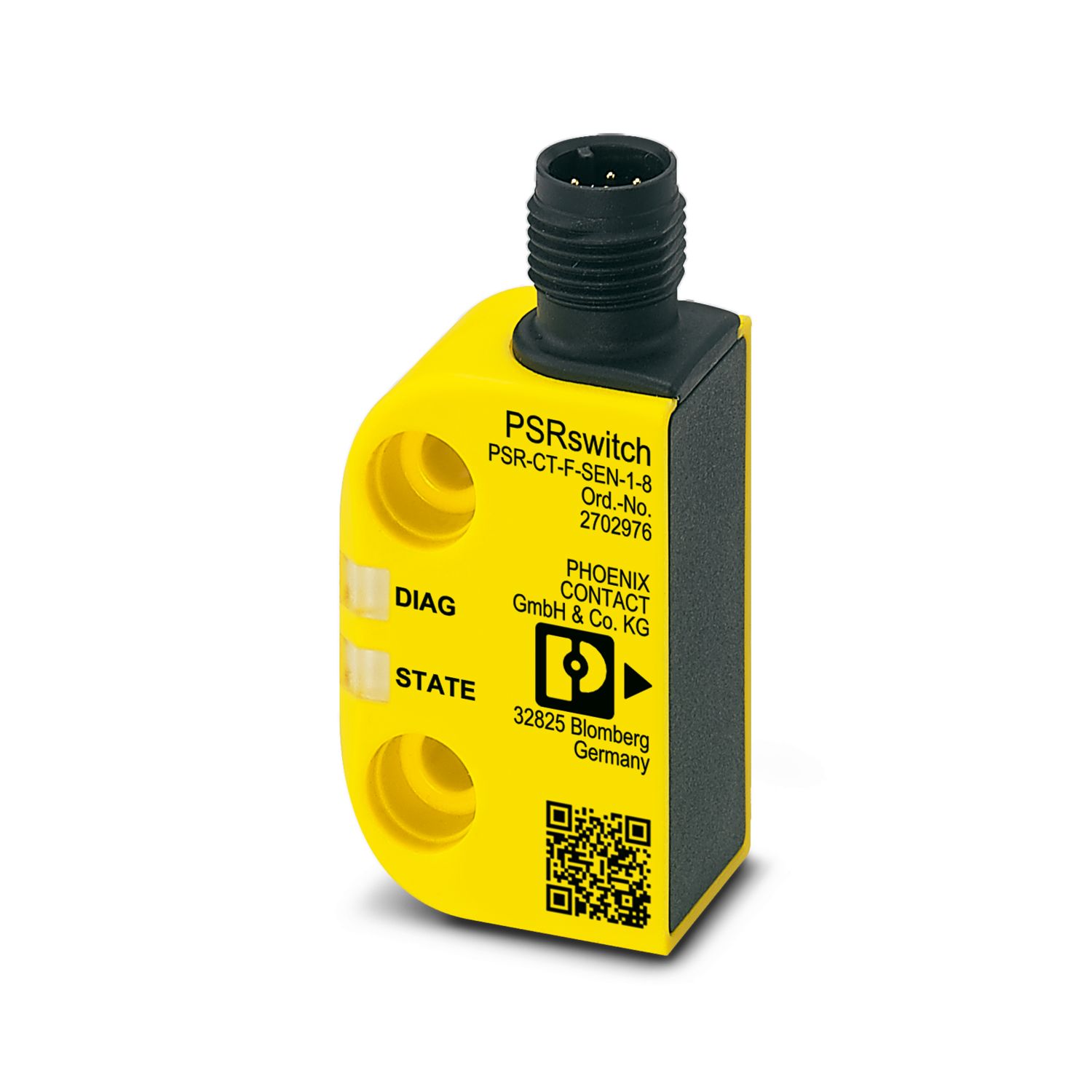
PSR-CT-F-SEN-1-8 - Safety switch sensor 2702976
-
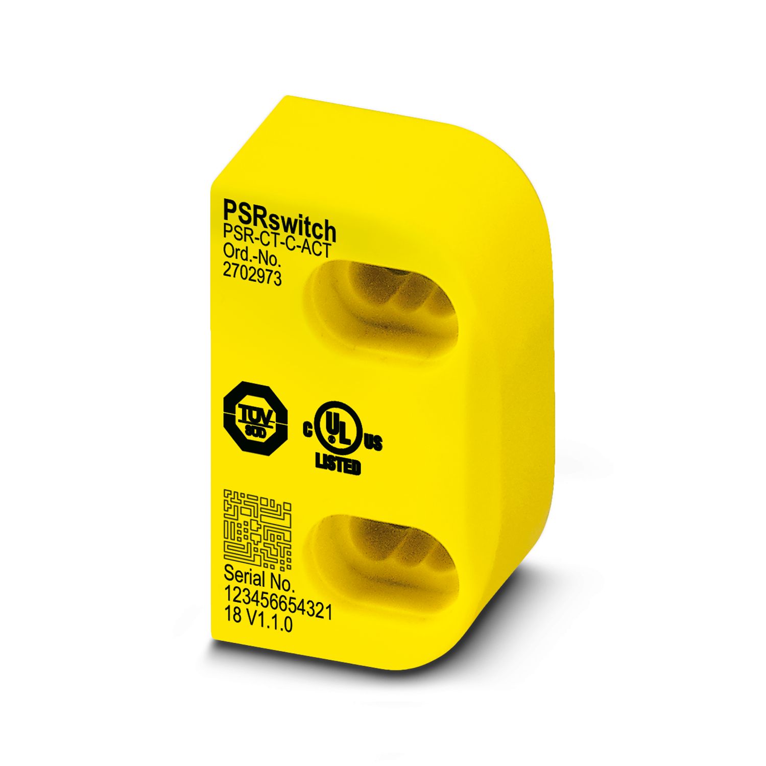
PSR-CT-C-ACT - Safety switch actuator 2702973
-
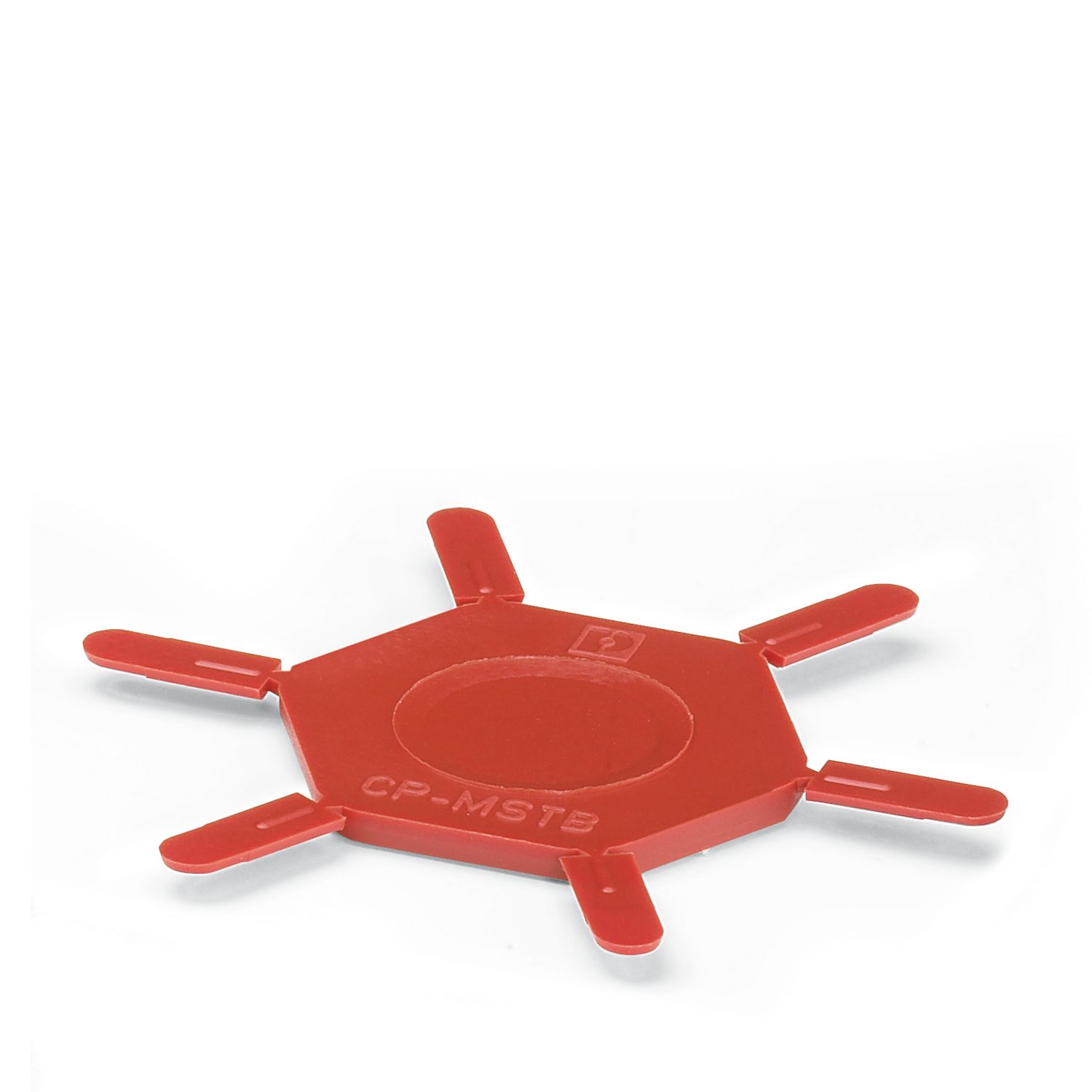
CP-MSTB - Coding profile 1734634
-
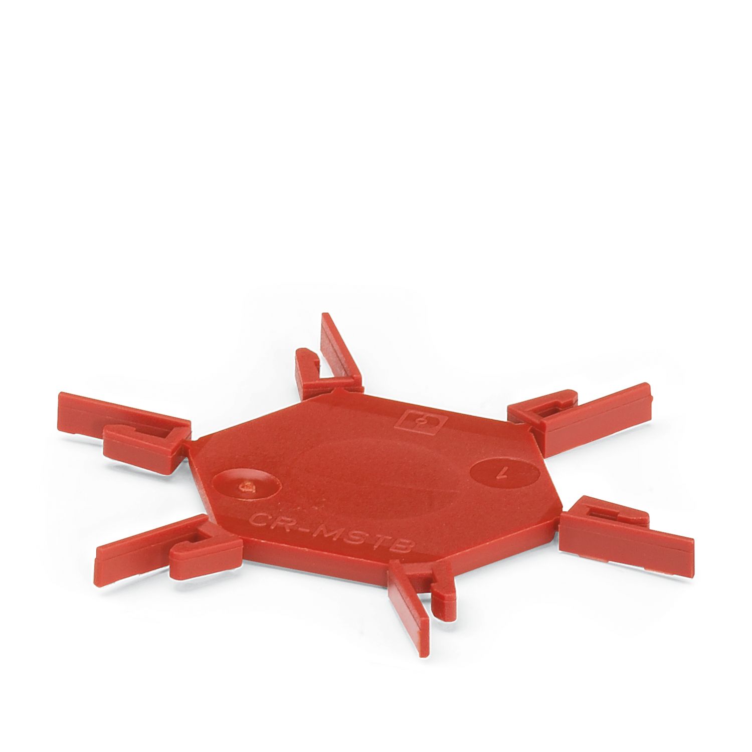
CR-MSTB - Coding section 1734401
-
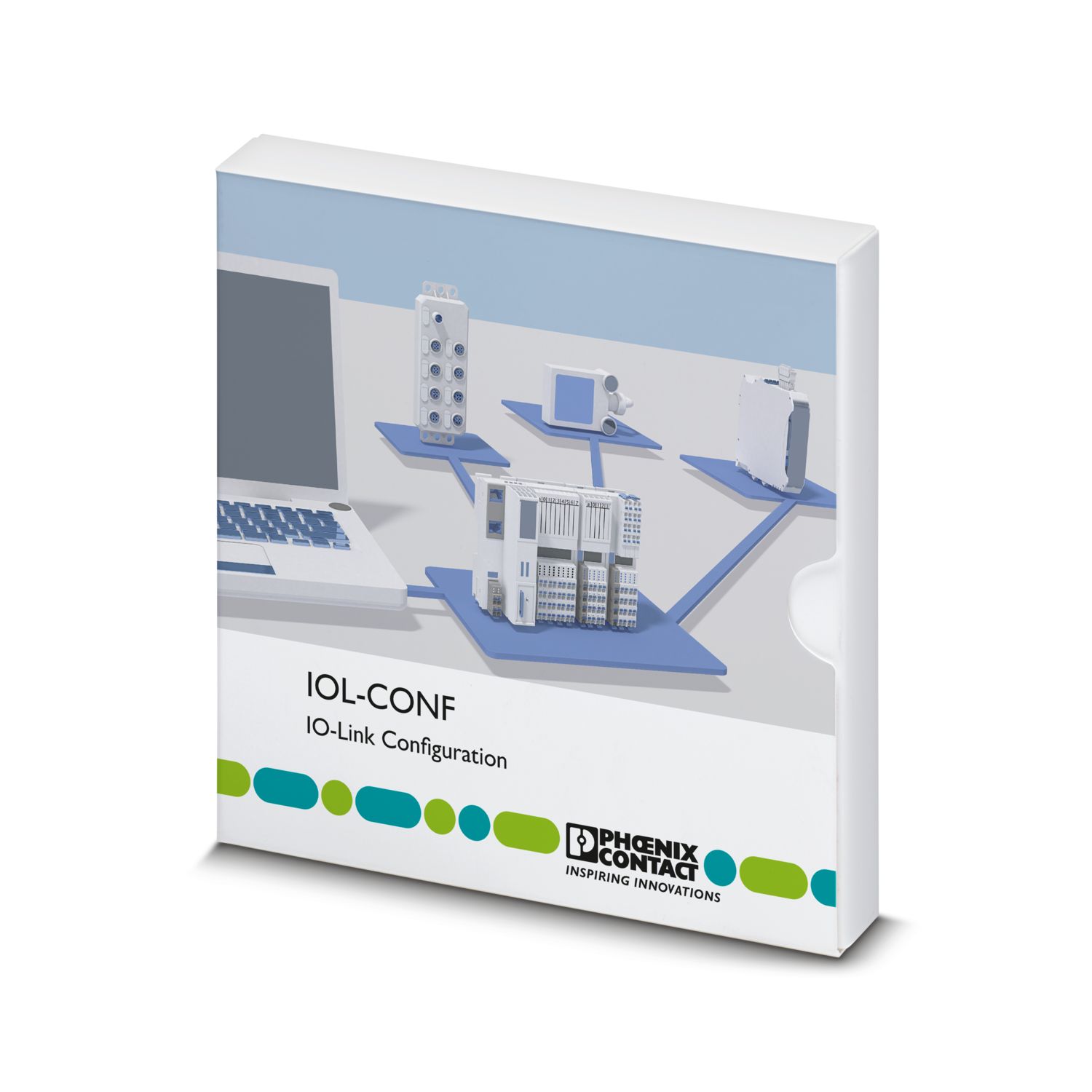
IOL-CONF - Configuration and diagnostic software 1083065
-
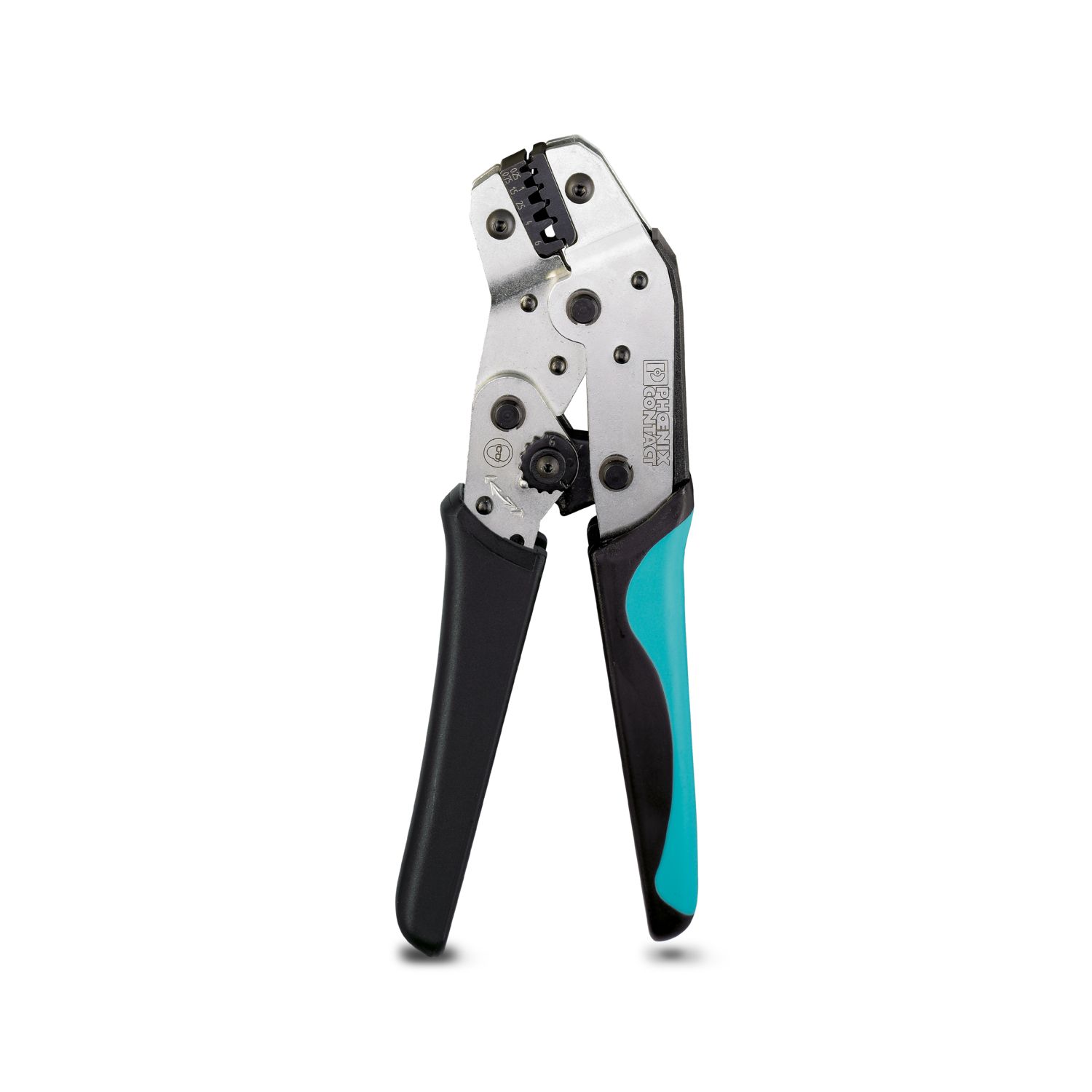
CRIMPFOX 6 - Crimping pliers 1212034
Your advantages
Up to Cat. 4/PL e in accordance with ISO 13849-1, SIL 3 in accordance with EN IEC 62061, SIL 3 in accordance with IEC 61508
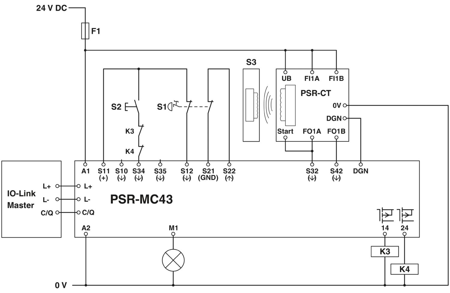
For emergency stop and safety door monitoring, plus evaluation of light grids
For monitoring 4-wire control strips or safety shut-off mats in accordance with EN ISO 13856-1
2 sensor circuits
2 safe digital outputs
1 digital signal output
Diagnostic data via IO-Link in combination with PSR-CT safety switches
1- and 2-channel control
Manually monitored and automatic activation
PHOENIX CONTACT Trading LLC
Twin Tower Building No. 3279, 6th Floor, King Abdullah Branch Road, Al Quds District, Riyadh 13214, Kingdom of Saudi Arabia, Short Address Code: RFQA3279