
The bus coupler with integrated I/Os is intended for use within a Modbus RTU/ASCII network and represents the link to the Inline I/O system. Up to 61 Inline devices can be connected to the bus coupler. The bus coupler supports a maximum of 8 PCP devices.
IL MOD BK DI8 DO4-PAC
-
Bus coupler
2878696
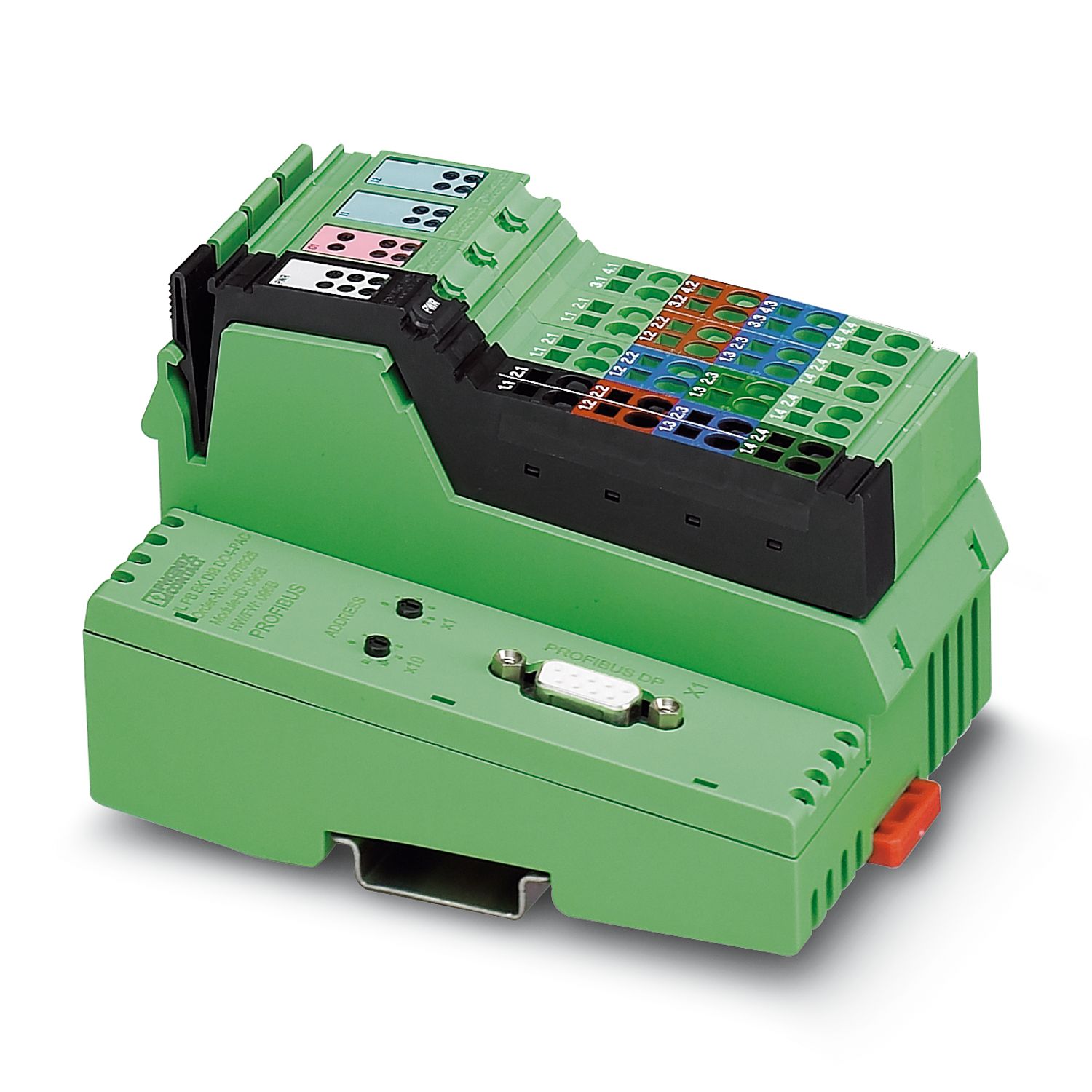
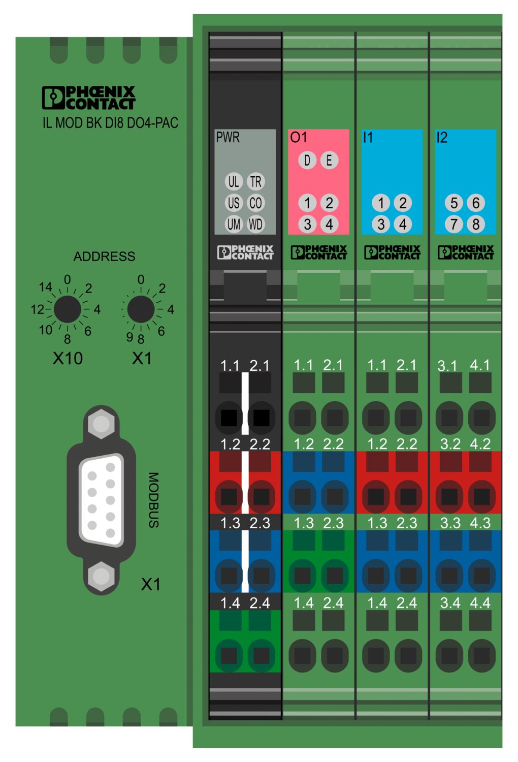
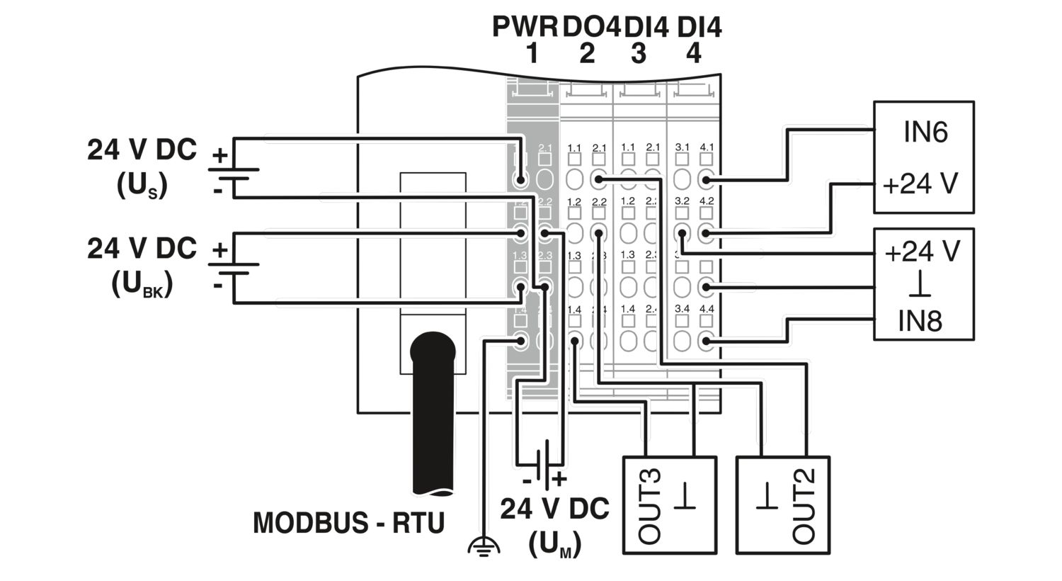

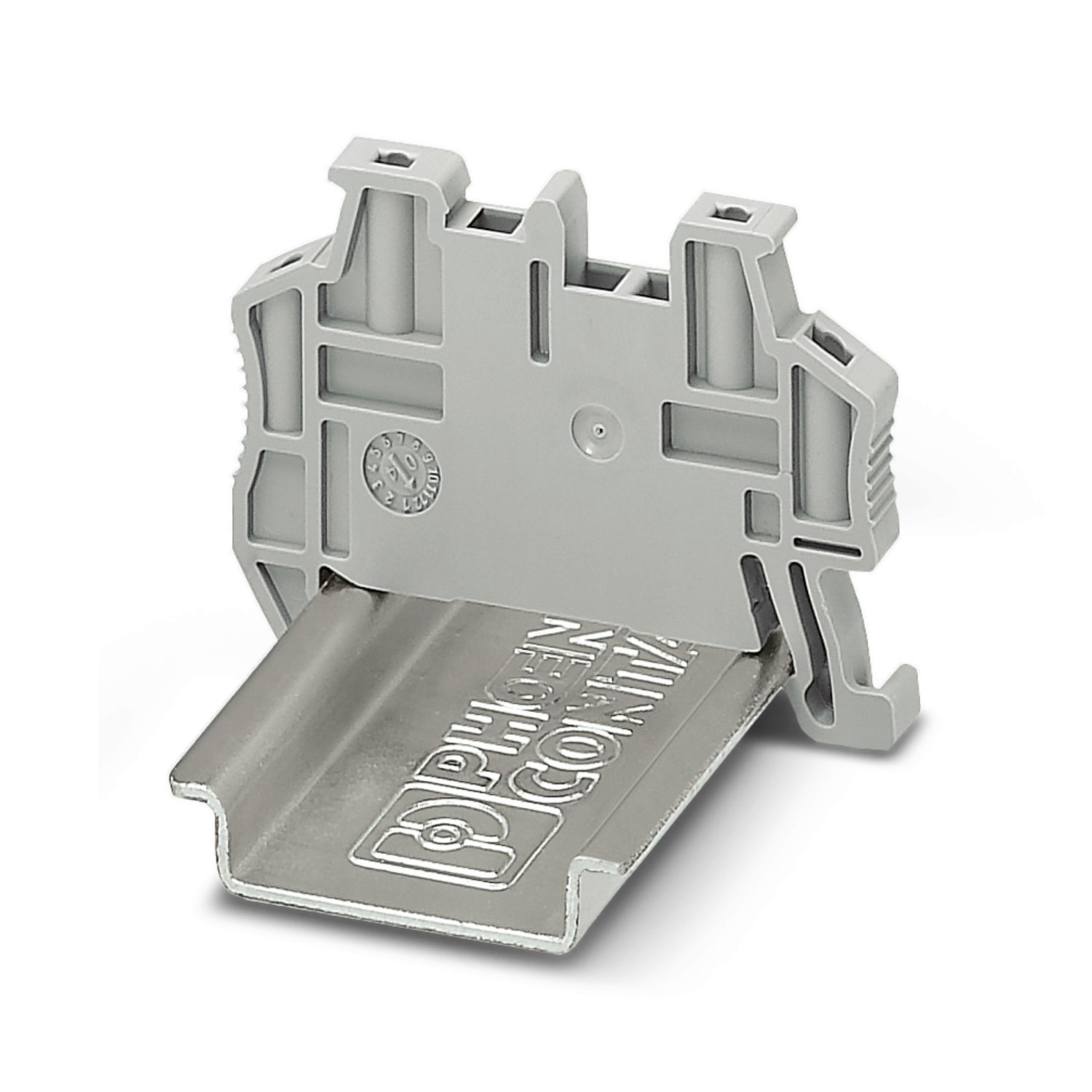
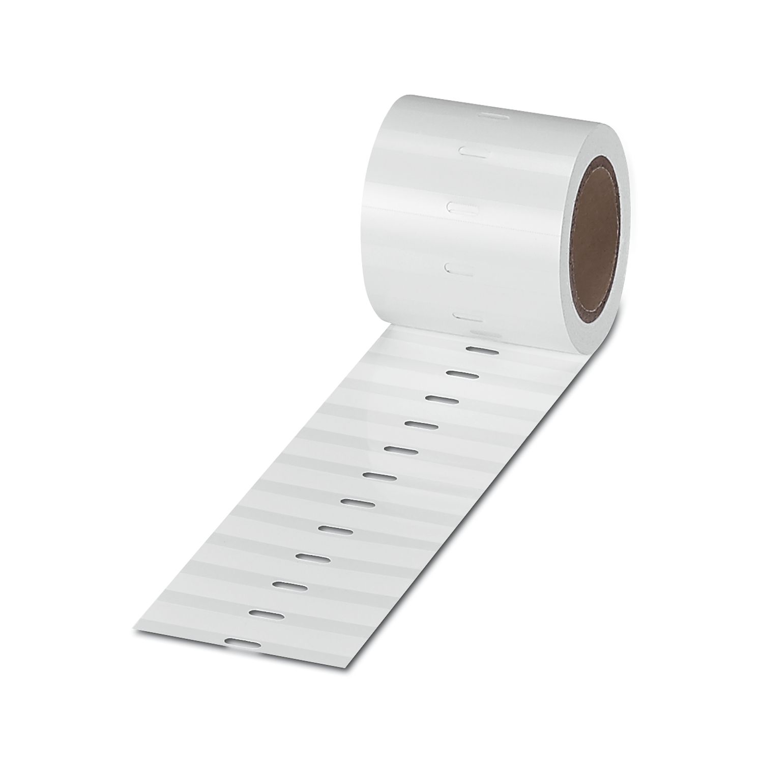
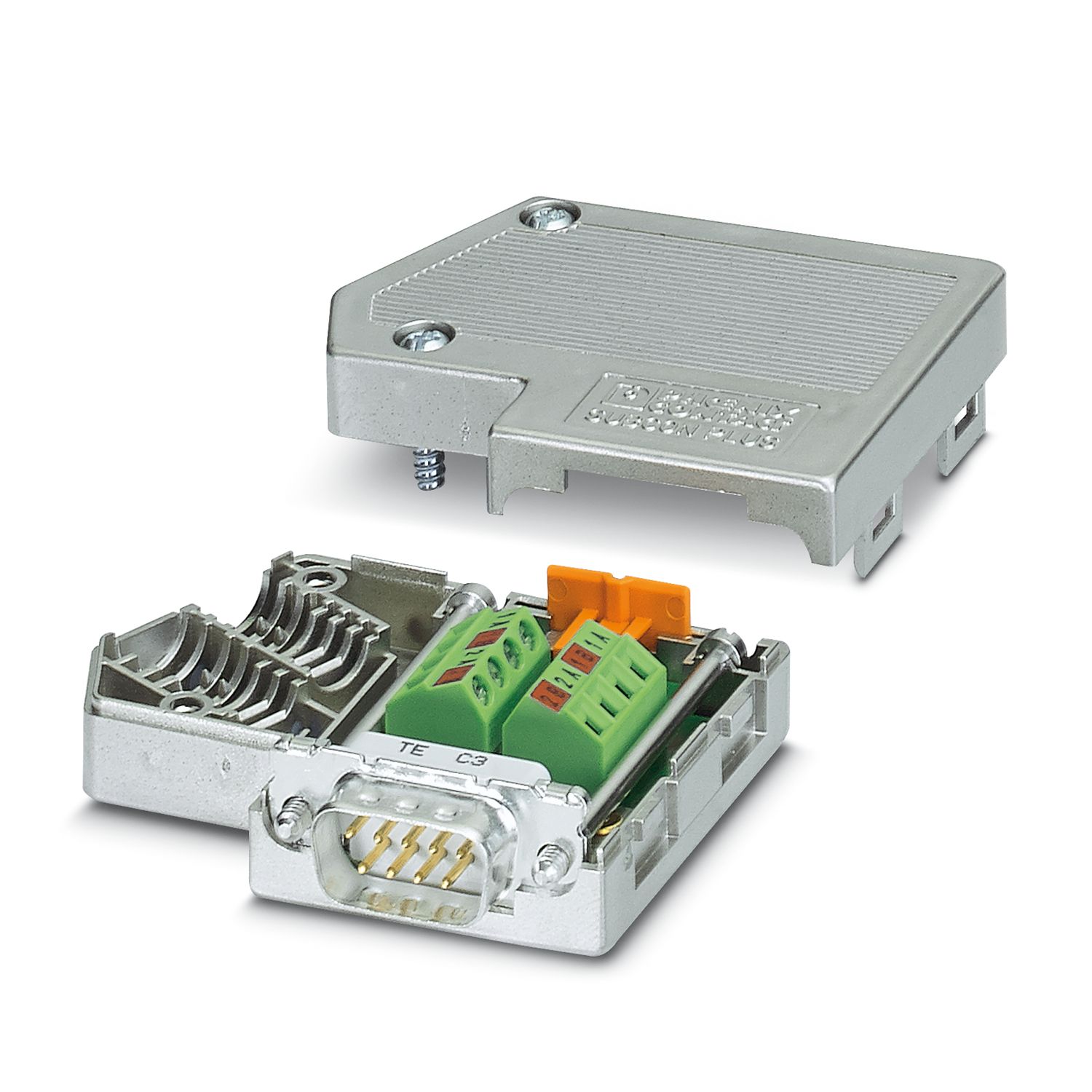
Inline, Bus coupler, Modbus/RTU, D-SUB-9 female connector, Digital inputs: 8, 24 V DC, connection technology: 3-conductor, Digital outputs: 4, 24 V DC, 500 mA, connection technology: 3-conductor, transmission speed in the local bus: 500 kbps / 2 Mbps, degree of protection: IP20, including inline connectors, marking fields, and end plate; The product is being prepared for compliance with the Cyber Resilience Act (CRA).
Free download available.
Downloads
Product details
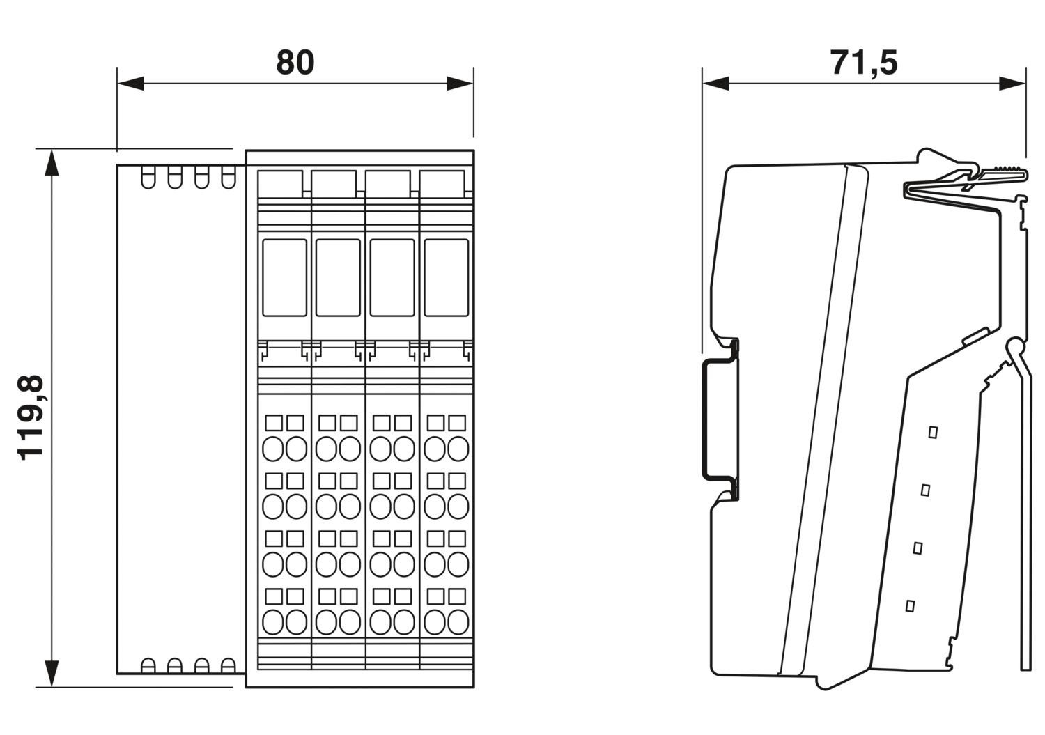
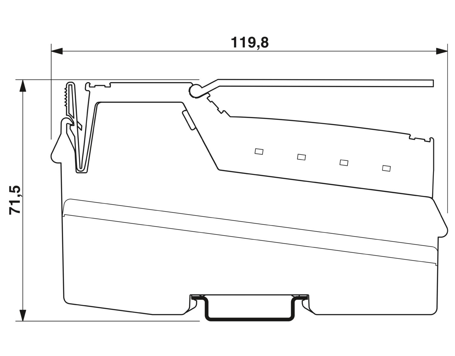
| Dimensional drawing |
|
| Width | 80 mm |
| Height | 119.8 mm |
| Depth | 71.5 mm |
| Note on dimensions | Specfications with connectors |
| Note on application | Only for industrial use |
| Note on application | As things stand now, we are preparing the product so that, as of December 11, 2027, it will comply with the requirements of the EU Cyber Resilience Act (CRA) based on the information currently available regarding the CRA. |
| Utilization restriction | |
| CCCex note | Use in potentially explosive areas is not permitted in China. |
| Mounting type | DIN rail mounting |
| Color (Housing) | green (RAL 6021) |
| Modbus/RTU | |
| Number of interfaces | 1 |
| Connection method | D-SUB-9 female connector |
| Note on the connection method | Electrically isolated supply, shielding directly connected to functional ground |
| Transmission speed | 1.2 kBit/s ... 115.2 kBit/s (can be parameterized) |
| Inline local bus | |
| Number of interfaces | 1 |
| Connection method | Inline data jumper |
| Transmission speed | 500 kbps / 2 Mbps (automatic detection, no combined system) |
| System limits | |
| Number of supported devices | max. 63 (per station) |
| Number of local bus devices that can be connected | max. 61 (The on-board I/Os are two devices) |
| Number of devices with parameter channel | max. 8 |
| Number of supported branch terminals with remote bus branch | 0 |
| Programming data | |
| Input address area | 8 bit |
| Output address area | 4 bit |
| Register length (bus) | 16 bit |
| Register length (master) | 512 Byte |
| Digital: | |
| Input name | Digital inputs |
| Description of the input | EN 61131-2 type 1 |
| Number of inputs | 8 |
| Connection method | Inline connector |
| Connection technology | 3-conductor |
| Input voltage | 24 V DC |
| Input voltage range "0" signal | -30 V DC ... 5 V DC |
| Input voltage range "1" signal | 15 V DC ... 30 V DC |
| Nominal input voltage UIN | 24 V DC |
| Nominal input current at UIN | typ. 3 mA |
| Current flow | Limited to 3 mA, maximum |
| Permissible conductor length to the sensor | 100 m |
| Typical input current per channel | typ. 3 mA |
| Typical response time | approx. 500 µs |
| Delay at signal change from 0 to 1 | 1.2 ms |
| Delay at signal change from 1 to 0 | 1.2 ms |
| Digital: | |
| Output name | Digital outputs |
| Connection method | Inline connector |
| Connection technology | 3-conductor |
| Number of outputs | 4 |
| Protective circuit | Short-circuit and overload protection; Freewheeling circuit in the output driver |
| Output voltage | 24 V DC -1 V (At nominal current) |
| Limitation of the voltage induced on circuit interruption | approx. -30 V |
| Max. current carrying capacity per output | max. 500 mA |
| Maximum output current per module | max. 2 A |
| Nominal output voltage | 24 V DC |
| Output current when switched off | max. 10 µA (When not loaded, a voltage can be measured even at an output that is not set.) |
| Nominal load, inductive | 12 VA (1.2 H, 48 Ω) |
| Nominal load, lamp | 12 W |
| Nominal load, ohmic | 12 W |
| Maximum operating frequency with inductive nominal load | 0.5 Hz (1.2 H, 48 Ω) |
| Behavior with overload | Auto restart |
| Behavior with inductive overload | Output can be destroyed |
| Behavior at voltage switch-off | The output follows the power supply without delay |
| Reverse voltage resistance to short pulses | Reverse voltage proof |
| Resistance to permanent reverse voltage | max. 2 A |
| Signal delay | typ. 1.2 ms |
| Overcurrent shut-down | min. 0.7 A |
| Product type | I/O component |
| Product family | Inline |
| Type | modular |
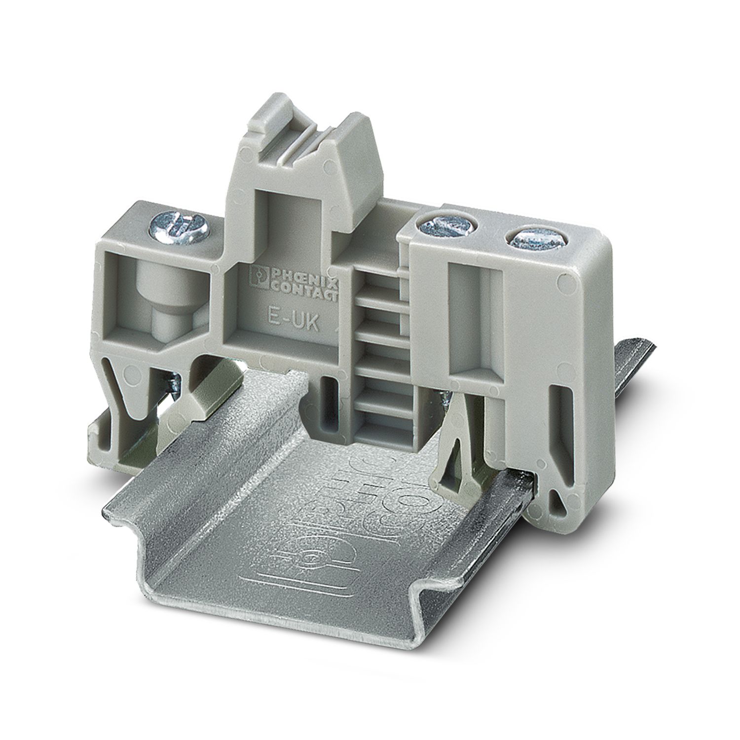
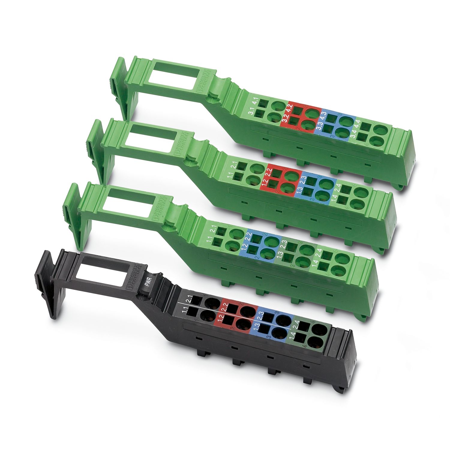
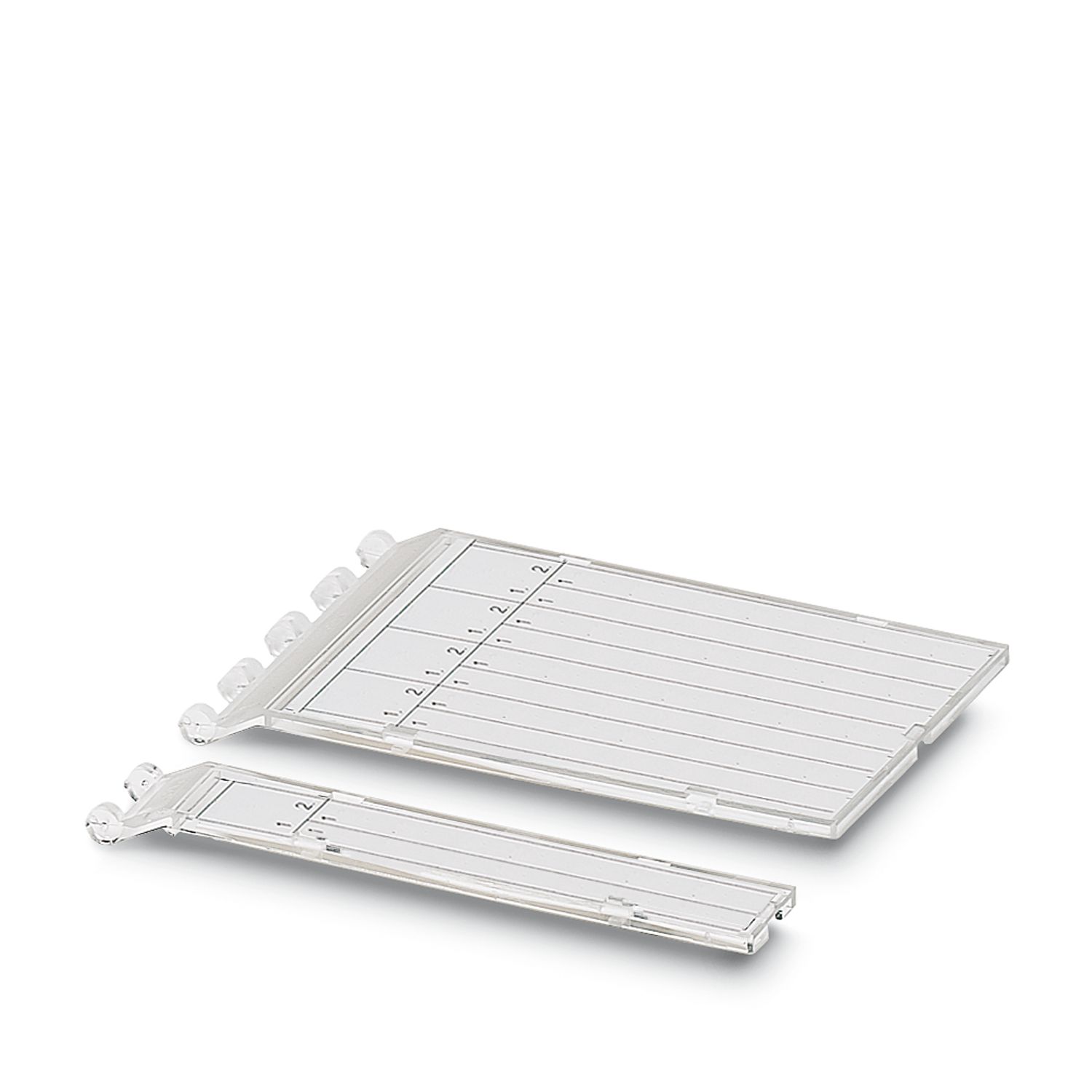
| Scope of supply | including inline connectors, marking fields, and end plate |
| No. of channels | 12 |
| Special properties | The product is being prepared for compliance with the Cyber Resilience Act (CRA) |
| Diagnostics messages | Short-circuit or overload of the digital outputs yes |
| Sensor supply failure yes | |
| Failure of the actuator supply yes | |
| Insulation characteristics | |
| Overvoltage category | II (IEC 60664-1, EN 60664-1) |
| Pollution degree | 2 (IEC 60664-1, EN 60664-1) |
| Maximum power dissipation for nominal condition | 5.3 W |
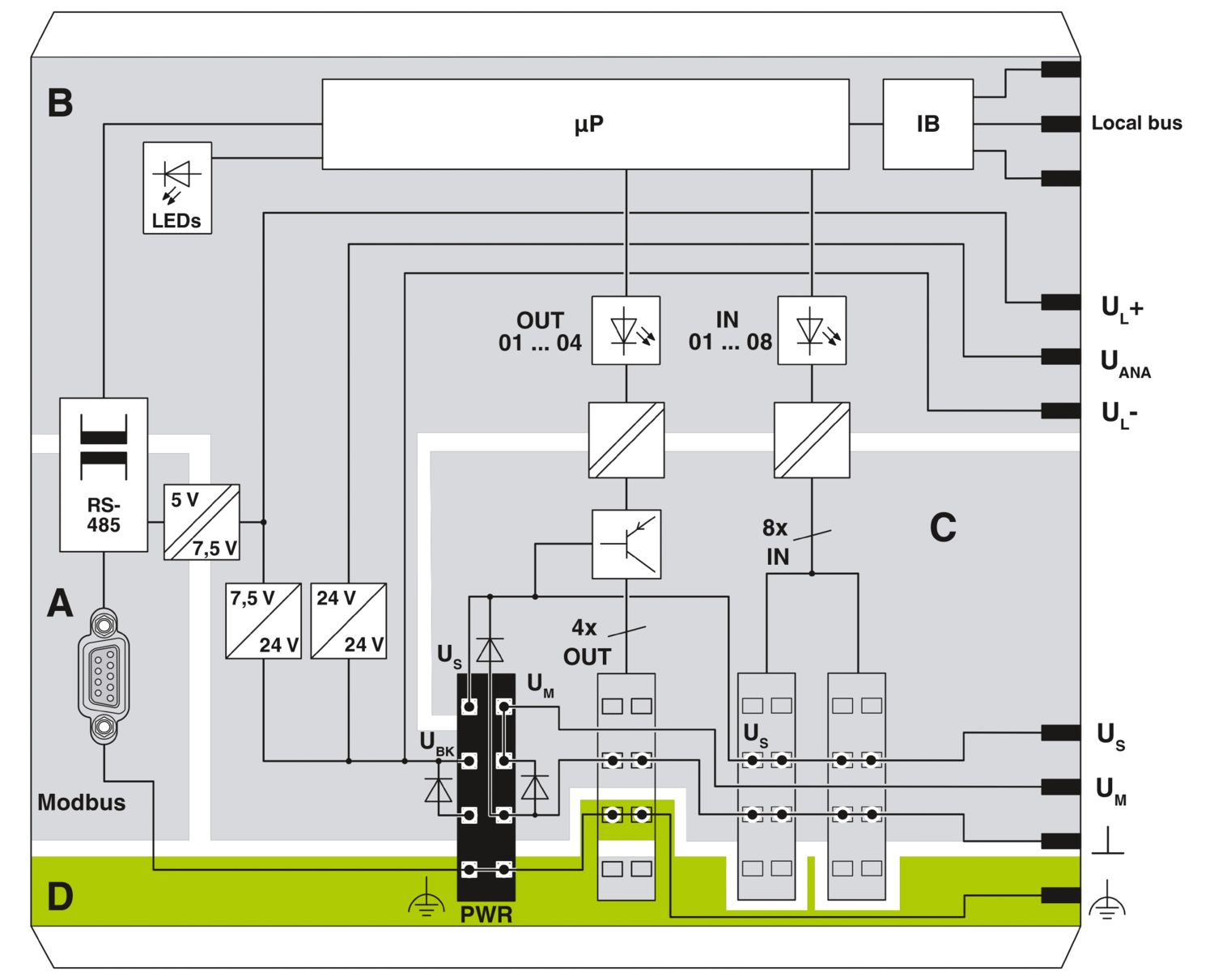
| Potentials: Bus coupler supply UBK; Communications power UL (7.5 V) and the analog supply UANA (24 V) are generated from the bus coupler supply. | |
| Supply voltage | 24 V DC (via Inline connector) |
| Supply voltage range | 19.2 V DC ... 30 V DC (including all tolerances, including ripple) |
| Current draw | max. 0.94 A (with max. number of connected I/O terminal blocks) |
| typ. 40 mA (without connected I/O terminal blocks) | |
| Potentials: Communications power (UL) | |
| Supply voltage | 7.5 V DC |
| Power supply | max. 0.8 A DC |
| Potentials: Supply of analog modules (UANA) | |
| Supply voltage | 24 V DC |
| Supply voltage range | 19.2 V DC ... 30 V DC (including all tolerances, including ripple) |
| Power supply | max. 0.5 A DC |
| Potentials: Main circuit supply (UM) | |
| Supply voltage | 24 V DC (via Inline connector) |
| Supply voltage range | 19.2 V DC ... 30 V DC (including all tolerances, including ripple) |
| Power supply | max. 8 A DC (sum of UM + US) |
| Current draw | max. 8 A DC |
| min. 3 mA (without connected peripherals) | |
| Potentials: Segment circuit supply (US) | |
| Supply voltage | 24 V DC (via Inline connector) |
| Supply voltage range | 19.2 V DC ... 30 V DC (including all tolerances, including ripple) |
| Power supply | max. 8 A DC (sum of UM + US) |
| Current draw | max. 8 A DC |
| min. 3 mA (without connected peripherals) | |
| Electrical isolation/isolation of the voltage ranges | |
| Test voltage: Modbus interface 1 / Modbus interface 2 | 500 V AC, 50 Hz, 1 min |
| Test voltage: Modbus interface 1 / communications power (UBK, UL, UANA) | 500 V AC, 50 Hz, 1 min |
| Test voltage: Modbus interface 1 / I/O (UM, US) | 500 V AC, 50 Hz, 1 min |
| Test voltage: Modbus interface 1 / functional ground | 500 V AC, 50 Hz, 1 min |
| Test voltage: Modbus interface 2 / communications power (UBK, UL, UANA) | 500 V AC, 50 Hz, 1 min |
| Test voltage: Modbus interface 2 / I/O (UM, US) | 500 V AC, 50 Hz, 1 min |
| Test voltage: Modbus interface 2 / functional ground | 500 V AC, 50 Hz, 1 min |
| Test voltage: Communications power (UBK, UL, UANA) / I/O (UM, US) | 500 V AC, 50 Hz, 1 min |
| Test voltage: Communications power (UBK, UL, UANA) / functional ground | 500 V AC, 50 Hz, 1 min |
| Test voltage: I/O (UM, US) / functional ground | 500 V AC, 50 Hz, 1 min |
| Connection technology | |
| Connection name | Inline connector |
| Inline connector | |
| Connection method | Spring-cage connection |
| Conductor cross-section, rigid | 0.08 mm² ... 1.5 mm² |
| Conductor cross-section, flexible | 0.08 mm² ... 1.5 mm² |
| Conductor cross-section AWG | 28 ... 16 |
| Stripping length | 8 mm |
| Ambient conditions | |
| Ambient temperature (operation) | -25 °C ... 60 °C |
| Degree of protection | IP20 |
| Air pressure (operation) | 70 kPa ... 106 kPa (up to 3000 m above sea level) |
| Air pressure (storage/transport) | 70 kPa ... 106 kPa (up to 3000 m above sea level) |
| Ambient temperature (storage/transport) | -40 °C ... 85 °C |
| Permissible humidity (operation) | 10 % ... 95 % (non-condensing) |
| Permissible humidity (storage/transport) | 10 % ... 95 % (non-condensing) |
| Mechanical test | |
| Vibration resistance in accordance with EN 60068-2-6/IEC 60068-2-6 | 5g |
| Shock in accordance with EN 60068-2-27/IEC 60068-2-27 | 25g |
| Protection class | III (IEC 61140, EN 61140, VDE 0140-1) |
BV
Approval ID: 21595/C1 BVABS
Approval ID: 22-2226444-PDAcULus Recognized
Approval ID: E140324LR
Approval ID: LR23398855TA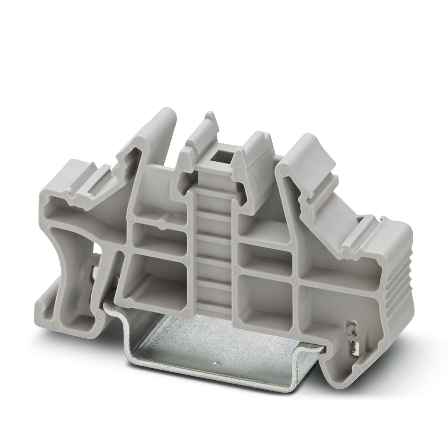
Your advantages
Modbus connection via 9-pos. D-SUB socket
Electrical isolation between Modbus interface and logic
8 digital inputs, 4 digital outputs (on-board)
Data transmission speed in Modbus of 1.2 kbps to 115.2 kbps (configurable)
Rotary coding switches for setting the Modbus address and for configuration
Supported Modbus addresses from 1 to 99
Automatic detection of the transmission speed in the local bus (500 kbps or 2 Mbps)
Shipbuilding and UL approvals