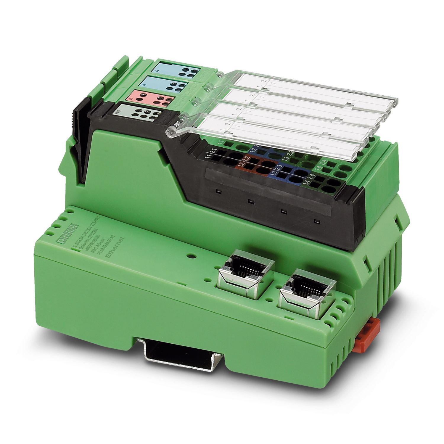
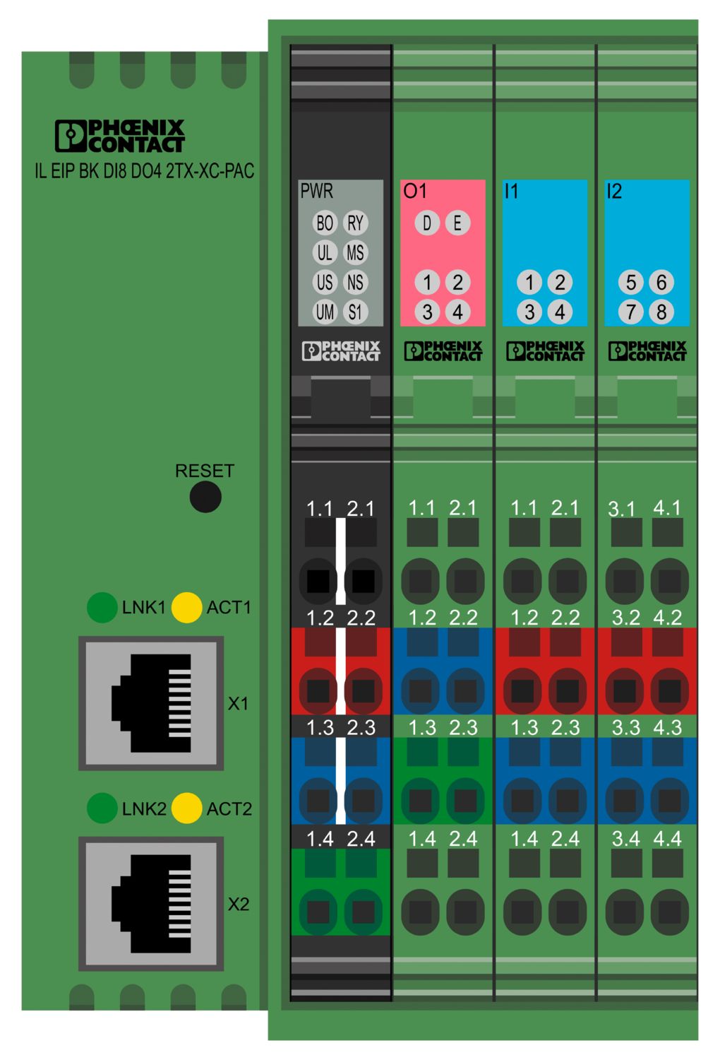
The bus coupler with integrated I/Os is intended for use within an EtherNet/IP™ network and represents the link to the Inline I/O system. Up to 61 Inline devices can be connected to the bus coupler. The bus coupler supports a maximum of 8 PCP devices. A corresponding EDS file is available for integrating the Inline station into the programming system. This file can be downloaded via the product at www.phoenixcontact.com/products. Thanks to special engineering measures and tests, the terminal can be used under extreme ambient conditions.
IL EIP BK DI8 DO4 2TX-XC-PAC
-
Bus coupler
2702131
Inline, Bus coupler, EtherNet/IP™, RJ45 jack, Digital inputs: 8, 24 V DC, connection technology: 3-conductor, Digital outputs: 4, 24 V DC, 500 mA, connection technology: 3-conductor, Extreme conditions version, transmission speed in the local bus: 500 kbps / 2 Mbps, degree of protection: IP20, including Inline connectors and marking fields
Free download available.
Downloads
Product details
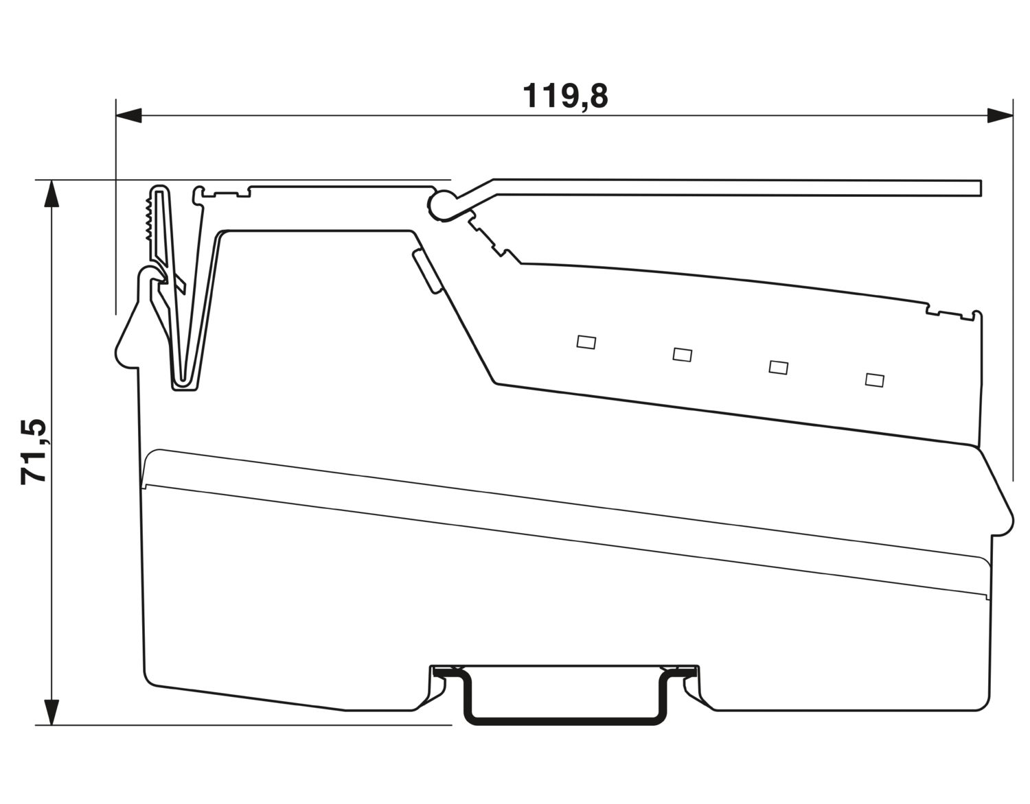
| Dimensional drawing |
|
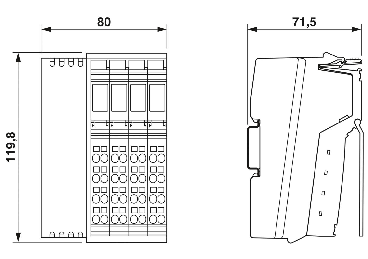
| Width | 80 mm |
| Height | 119.8 mm |
| Depth | 71.5 mm |
| Note on dimensions | Specfications with connectors |
| Color | green |
| EtherNet/IP™ | |
| Number of interfaces | 2 |
| Connection method | RJ45 jack |
| Note on the connection method | Auto negotiation and autocrossing |
| Permissible conductor cross-section | 0.14 mm² ... 0.22 mm² (twisted pair) |
| Transmission speed | 10/100 Mbps (half or full duplex (automatic detection)) |
| Transmission physics | Ethernet in RJ45 twisted pair |
| Inline local bus | |
| Connection method | Inline data jumper |
| Transmission speed | 500 kbps / 2 Mbps (automatic detection, no combined system) |
| Fieldbus: Local bus gateway | |
| Max. number of local bus devices | 61 (The on-board I/Os are two devices) |
| System limits | |
| Amount of process data () | max. 504 Byte |
| Amount of process data () | max. 504 Byte |
| Number of supported devices | max. 63 (per station) |
| Number of local bus devices that can be connected | max. 61 (The on-board I/Os are two devices) |
| Number of devices with parameter channel | max. 8 |
| Number of supported branch terminals with remote bus branch | 0 |
| Programming data | |
| Input address area | 8 bit |
| Output address area | 4 bit |
| Register length (bus) | 16 bit |
| Register length (master) | 512 Byte |
| Digital: | |
| Input name | Digital inputs |
| Description of the input | EN 61131-2 type 1 |
| Number of inputs | 8 |
| Connection method | Inline connector |
| Connection technology | 3-conductor |
| Input voltage | 24 V DC |
| Input voltage range "0" signal | -30 V DC ... 5 V DC |
| Input voltage range "1" signal | 15 V DC ... 30 V DC |
| Nominal input voltage UIN | 24 V DC |
| Nominal input current at UIN | typ. 3 mA |
| Current flow | Limited to 3 mA, maximum |
| Typical input current per channel | typ. 3 mA |
| Typical response time | approx. 500 µs |
| Delay at signal change from 0 to 1 | 1.2 ms |
| Delay at signal change from 1 to 0 | 1.2 ms |
| Protective circuit | Reverse polarity protection; Suppressor diode |
| Digital: | |
| Output name | Digital outputs |
| Connection method | Inline connector |
| Connection technology | 3-conductor |
| Number of outputs | 4 |
| Protective circuit | Short-circuit and overload protection; Freewheeling circuit in the output driver |
| Output voltage | 24 V DC -1 V (At nominal current) |
| Max. current carrying capacity per output | max. 500 mA |
| Maximum output current per module | max. 2 A |
| Nominal output voltage | 24 V DC |
| Output current when switched off | max. 10 µA (When not loaded, a voltage can be measured even at an output that is not set.) |
| Nominal load, inductive | 12 VA (1.2 H, 48 Ω) |
| Nominal load, lamp | 12 W |
| Nominal load, ohmic | 12 W |
| Reverse voltage resistance to short pulses | Reverse voltage proof |
| Behavior with overload | Auto restart |
| Behavior with inductive overload | Output can be destroyed |
| Behavior at voltage switch-off | The output follows the power supply without delay |
| Signal delay | typ. 1.2 ms |
| Overcurrent shut-down | min. 0.7 A |
| Product type | I/O component |
| Product family | Inline |
| Type | modular |
| Inline | |
| Scope of supply | including Inline connectors and marking fields |
| No. of channels | 12 |
| Special properties | Extreme conditions version |
| Diagnostics messages | Short-circuit or overload of the digital outputs yes |
| Sensor supply failure yes | |
| Failure of the actuator supply yes |
| Power dissipation | typ. 1.7 W (entire device) |
| Potentials | |
| Protective circuit | Short-circuit protection of the communications power; electronic |
| Short-circuit protection of the analog supply; electronic | |
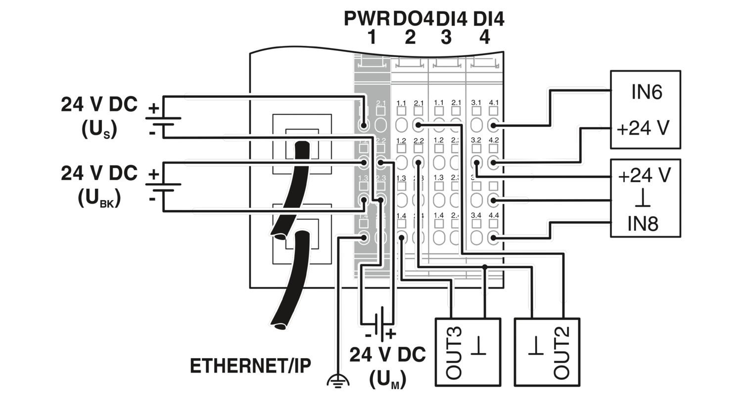
| Potentials: Bus coupler supply UBK; Communications power UL (7.5 V) and the analog supply UANA (24 V) are generated from the bus coupler supply. | |
| Supply voltage | 24 V DC (via Inline connector) |
| Supply voltage range | 19.2 V DC ... 30 V DC (including all tolerances, including ripple) |
| Current draw | max. 0.98 A |
| min. 80 mA (without connected I/O terminal blocks) | |
| Potentials: Communications power (UL) | |
| Supply voltage | 7.5 V DC |
| Power supply | max. 0.8 A DC |
| Potentials: Supply of analog modules (UANA) | |
| Supply voltage | 24 V DC |
| Supply voltage range | 19.2 V DC ... 30 V DC (including all tolerances, including ripple) |
| Power supply | max. 0.5 A DC |
| Potentials: Main circuit supply (UM) | |
| Supply voltage | 24 V DC (via Inline connector) |
| Supply voltage range | 19.2 V DC ... 30 V DC (including all tolerances, including ripple) |
| Power supply | max. 8 A DC (sum of UM + US) |
| Current draw | max. 8 A DC |
| min. 3 mA (without sensors) | |
| Potentials: Segment circuit supply (US) | |
| Supply voltage | 24 V DC (via Inline connector) |
| Supply voltage range | 19.2 V DC ... 30 V DC (including all tolerances, including ripple) |
| Power supply | max. 8 A DC (sum of UM + US) |
| Current draw | max. 8 A DC |
| min. 6 mA (without actuators) | |
| Connection technology | |
| Connection name | Inline connector |
| Inline connector | |
| Connection method | Spring-cage connection |
| Conductor cross-section, rigid | 0.08 mm² ... 1.5 mm² |
| Conductor cross-section, flexible | 0.08 mm² ... 1.5 mm² |
| Conductor cross-section AWG | 28 ... 16 |
| Stripping length | 8 mm |
| Ambient conditions | |
| Ambient temperature (operation) | -25 °C ... 60 °C (Standard) |
| -40 °C ... 70 °C (Extended, see section “Tested successfully: use under extreme ambient conditions” in the data sheet.) | |
| Degree of protection | IP20 |
| Air pressure (operation) | 70 kPa ... 106 kPa (up to 3000 m above sea level) |
| Air pressure (storage/transport) | 70 kPa ... 106 kPa (up to 3000 m above sea level) |
| Ambient temperature (storage/transport) | -40 °C ... 85 °C |
| Permissible humidity (operation) | 10 % ... 95 % (non-condensing) |
| Permissible humidity (storage/transport) | 10 % ... 95 % (non-condensing) |
| Mechanical test | |
| Vibration resistance in accordance with EN 60068-2-6/IEC 60068-2-6 | 5g |
| Shock in accordance with EN 60068-2-27/IEC 60068-2-27 | Operation: 25g, 11 ms duration, semi-sinusoidal shock impulse |
| Protection class | III (IEC 61140, EN 61140, VDE 0140-1) |
| Mounting type | DIN rail mounting |
| Item number | 2702131 |
| Packing unit | 1 pc |
| Minimum order quantity | 1 pc |
| Product key | DRI11D |
| GTIN | 4046356981071 |
| Weight per piece (including packing) | 360.3 g |
| Weight per piece (excluding packing) | 329 g |
| Country of origin | DE |
| China RoHS | |
| Environment friendly use period (EFUP) |
EFUP-E
No hazardous substances above the limits
|
| EU REACH SVHC | |
| REACH candidate substance (CAS No.) | No substance above 0.1 wt% |
Compatible products
-
-
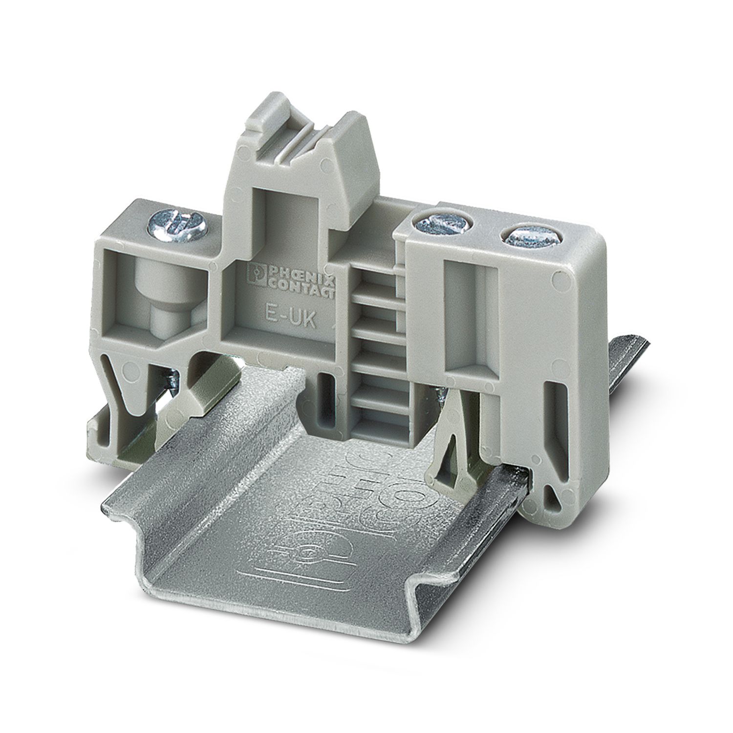
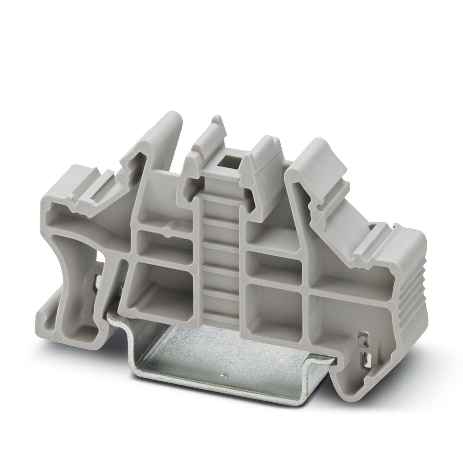
E/UK - End bracket 1201442
-
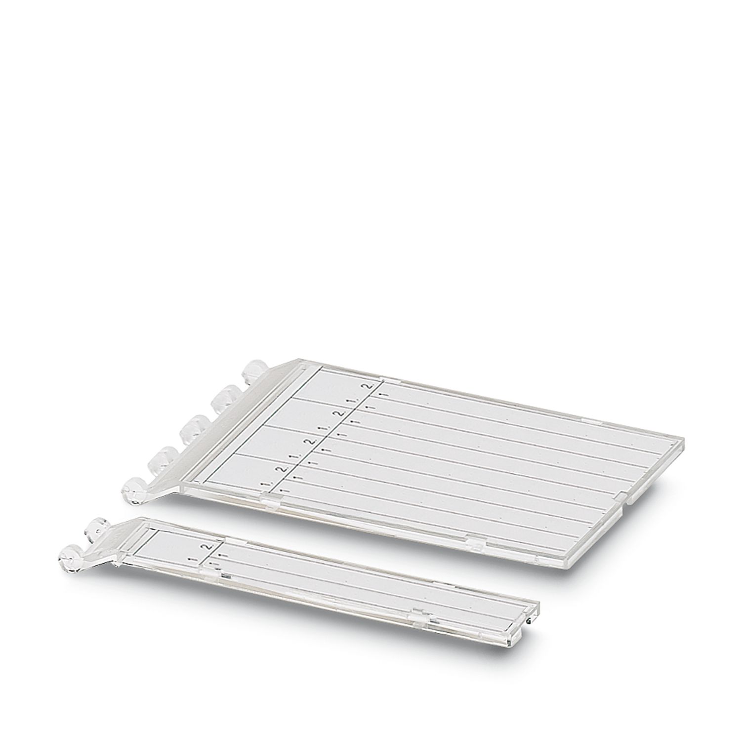
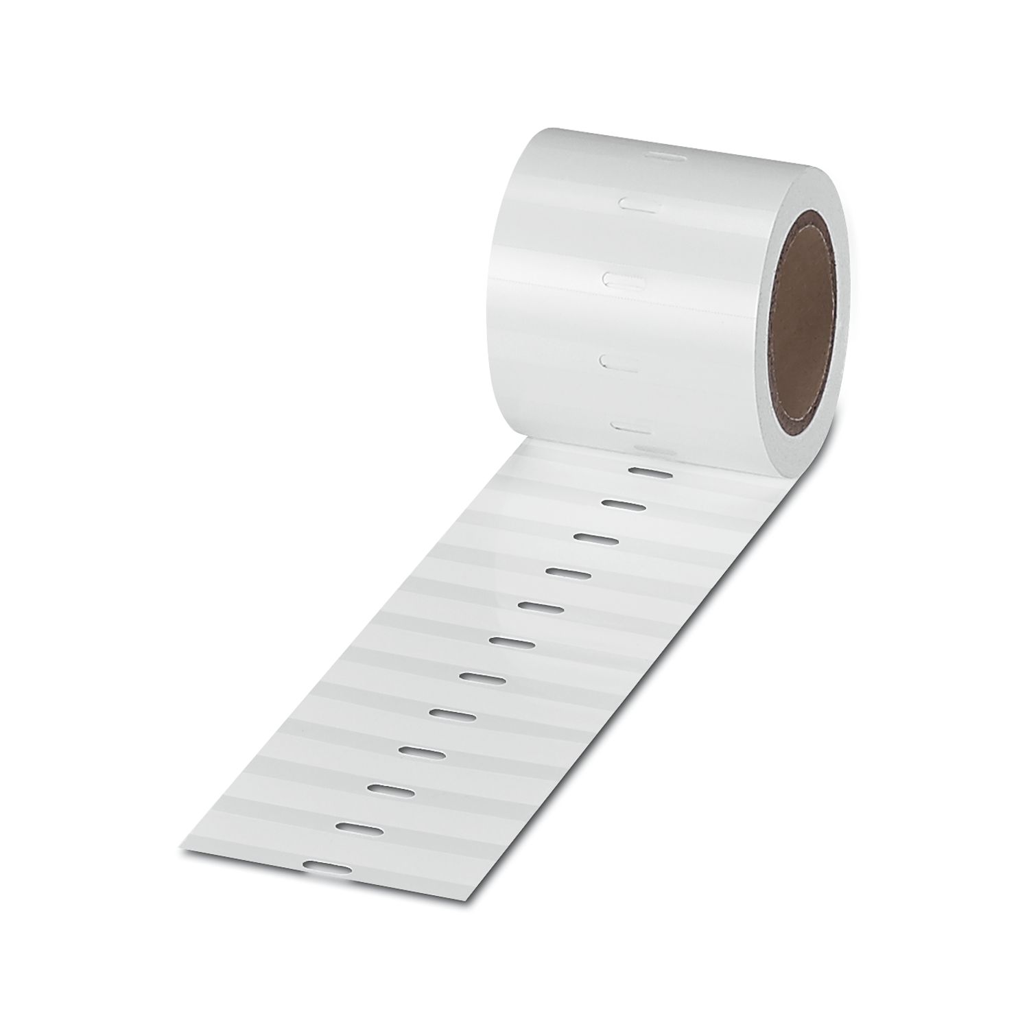
ESL 62X46 - Insert strip 0809502
-
IB IL FIELD 8 - Marking field 2727515
-
ESL 62X10 - Insert strip 0809492
-
IB IL FIELD 2 - Marking field 2727501
-
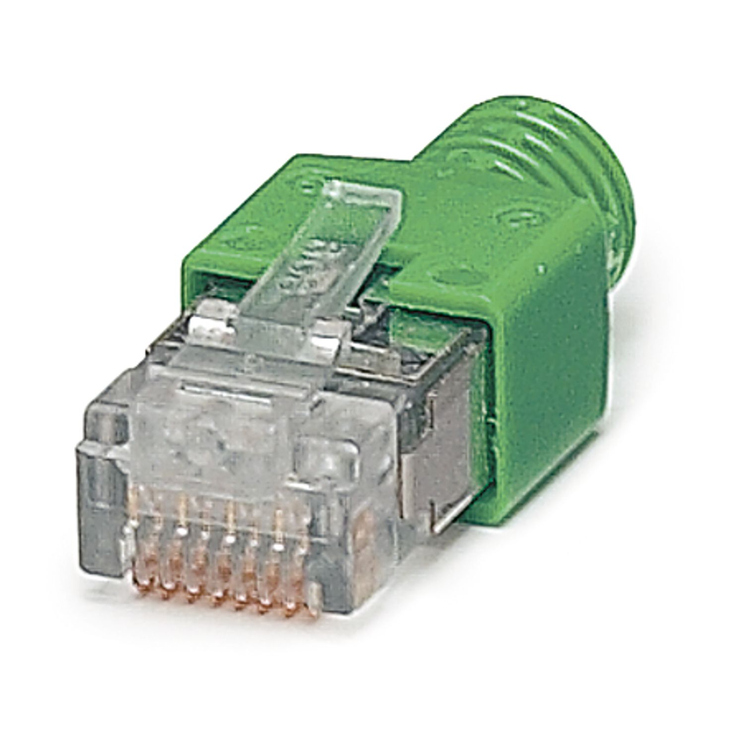
FL PLUG RJ45 GR/2 - RJ45 connector 2744856
-
FL PLUG RJ45 GN/2 - RJ45 connector 2744571
-
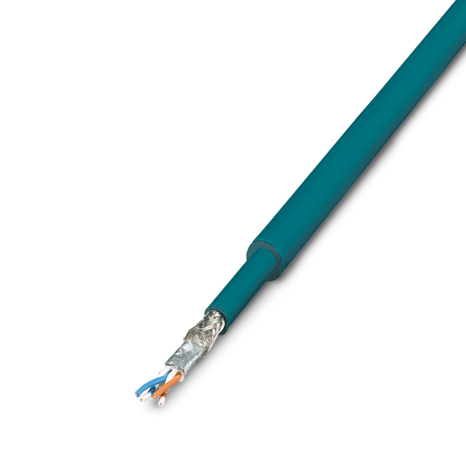
FL CAT5 HEAVY - Data cable 2744814
-
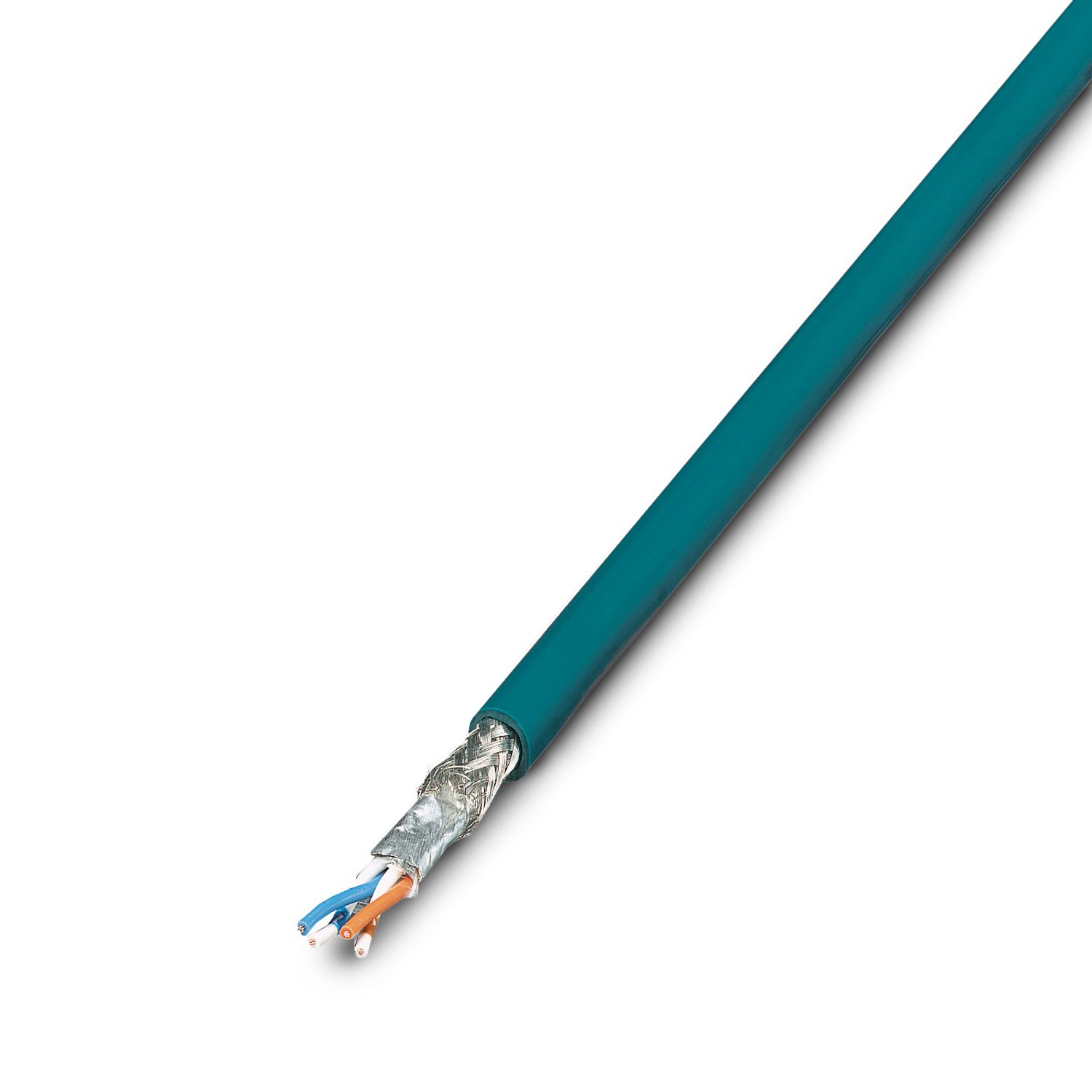
FL CAT5 FLEX - Installation cable 2744830
-
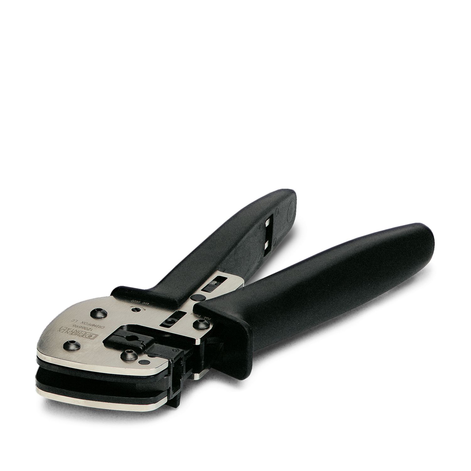
FL CRIMPTOOL - Assembly tool 2744869
-
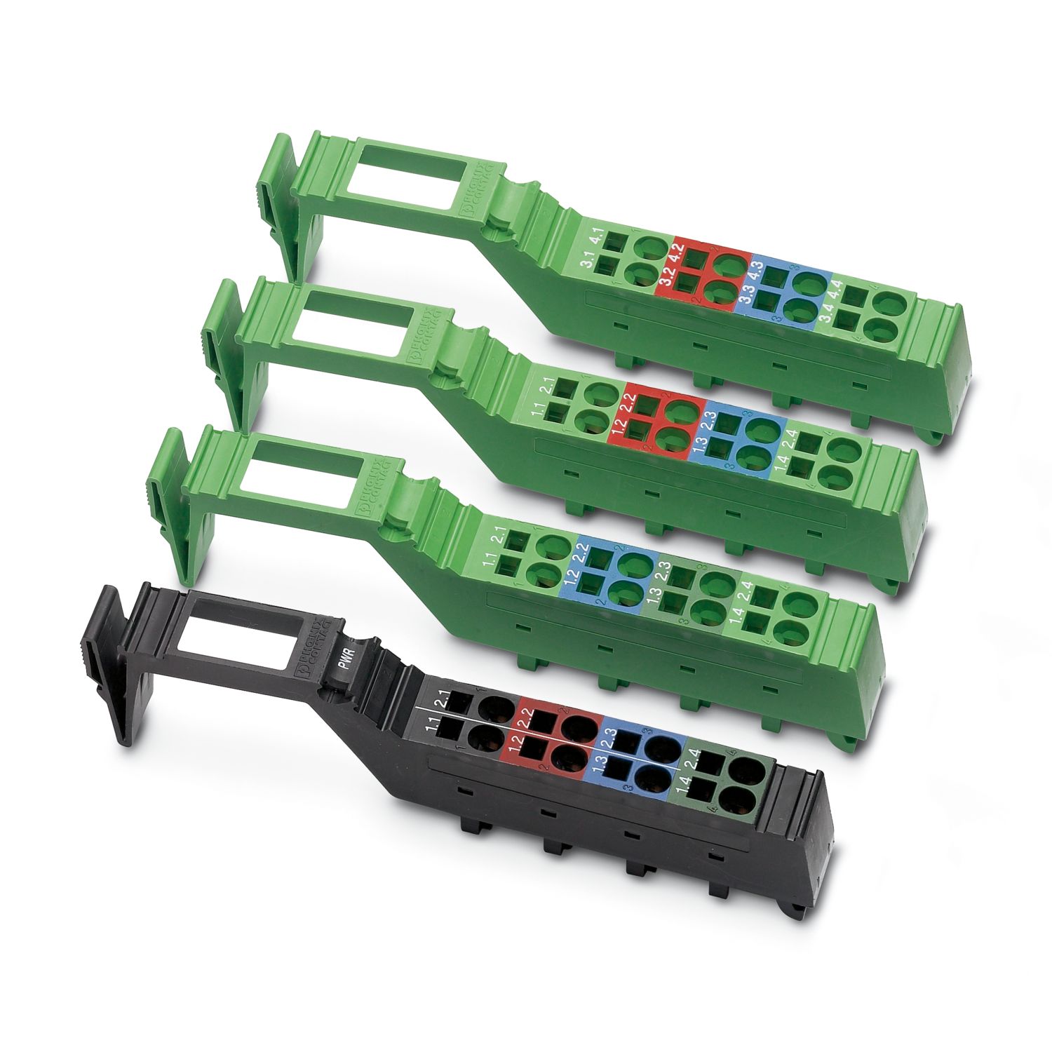
IL BKDIO-PLSET - Connector set 2878599
-
IPASSIGN - Software 2701094
Your advantages
8 digital inputs, 4 digital outputs (on-board)
EtherNet/IP™, Version 1.2
Web-based management
2 RJ45 connections
Automatic detection of the transmission speed in the local bus (500 kbps or 2 Mbps)
Can be used under extreme ambient conditions
Extended temperature range of -40 °C ... +70 °C (see “Tested successfully: use under extreme ambient conditions” in the data sheet)
Coated PCBs
PHOENIX CONTACT Trading LLC
Twin Tower Building No. 3279, 6th Floor, King Abdullah Branch Road, Al Quds District, Riyadh 13214, Kingdom of Saudi Arabia, Short Address Code: RFQA3279