
QUINT POWER power supplies with maximum functionality
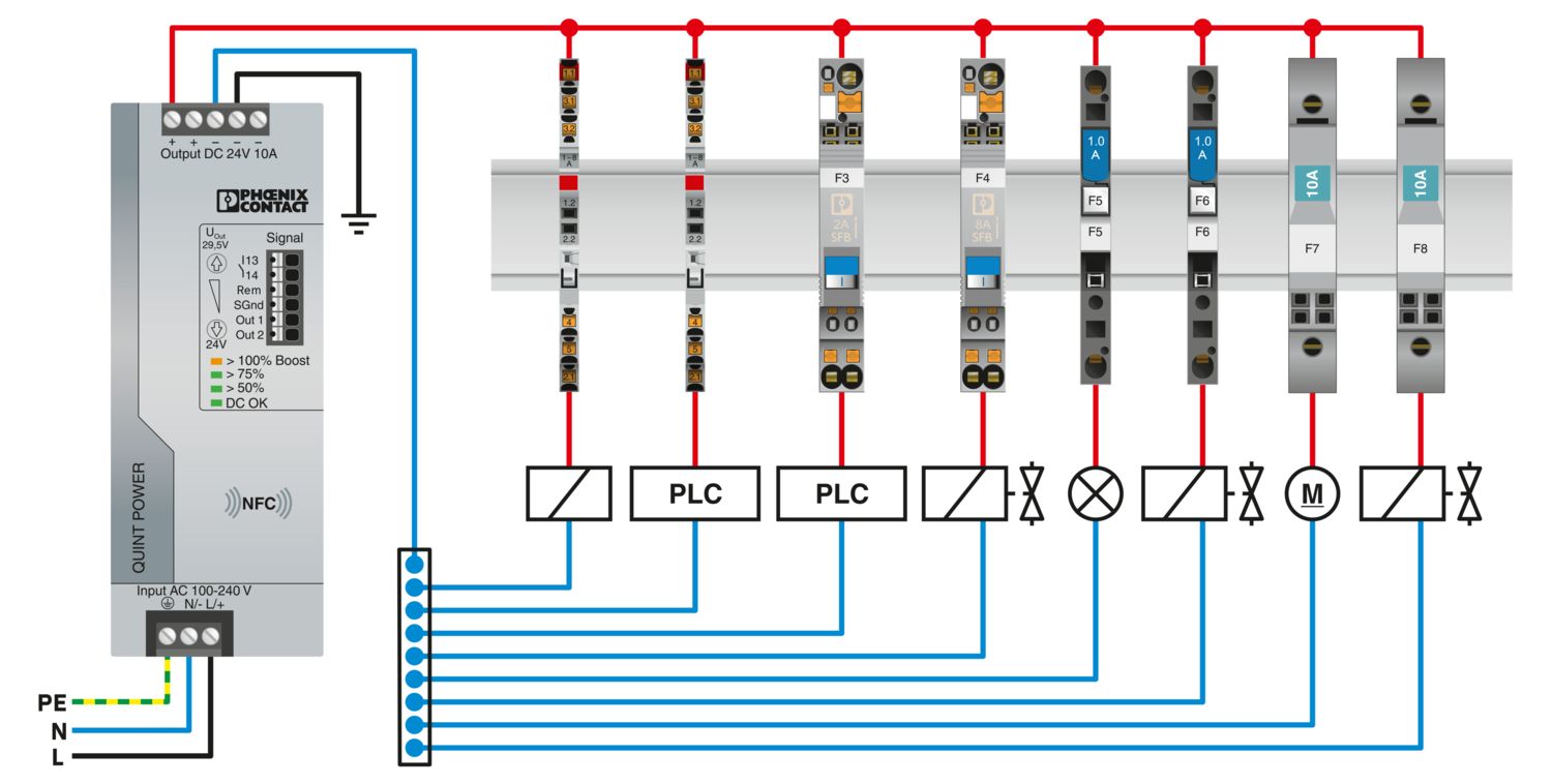
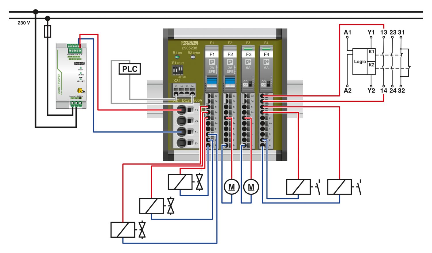
QUINT POWER circuit breakers magnetically and therefore quickly trip at six times the nominal current, for selective and therefore cost-effective system protection. The high level of system availability is additionally ensured, thanks to preventive function monitoring, as it reports critical operating states before errors occur.
Reliable starting of heavy loads takes place via the static power reserve POWER BOOST. Thanks to the adjustable voltage, all ranges between 5 V DC ... 56 V DC are covered.
QUINT-PS/1AC/24DC/10
-
Power supply
2866763
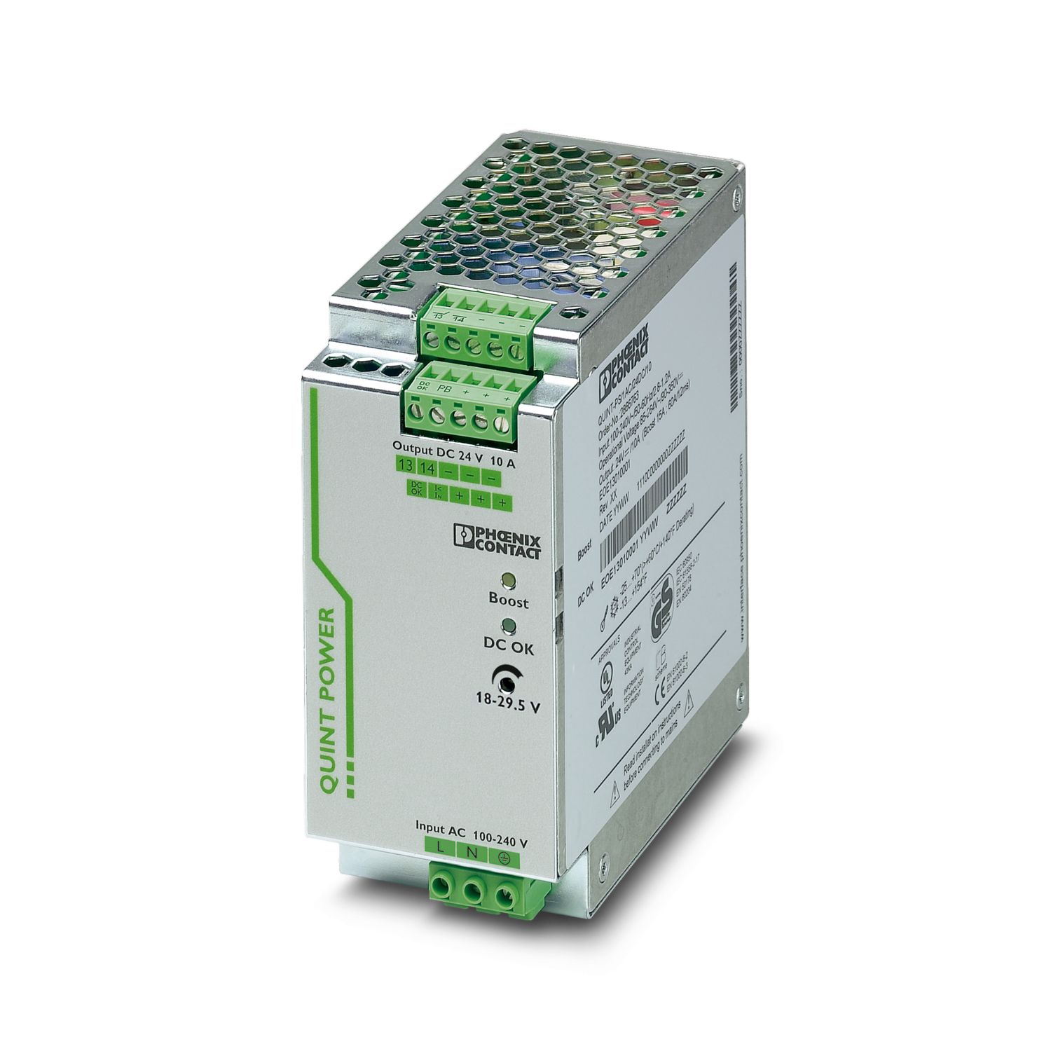
Primary-switched power supply unit QUINT POWER, Screw connection, DIN rail mounting, SFB Technology (Selective Fuse Breaking), input: 1-phase, output: 24 V DC / 10 A
Product details
UL Recognized
Approval ID: E211944EAC
Approval ID: RU S-DE.BL08.W.00764LR
Approval ID: LR22301698TA-02NK
Approval ID: TA24091MBV
Approval ID: 21004/D0 BVEAC
Approval ID: RU S-DE.BL08.W.00764UL Listed
Approval ID: E123528BSH
Approval ID: 581RINA
Approval ID: ELE333522XGABS
Approval ID: 23-2355407-PDAType approved
Approval ID: SI-SIQ BG 005/008DeviceNet
Approval ID: 10825/06.01.2010SEMI F47
Approval ID: SEMI F47DNV
Approval ID: TAA000030XcCSAus
Approval ID: 1897786BIS Licence Document
Approval ID: R-41268801


Your advantages
Reliable starting of difficult loads with the static POWER BOOST power reserve with up to 1.5 times the nominal current permanently
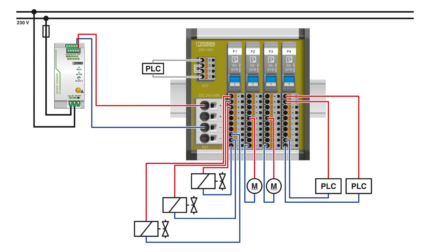
Fast tripping of standard circuit breakers with dynamic power reserve SFB (selective fuse breaking) technology with up to 6 times the nominal current for 12 ms
For superior system availability
Preventive function monitoring
Frequently asked questions
Can I trigger a standard miniature circuit breaker with the power supply?
Yes, standard miniature circuit breakers can be triggered safely with the QUINT power supply. Please refer to the SFB configuration matrix, which can be found under Various in the download area.
Can the power supply also be used in environments with corrosive gas contamination?
All our QUINT power supplies are tested in accordance with the ISA G3 Harsh Group A standard and meet the requirements of the standard.
Why is the housing of the power supply warmer than that of other manufacturers?
The reason for this is our heat dissipation concept: All power components are located on the side panels or on the rear panel. The advantage here is that the temperatures inside remain cooler, which increases the service life of the power supply.
Is this power supply also available with a coated printed circuit board and ATEX/IECEx approval?
Yes, you can use item no. 2320911 QUINT-PS/1AC/24DC/10/CO for this.
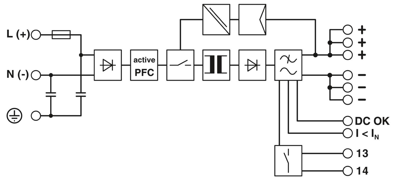
Can I operate the DC OK relay with the output voltage of the power supply?
The DC OK relay can be connected to the output voltage of the power supply, but may only be loaded with max. 1 A. We recommend using a protective circuit for this.
Can interference from the supply network be transmitted to the output of the power supply?
No, since the QUINT power supply is designed with a multi-stage converter concept, interference is not transmitted. Interference is already eliminated in the input circuit and does not reach the 24 V output of the power supply.