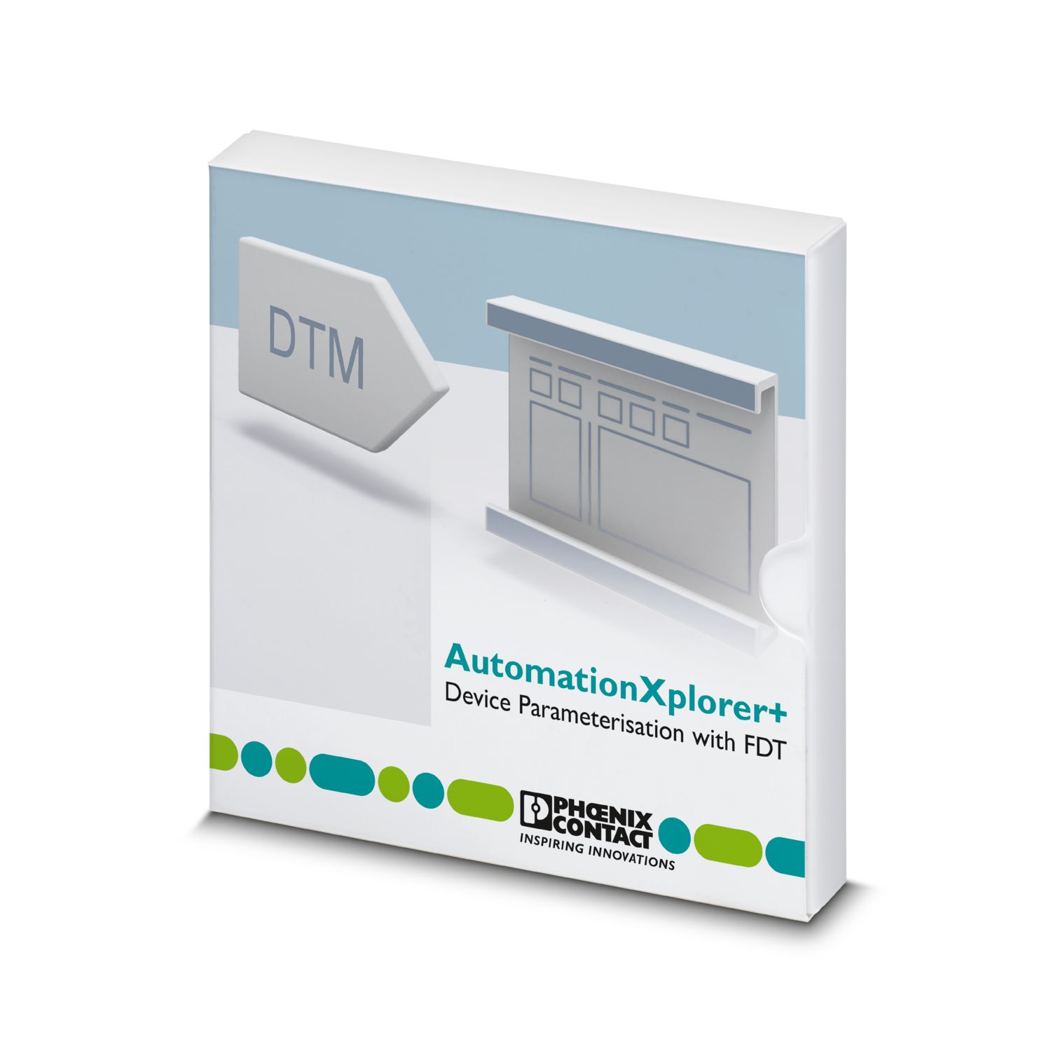
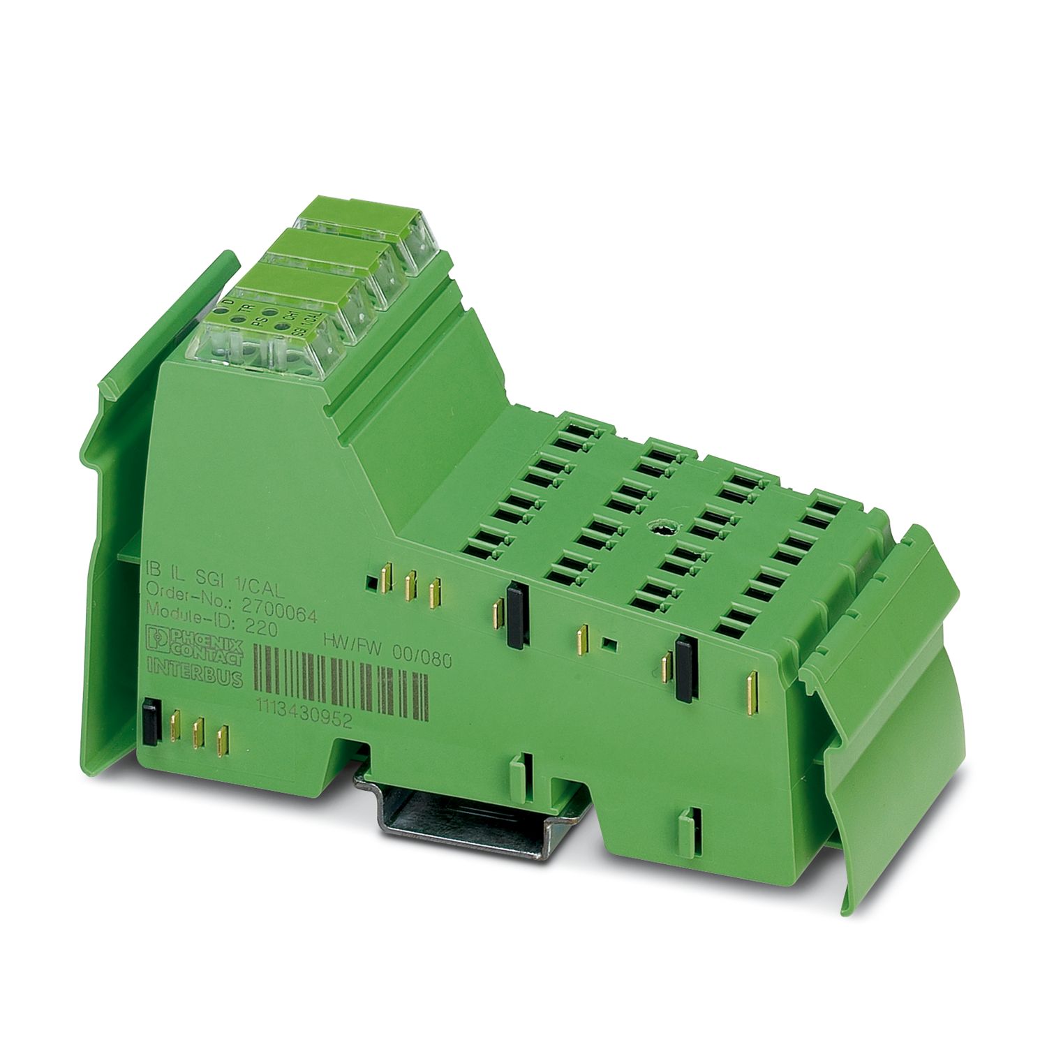
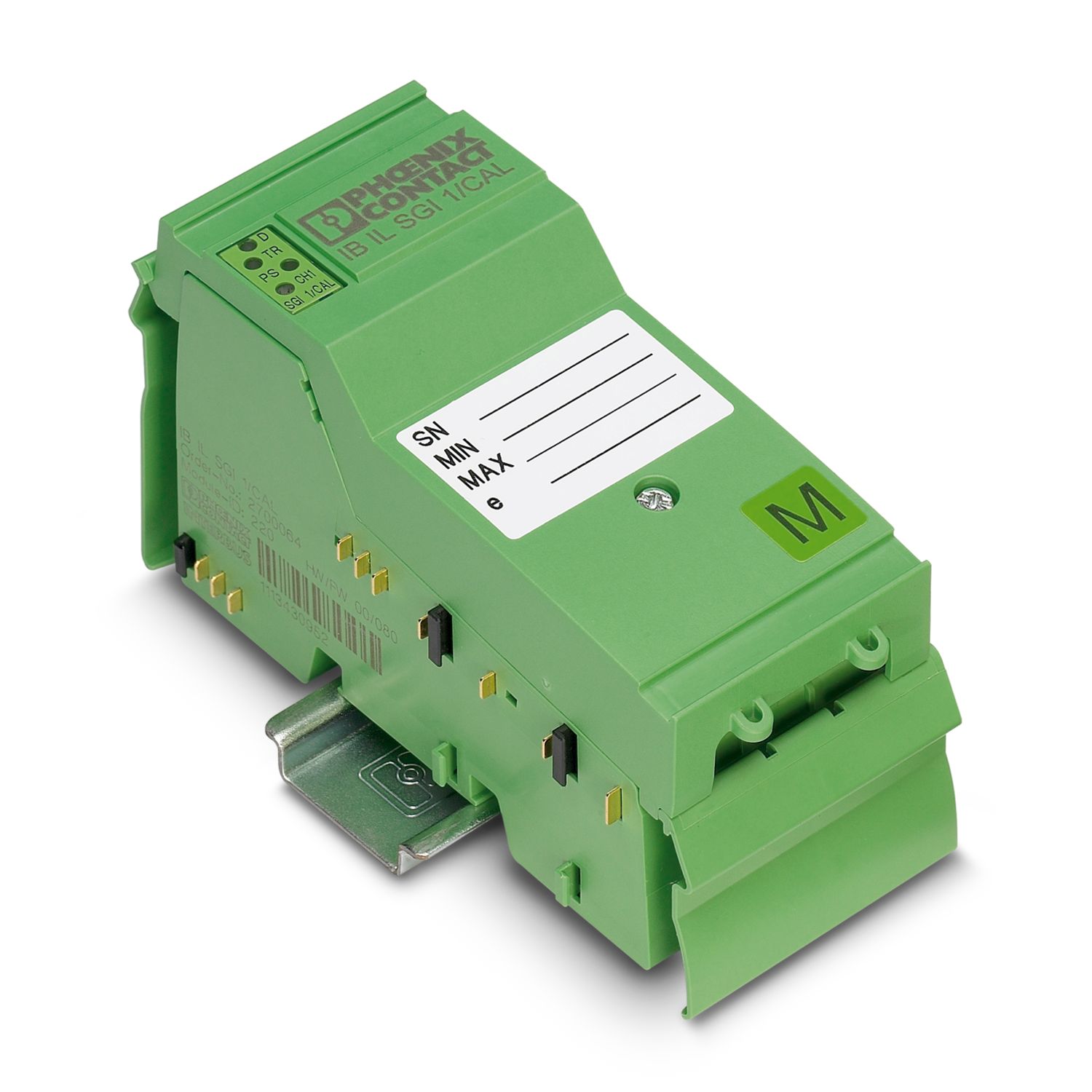
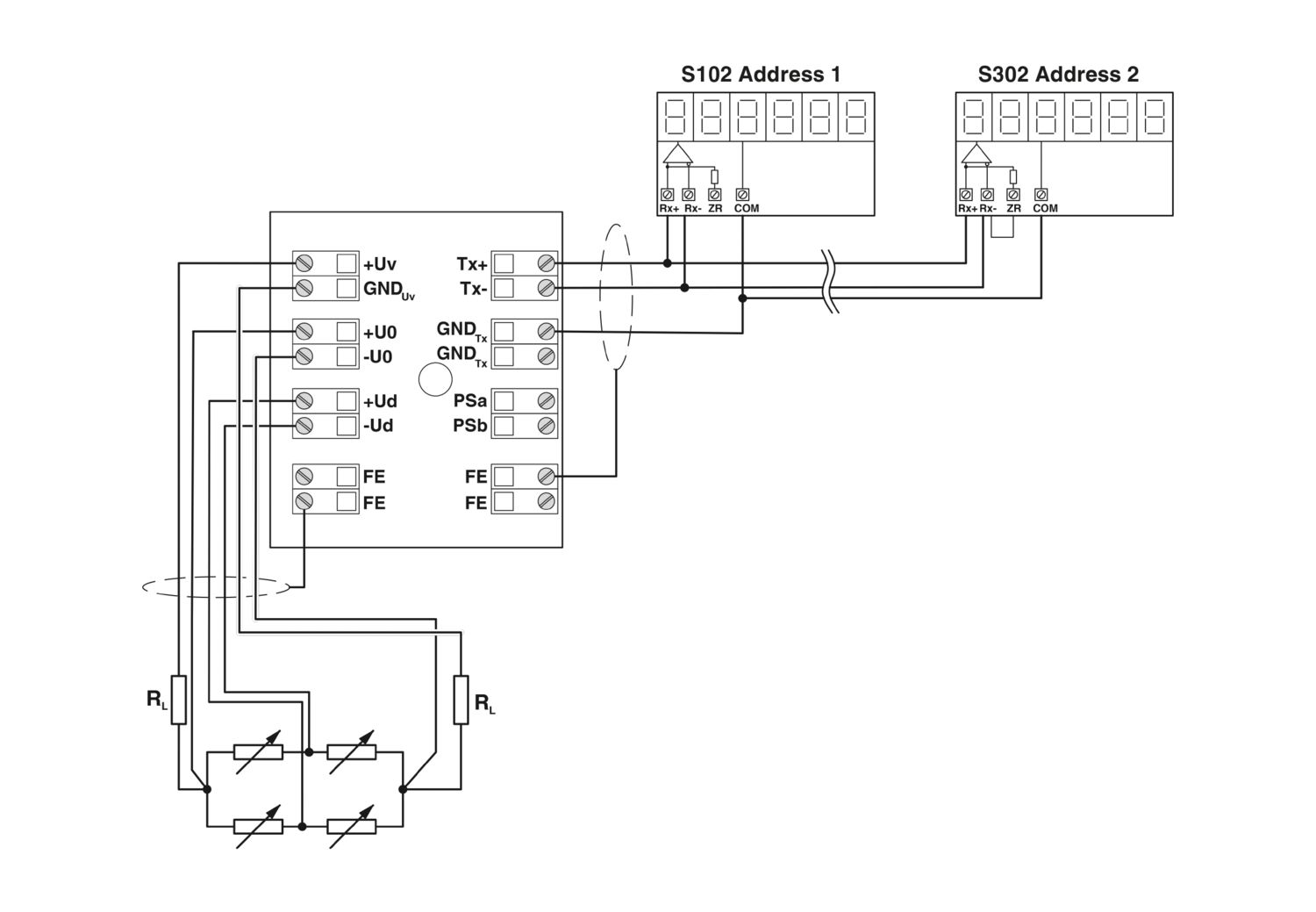
The terminal is designed for use within an Inline station. This terminal can be used as a robust and precise piece of evaluation electronics to set up non-automatic weighing instruments (NAWI). The terminal block satisfies the EC type approval as an electronic evaluating device to set up non-automatic weighing instruments (NAWI) of commercial class III with 3,000 scale intervals or class IIII ordinary scales with 1,000 scale intervals in accordance with the EN 45501 and OIML R76 standards. A network-compatible serial interface can be used to connect primary and secondary displays for displaying measured gross/net and tare values to the evaluating electronics. The measurement and configuration data is transmitted via the parameter channel (PCP). The terminal has an alibi memory to store up to 65536 measurement protocols, including date and time. A specific DTM enables easy commissioning and data management (e.g., of the measurement protocols).
IB IL SGI 1/CAL
-
Inline terminal
2700064
Inline analog strain gauge input terminal, without accessories, evaluating electronics with EC type approval
Free download available.
Downloads
Product details
Dimensional drawing |
|
Width | 48.8 mm |
Height | 120 mm |
Depth | 71.5 mm |
Note on dimensions | Dimensions with covering hood |
Utilization restriction | |
EMC note | EMC: class A product, see manufacturer's declaration in the download area |
Color | green |
Inline local bus | |
Connection method | Inline data jumper |
Transmission speed | 500 kbps |
Serial | |
Designation | RS-485 |
Network | Yes |
Addressing | Address 0 = Broadcast, alternating display of measured gross/net value and measured tare value |
Address 1 = Measured gross/net value | |
Address 2 = Measured tare value | |
Address 3 ... 9 = reserved | |
Termination resistor | 120 Ω |
Transmission protocol | STX/ETX |
Memory type | Measurement protocol memory Alibi memory: non-volatile Flash memory 20 years |
Module | |
ID code (dec.) | 220 |
ID code (hex) | DC |
Length code (hex) | 02 |
Length code (dec) | 02 |
Process data channel | 32 bit |
Input address area | 4 Byte |
Output address area | 4 Byte |
Register length | 64 bit |
Required parameter data | 23 Byte |
Required configuration data | 5 Byte |
Analog | |
Description of the input | Input channel for strain gauge |
Number of inputs | 1 |
Connection technology | 6-wire, twisted pair shielded cable |
Bridge difference Ud | Measuring range specified by selecting the characteristic |
Bridge voltage U0 | 5 V |
Measured value representation | Process data: status bits and measured value including decimal places of the gross/net display |
PCP: see PCP; test report meets the requirements of DIN EN 45501 and OIML R76 | |
Process data update | typ. 100 ms |
Characteristics | ±1 mV/V, ±2 mV/V, ±3 mV/V, ±3.33 mV/V, ±4 mV/V, ±5 mV/V |
Contacts | |
Description | Lock of parameters |
Quantity | 1 (PSa - PSb) |
Logic | PSa - PSb connected = Parameter locked |
Typical response time | < 100 ms |
Analog: | |
Protective circuit | Short-circuit protection of the voltage outputs; Yes, at least 1 minute through temperature monitoring |
Analog | |
Output description | Voltage output |
Number of outputs | 1 |
Impedance | > 55 Ω |
max. 5 kΩ | |
Output voltage | typ. 5 V ±2 % |
max. 5 V ±5 % | |
Output current | max. 90 mA |
Maximum output current | max. 90 mA |
Product type | I/O component |
Type | modular |
Inline | |
Operating mode | Process data operation with 2 words, PCP with 2 words |
Diagnostics messages | Failure of the power supply at UANA Error message in the process data |
Failure of or insufficient communications power UL I/O error message sent to the bus coupler | |
I/O error Error message in the process data | |
User error Error message in the process data |
Real-time clock | |
Description realtime clock | Second, minute, hour, day, month, year 5 years, timer buffered |
Potentials | |
Power consumption | typ. 1 W (Device in nominal operation) |
max. 2 W (Device with maximum load) | |
Potentials: Communications power (UL) | |
Supply voltage | 7.5 V DC (via voltage jumper) |
Current draw | max. 100 mA |
typ. 80 mA | |
Potentials: Supply of analog modules (UANA) | |
Supply voltage | 24 V DC (via voltage jumper) |
Supply voltage range | 19.2 V DC ... 30 V DC (including all tolerances, including ripple) |
Current draw | max. 50 mA |
typ. 12 mA (For a typical load of 350 Ω and display) | |
43 mA (for a maximum load of 55 Ω and display) | |
Electrical isolation/isolation of the voltage ranges | |
Test voltage: Logic/analog I/O (digital isolator) | 500 V AC, 50 Hz, 1 min |
Test voltage: 24 V supply (UANA)/analog I/O (DC/DC converter) | 500 V AC, 50 Hz, 1 min |
Test voltage: RS-485/analog I/O (isolating distance) | 500 V AC, 50 Hz, 1 min |
Test voltage: Contacts PSa - PSb/analog I/O (isolating distance) | 500 V AC, 50 Hz, 1 min |
Test voltage: Functional ground/analog I/O (isolating distance) | 500 V AC, 50 Hz, 1 min |
Test voltage: Logic/24 V supply (UANA) (DC/DC converter) | 500 V AC, 50 Hz, 1 min |
Test voltage: RS-485/24 V supply (UANA) (DC/DC converter) | 500 V AC, 50 Hz, 1 min |
Test voltage: Functional ground/24 V supply (UANA) (isolating distance) | 500 V AC, 50 Hz, 1 min |
Test voltage: Logic/RS-485 (digital isolator) | 500 V AC, 50 Hz, 1 min |
Test voltage: Functional ground/RS-485 (isolating distance) | 500 V AC, 50 Hz, 1 min |
Test voltage: Logic/contacts PSa - PSb (optocoupler) | 500 V AC, 50 Hz, 1 min |
Test voltage: Functional ground/contacts PSa - PSb (isolating distance) | 500 V AC, 50 Hz, 1 min |
Test voltage: Logic/functional ground (isolating distance) | 500 V AC, 50 Hz, 1 min |
Connection technology | |
Connection name | Inline connector |
Conductor connection | |
Connection method | Spring-cage connection |
Conductor cross section rigid | 0.08 mm² ... 1.5 mm² |
Conductor cross section flexible | 0.08 mm² ... 1.5 mm² |
Conductor cross section AWG | 28 ... 16 |
Stripping length | 8 mm |
Inline connector | |
Connection method | Spring-cage connection |
Conductor cross section, rigid | 0.08 mm² ... 1.5 mm² |
Conductor cross section, flexible | 0.08 mm² ... 1.5 mm² |
Conductor cross section AWG | 28 ... 16 |
Stripping length | 8 mm |
SMKDS terminals | |
Connection method | Screw connection |
Conductor cross section, rigid | 0.14 mm² ... 1.5 mm² |
Conductor cross section, flexible | 0.14 mm² ... 1 mm² |
Conductor cross section AWG | 26 ... 16 |
Stripping length | 8 mm |
Ambient conditions | |
Ambient temperature (operation) | -25 °C ... 55 °C (Type approval according to DIN EN 45501 and OIML R76: -10°C ... 40°C) |
Degree of protection | IP20 |
Air pressure (operation) | 70 kPa ... 106 kPa (up to 3000 m above sea level) |
Air pressure (storage/transport) | 70 kPa ... 106 kPa (up to 3000 m above sea level) |
Ambient temperature (storage/transport) | -25 °C ... 85 °C |
Permissible humidity (operation) | 10 % ... 95 % (non-condensing) |
Permissible humidity (storage/transport) | 10 % ... 95 % (non-condensing) |
Protection class | III (IEC 61140, EN 61140, VDE 0140-1) |
Mounting type | DIN rail mounting |
Item number | 2700064 |
Packing unit | 1 pc |
Minimum order quantity | 1 pc |
Product key | DRI144 |
Catalog page | Page 163 (C-6-2017) |
GTIN | 4046356484022 |
Weight per piece (including packing) | 182,5 g |
Weight per piece (excluding packing) | 160 g |
Country of origin | DE |
China RoHS | |
Environment friendly use period (EFUP) |
EFUP-E
No hazardous substances above the limits
|
EU REACH SVHC | |
REACH candidate substance (CAS No.) | No substance above 0.1 wt% |
Compatible products
Your advantages
1 input for DMS
Serial interface for external weight displays
Connection of strain gauges in 6-conductor technology
Electronic evaluating device to set up non-automatic weighing instruments (NAWI)
Can be calibrated by EC type approval according to standards EN 45501 and OIML R76
Alibi storage for up to 65536 test reports
Zero point, tare, and standstill display
Up to 3000 pitch values
Parameterization and calibration using FDT/DTM technology
Various filter settings
PHOENIX CONTACT B.V.
Hengelder 56, 6902 PA Zevenaar, Postbus 246, 6900 AE Zevenaar