Man installing surge protection in a control cabinet

Surge protection – basics Technology, standards, and directives for surge protection

The answers to the following questions can be found here:

  • How do surge voltages occur and what effect do they have?
  • How do you create an effective surge protection concept?
  • What is the technology behind the protection concept and products?
  • What do you need to bear in mind?
Technology, standards, and directives for surge protection
From the generation of surge voltages through to a comprehensive protection concept
You probably have many questions – ranging from the basic question of how surge voltages even occur, to technical details about grid systems or individual components of a surge protection concept. On these pages and in our e-paper, we would like to answer these questions for you. We wish you – in the truest sense of the word – an exciting read!
Call up e-paper now
Lightning strike in a city

Causes of overvoltages

Overvoltage – what is it exactly? How do surge voltages occur? How do surge voltages get into your devices and systems? You’ve probably wondered about the answers to these questions. Below you will find comprehensive information on surge protection technology.

Causes

Surge voltages only occur for a fraction of a second. For this reason, they are called transient voltages or transients. They have very short rise times of a few microseconds before they drop off again, relatively slowly, over a period of up to 100 microseconds.
Surge voltages occur as a result of:

Lightning discharges (LEMP)
The technical term for lightning discharge is LEMP. This stands for lightning electromagnetic pulse.
Lightning strikes during storms cause extremely high transient overvoltages. They are much higher than surge voltages that are caused by switching operations or electrostatic discharge. However, they occur a lot less frequently than other causes.

Switching operations (SEMP)
Switching operations are referred to with the abbreviation SEMP. This stands for switching electromagnetic pulse.
In this context, switching operations mean the switching of powerful machines or short circuits in the power supply network. During such operations, significant current changes occur in the affected cables in a split second.

Electrostatic discharges (ESD)
The abbreviation ESD stands for electrostatic discharge.
Here, an electrical charge is transferred when bodies with a different electrostatic potential approach or come into contact with one another. A familiar example of this is when a person becomes charged while walking over a wall-to-wall carpet and then discharges to a metal grounded object, such as a metal rail.

Coupling types

Surge voltages can get into circuits in various ways. These are known as coupling types.

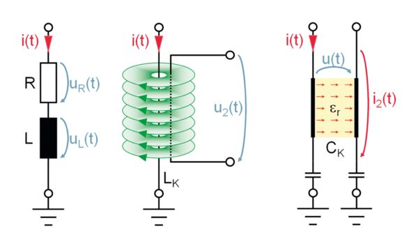
Coupling types of overvoltages

Galvanic coupling (left), inductive coupling (center), and capacitive coupling (right)

Galvanic coupling
This refers to surge voltages which are directly coupled into a circuit. This can be observed during lightning strikes, for example. In this case, lightning current amplitudes at the grounding resistance of the affected building cause an overvoltage.
This voltage affects all cables that are connected to the central equipotential bonding. An overvoltage also occurs along conductors carrying lightning current. Due to the fast rate of current rise, this can mainly be traced back to the inductive component of the cable resistance. Faraday’s law of induction is used as the basis for calculating this: u0 = L x di/dt.

Inductive coupling
This process occurs through the magnetic field of another current-carrying conductor, following the transformer principle. A directly coupled overvoltage causes a surge current with a high rate of increase in the affected conductor.
At the same time, a strong magnetic field is created around this conductor, as is the case in the primary winding of a transformer. The magnetic field induces an overvoltage in other cables in its vicinity, as is the case in the secondary winding of a transformer. The coupled overvoltage is channeled along the cables into the connected device.

Capacitive coupling
This type of coupling primarily occurs via the electric field between two points with a large potential difference. A high potential occurs via the down conductor of a lightning arrester due to a lightning strike. An electrical field is created between the down conductor and other parts with a low potential.
These may be, for example, cables for power supply and signal transmission or devices inside the building. The charge is transferred through the electrical field. This leads to a voltage increase or ultimately an overvoltage in the affected cables and devices.

Direction of action of surge voltages

Surge voltages act in two directions in affected circuits.

Direction of action of overvoltages with common mode voltage and normal-mode voltage

Common-mode voltage (left) and normal-mode voltage (right)

Common mode voltage
Common-mode voltages [UL] occur in the event of interference caused by surge voltages or high-frequency interference voltages between active conductors and ground. The term asymmetrical is also often used.
Asymmetrical voltages primarily endanger components that are located between active potentials and a grounded ground, as well as the insulation between active potentials and ground. This results in sparkovers on PCBs or between voltage-carrying equipment and grounded housing parts.

Normal mode voltage
Normal-mode voltages [UQ] occur in the event of interference caused by surge voltages or high-frequency interference voltages between the active conductors of a circuit. The terms symmetrical and differential-mode are also used.
Symmetrical surge voltages endanger the voltage and signal input of devices and interfaces. This results in direct overload and destruction of the affected equipment, e.g., in the power supply or signal-processing components.

Effects of overvoltages

More often than not, overvoltages which couple into a circuit cause considerable damage to equipment and devices. Devices that are in constant use are at particularly high risk. Here, this damage can result in extremely high costs.
It is not just the replacement or repair of damaged devices that costs money. Even more expensive are long system downtimes or even the loss of software or data.

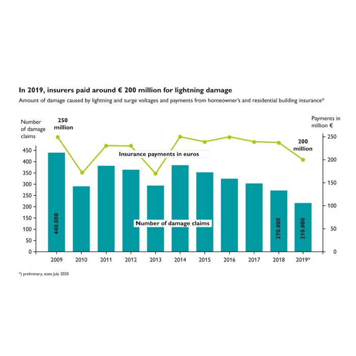
Diagram: Incidence of loss caused by overvoltages (source: GDV/2019)

Incidence of loss caused by overvoltages (source: GDV/2019)

Incidence of loss

Every year, the statistics from insurers show high figures for the incidence of loss caused by overvoltages. In the majority of cases, operators of electronic systems are compensated by their insurance for damage to the hardware. However, software damage and system failure frequently remain uninsured, leading to great financial burdens.
According to statistics from German insurers for 2019, the proportion of lightning and surge damage alone makes up a notable proportion. Even though the number of claims has fallen slightly in recent years, around 200 million euros have been paid out annually for household contents and residential building insurance claims. (Source: German Insurance Association, GDV)

Damage caused by overvoltages on an electronic component

Damage caused by overvoltages on an electronic component

Risk potential

Each circuit works with its own specific voltage. Therefore, any voltage increase that exceeds the upper tolerance limit is an overvoltage.
The extent of the damage depends largely on the electric strength of the components used and the energy that can be converted in the affected circuit.

Representation of the protective circuit principle for surge protection

Representation of the protective circuit principle

Protection concept

The protective circuit principle describes a concept for complete protection against overvoltages. An imaginary circle should be drawn around the item to be protected. Surge protective devices should be installed at all points where cables intersect this circle. The nominal data of the relevant circuit must be taken into consideration when selecting the protective devices. The area within the protective circuit is therefore protected in such a way that conducted surge voltage couplings are prevented.
The protective circuit concept can be broken down into the following areas:

  • Power supply
  • Measurement and control technology
  • Information technology
  • Transmitter and receiver systems
Location of the individual protection zones using the example of a typical single-family home

Location of the individual protection zones using the example of a typical single-family home

Protection zones

In order to achieve effective protection, it is important to determine where devices that are in danger are located and what influences represent a danger to the devices. The following figure shows a typical single-family home used as an example to illustrate the location of the individual protection zones.

The abbreviation LPZ stands for lightning protection zone and refers to the various danger zones. A distinction is made between the following zones:

  • LPZ 0A (direct lightning strike): Refers to the danger zone outside the building.
  • LPZ 0B (direct lightning strike): Refers to the protected danger zone outside the building.
  • LPZ 1: Refers to a zone inside the building where high-energy overvoltages represent a danger.
  • LPZ 2: Refers to a zone inside the building where low-energy overvoltages represent a danger.
  • LPZ 3: In this zone, overvoltages and other influences caused by the devices and cables themselves represent a danger.
Diagram: Causes of induction voltages in cables

Causes of induction voltages in cables

Effects of surge currents in cables

Overvoltages are limited by discharging high-frequency currents and therefore transient processes. This means that it is not the ohmic resistance but the inductive resistance of a cable that is of primary importance.
According to Faraday’s law of induction, when these types of surge currents are discharged to ground potential, overvoltages are created again between the coupling point and ground.

u0 = L x di/dt

u0 = induced voltage in V
L = inductance in Vs/A in H
di = current change in A
dt = time interval in s

The inductive resistance can only be reduced by shortening the cable length or connecting discharge paths in parallel. To minimize the total impedance of the discharge path and therefore the residual voltage, mesh-shaped equipotential bonding that is as tightly meshed as possible is the best technical solution.

Equipotential bonding systems in a house

Equipotential bonding systems

Equipotential bonding

Complete protection can only be achieved through complete isolation or through complete equipotential bonding. However, since complete isolation is impossible for many practical applications, only complete equipotential bonding remains.
To achieve this, all electrically conductive parts must be connected to the equipotential bonding system. Protective devices are used to connect live cables to the central equipotential bonding. In the event of an overvoltage, they are conductive and short circuit the overvoltage. Damage from overvoltages can therefore be prevented effectively.
Various equipotential bonding systems can be created:

  • Line-shaped equipotential bonding
  • Star-shaped equipotential bonding
  • Mesh-shaped equipotential bonding

Mesh-shaped equipotential bonding is the most effective method, as all electrically conductive parts have a separate cable here and additional cables connect all end points via the shortest route. This type of equipotential bonding is suitable for particularly sensitive systems, such as computer centers.

Multi-level protection concept for the power supply

The measures required to protect devices and systems are divided into two or three levels depending on the protective devices chosen and the environmental influences to be expected. The protective devices for the individual levels differ with regard to the discharge capacity level and the voltage protection level depending on which protection level they belong to.
Three-level protection concept with separately installed protection levels:

  • Type 1: Lightning current arrester
    Voltage protection level <4 kV, typical installation location: main distribution
  • Type 2: Surge protective device
    Voltage protection level <2.5 kV, typical installation location: subdistribution
  • Type 3: Device protection
    Voltage protection level <1.5 kV, typical installation location: upstream of the end device
    Protection levels 1 and 2 can also be implemented in a type 1+2 combined lightning current and surge arrester. This protective device meets the same requirements as type 1 and type 2 arresters. The main advantage is the easy installation. In addition, no special installation conditions have to be taken into consideration.
    Three-level protection concept with type 1+2 combined lightning current and surge arrester and separate type 3 arrester:
  • Type 1+2 combined lightning current and surge arresters
    Voltage protection level <2.5 kV, typical installation location: main distribution
  • Type 3: Device protection
    Voltage protection level <1.5 kV, typical installation location: upstream of the end device
Lightning strike in a city

Download Surge protection basics

Our brochure on the basics will give you insight into lightning and surge protection for electrical installations. Discover the most important facts in a nutshell. Discover what solutions there are for the diverse challenges facing this sector. Or deepen your knowledge of the interrelationships and background; something only the specialists know.

We wish you – in the truest sense of the word – an exciting read!

Components and protective circuits

When overvoltages occur, the affected devices and cables must be short-circuited with the equipotential bonding within a very short time. Various components with suitable properties are available for this. Essentially, these components differ in terms of their response behavior and discharge capacity.

Graphic symbol for and U/I characteristic curve of a suppressor diode

Graphic symbol for and U/I characteristic curve of a suppressor diode

Suppressor diodes

Properties:

  • The function is commonly referred to as fine protection.
  • Responds very quickly.
  • Low voltage limitation.
  • Standard version with low current carrying capacity and high capacitance.
  • At a nominal voltage of 5 V the maximum discharge capacity is approximately 750 A.
  • At higher nominal voltages the discharge capacity drops significantly.

Special features:

There are also diodes with a higher nominal voltage and greater discharge capacity. However, these versions are considerably larger and are therefore hardly ever used in combined protective circuits.

Key:

UR = reverse voltage
UB = breakdown voltage
UC = clamping voltage
IPP = surge current pulse
IR = reverse current

Graphic symbol for and U/I characteristic curves of metal oxide varistors

Graphic symbol for and U/I characteristic curves of metal oxide varistors

Varistors

Properties:

  • The function is commonly referred to as medium protection.
  • Response times in the lower nanosecond range.
  • Responses are faster than gas-filled protective devices.
  • Do not cause line follow currents.

Special features:

Varistors with a nominal discharge current of up to 2.5 kA are used as a medium protection level in MCR technology. In the field of power supply, varistors with a nominal discharge current of up to 3 kA are a key component of protective circuits in type 3 arresters for device protection. Varistors used in type 2 surge protective devices are considerably more powerful. In this area of application, the standard version can withstand nominal discharge currents of up to 20 kA. For special applications, type 2 protective devices with up to 80 kA are also available.

Key:

A = high-resistance operating area
B = low-resistance operating area/limiting area

Graphic symbol for and ignition curve of a gas-filled surge protective device

Graphic symbol for and ignition curve of a gas-filled surge protective device

Gas-filled surge protective devices

Properties:

  • The function is commonly referred to as medium protection.
  • Response times in the medium nanosecond range.
  • Standard versions discharge currents of up to 20 kA.
  • Despite its high discharge capacity, the component has very compact dimensions.

Special features:

With this component, stress-dependent ignition behavior leads to residual voltages that can reach several 100 V.

Key:

  1. Static response behavior
  2. Dynamic response behavior
Graphic symbol for and characteristic ignition curve of a spark gap

Graphic symbol for and characteristic ignition curve of a spark gap

Spark gaps

Properties:

  • Key component of a lightning current arrester
  • High extinguishing capacity for line follow currents
  • Relatively high response speed
  • Stress-dependent ignition behavior

Special features:

In most cases, the key component of a powerful lightning current arrester is a spark gap. This component contains two spark horns that face one another and are positioned closely together. Overvoltages cause a sparkover between the spark horns and an electric arc is created. This plasma field short-circuits the overvoltage. Very high and steep rising currents flow here, with values into the three-figure kA range. There are open and closed spark gaps. Physically, the discharge and extinguishing capacity of open spark gaps is greater.

Arc chopping technology has proven to be particularly effective for spark gaps. In this case, a so-called baffle plate is also positioned opposite the electrodes. The electric arc between the electrodes is channeled toward this baffle plate, where it is dispersed. This results in the formation of electric arc fragments, which are blown away from the spark gap and can then be easily extinguished. This enables the spark gap to exhibit a high resistance again once the overvoltage is no longer present.

Key:

UZ = sparkover voltage/strike voltage
tZ = response time

Two-level protective circuit with ohmic decoupling (left) and three-level protective circuit with inductive decoupling (right)

Two-level protective circuit with ohmic decoupling (left) and three-level protective circuit with inductive decoupling (right)

Combined protective circuits for signal interfaces

Various components are used depending on the application. They can be used individually or combined in complex protective circuits.

The desired component-specific advantages can be brought together by combining various components. Combined gas discharge tube and suppressor diode circuits, for example, represent a standard protective circuit for sensitive signal interfaces. This combination provides high-performance and fast-responding protection with the best possible voltage protection level.

The components are indirectly switched in parallel as protection levels. In other words, an ohmic or inductive decoupling element is looped in between the components. This causes the staggered protection levels to respond at different times.

The protective circuits differ primarily according to:

  • Number of protection levels
  • Direction of action of the circuit (common-mode/normal-mode protection)
  • Nominal voltage
  • Damping effect on signal frequencies
  • Voltage protection level (clamping voltage)
Voltage distribution in a two-level protective circuit

Voltage distribution in a two-level protective circuit

Function of multi-level protective circuits

When an overvoltage occurs, the suppressor diode responds first as the fastest component. The discharge current flows through the suppressor diode and the upstream decoupling resistor. A voltage drop occurs via the decoupling resistor. This corresponds to the difference between the various sparkover voltages of the suppressor diode and the gas-filled surge protective device.

In this way, the sparkover voltage of the gas discharge tube is reached before the surge current overloads the suppressor diode. This means that when the gas-filled surge protective device has responded, the discharge current flows almost entirely through the gas discharge tube. The residual voltage via the gas discharge tube is a maximum of 20 V, which relieves the suppressor diode. In the event of a low discharge current that does not overload the suppressor diode, the gas-filled surge protective device does not respond.

The illustrated circuit offers the advantages of a fast response with low voltage limitation and has a high discharge capacity. A three-level protective circuit with inductive decoupling works according to the same principle. However, the commutation takes place in two steps: First from the suppressor diode to the varistor, and then on to the gas-filled surge protective device.

The voltage distribution principle also works between the different protection levels around the power supply. UW drops via the cable between the type 1 and type 2 protective devices and between the type 2 and type 3 protective devices. However, there are also surge protective devices for the power supply where coordination between the protection stages is possible without lengths of cable.

Key:

UG = sparkover voltage of the gas-filled surge protective device
UD = clamping voltage of the suppressor diode
UW = difference in voltage over the decoupling resistance

Standards and directives General standards for lightning protection, installation specifications, and product selection of surge protective devices

The various standards explain the requirements for installation and safety as well as the use of products in various applications in detail. The main individual topic areas are listed below along with the associated international standards.

Diagram illustrating standards, directives, and regulations for surge protection
Diagram illustrating standards, directives, and regulations
Diagram illustrating standards, directives, and regulations for surge protection

Protection against lightning - Part 1: General principles
• IEC 62305-1
• EN 62305-1
• DIN EN 62305-1 (VDE 0185-305-1)

Protection against lightning - Part 2: Risk management
• IEC 62305-2
• EN 62305-2
• DIN EN 62305-2 (VDE 0185-305-2)

Protection against lightning - Part 2: Risk management - Supplement 1: Lightning threat in Germany
• DIN EN 62305-2 Supplement 1 (VDE 0185-305-2 Supplement 1)

Protection against lightning - Part 2: Risk management - Supplement 2: Calculation assistance for assessment of risk for structures, with CD-ROM
• DIN EN 62305-2 Supplement 2 (VDE 0185-305-2 Supplement 2)

Protection against lightning - Part 2: Risk management; Supplement 3: Additional information for the application of DIN EN 62305-2 (VDE 0185-305-2)
Protection against lightning - Part 2: Risk management; Supplement 3: Additional information for the application of DIN EN 62305-2 (VDE 0185-305-2)
• DIN EN 62305-2 Supplement 3 (VDE 0185-305-2 Supplement 3)

Protection against lightning - Part 3: Physical damage to structures and life hazard
• IEC 62305-3
• EN 62305-3
• DIN EN 62305-3 (VDE 0185-305-3)

Protection against lightning - Part 3: Physical damage to structures and life hazard - Supplement 1: Additional information for the application of DIN EN 62305-3
Protection against lightning - Part 3: Physical damage to structures and life hazard - Supplement 1: Additional information for the application of DIN EN 62305-3 (VDE 0185-305-3)
• DIN EN 62305-3 Supplement 1 (VDE 0185-305-3 Supplement 1)

Protection against lightning - Part 3: Physical damage to structures and life hazard - Supplement 2: Additional information for special structures
• DIN EN 62305-3 Supplement 2 (VDE 0185-305-3 Supplement 2)

Protection against lightning - Part 3: Physical damage to structures and life hazard - Supplement 3: Additional information for the testing and maintenance of lightning protection systems
• DIN EN 62305-3 Supplement 3 (VDE 0185-305-3 Supplement 3)

Protection against lightning - Part 3: Physical damage to structures and life hazard - Supplement 4: Use of metallic roofs in lightning protection systems
• DIN EN 62305-3 Supplement 4 (VDE 0185-305-3 Supplement 4)

Protection against lightning - Part 3: Physical damage to structures and life hazard; Supplement 5: Lightning and overvoltage protection for photovoltaic power supply systems
• DIN EN 62305-3 Supplement 5 (VDE 0185-305-3 Supplement 5)

Protection against lightning - Part 3: Physical damage to structures and life hazard; Supplement 6: Additional information on the requirement for lightning protection according to DIN EN 62305-3 (VDE 0185-305-3)
• DIN EN 62305-3 Supplement 6 (VDE 0185-305-3 Supplement 6)

Protection against lightning - Part 4: Electrical and electronic systems within structures
• IEC 62305-4
• EN 62305-4
• DIN EN 62305-4 (VDE 0185-305-4)

Protection against lightning - Part 4: Electrical and electronic systems within structures - Supplement 1: Sharing of the lightning current
• DIN EN 62305-4 Supplement 1, VDE 0185-305-4 Supplement 1

Diagram illustrating standards, directives, and regulations for surge protection

Low-voltage surge protective devices - Part 11: Surge protective devices connected to low-voltage power systems - Requirements and test methods
• IEC 61643-11
• EN 61643-11
• DIN EN 61643-11 (VDE 0675-6-11)

Low-voltage surge protective devices - Part 12: Surge protective devices connected to low-voltage power distribution systems - Selection and application principles
• IEC 61643-12
• EN: not available
• DIN EN 61643-12 (VDE 0675-6-12)

Low-voltage surge protective devices - Part 21: Surge protective devices connected to telecommunications and signaling networks - Performance requirements and testing methods
Low voltage surge protective devices - Part 21: Surge protective devices connected to telecommunications and signalling networks - Performance requirements and testing methods
• IEC 61643-21
• EN: not available
• DIN EN 61643-21 (VDE 0845-3-1)

Low-voltage surge protective devices - Part 22: Surge protective devices connected to telecommunications and signaling networks - Selection and application principles
Low-voltage surge protective devices - Part 22: Surge protective devices connected to telecommunications and signalling networks - Selection and application principles
• IEC 61643-22 & CLC/TS 61643-22
• EN: not available
• DIN CLC/TS 61643-22 (VDE V 0845-3-2)

Low-voltage surge protective devices - Part 31: Requirements and test methods for SPDs for photovoltaic installations
• IEC 61643-31
• EN 61643-31
• DIN EN 61643-31 (VDE 0675-6-31)

Low-voltage surge protective devices - Surge protective devices for specific use including d.c. - Part 32: Selection and application principles - SPDs connected to photovoltaic installations
• IEC 61643-32
• EN: not available
• DIN EN 61643-32 (VDE 0675-6-32)

Wind energy generation systems - Part 24: Lightning protection
• IEC 61400-24
• EN IEC 61400-24
• DIN EN IEC 61400-24 (VDE 0127-24)

Diagram illustrating standards, directives, and regulations

With nominal voltages up to 1,000 V

Low-voltage electrical installations – Part 1: Fundamental principles, assessment of general characteristics, definitions

• IEC 60364-1
• HD 60364-1
• DIN VDE 0100-100 (VDE 0100-100)

Low-voltage electrical installations – Part 200: Definitions

• IEC 60050-826
• EN: not available
• DIN VDE 0100-200 (VDE 0100-200)

Low-voltage electrical installations – Part 4-41: Protection for safety – Protection against electric shock

• IEC 60364-4-41
• HD 60364-4-41
• DIN VDE 0100-410, VDE 0100-410

Low-voltage electrical installations – Part 4-43: Protection for safety – Protection against overcurrent

• IEC 60364-4-43
• HD 60364-4-43
• DIN IEC 60364-4-43 (VDE 0100-430)

Low-voltage electrical installations – Part 4-44: Protection for safety – Protection against voltage disturbances and electromagnetic disturbances – Clause 443: Protection against transient overvoltages of atmospheric origin or due to switching

• IEC 60364-4-44
• HD 60364-4-443
• DIN VDE 0100-443 (VDE 0100-443)

Low-voltage electrical installations – Part 5-51: Selection and installation of electrical equipment – Common specifications

• IEC 60364-5-51
• HD 60364-5-51
• DIN VDE 0100-510 (VDE 0100-510)

Low-voltage electrical installations – Part 5-53: Selection and erection of electrical equipment – Isolation, switching and control – Clause 534: Devices for protection against transient overvoltages

• IEC 60364-5-53
• HD 60364-5-53
• DIN VDE 0100-534 (VDE 0100-534)

Low-voltage electrical installations – Part 5-54: Selection and erection of electrical equipment – Grounding arrangements and protective conductors

• IEC 60364-5-54
• HD 60364-5-54
• DIN VDE 0100-540 (VDE 0100-540)

Low-voltage electrical installations – Part 6: Verification

• IEC 60364-6
• HD 60364-6
• DIN VDE 0100-600 (VDE 0100-600)

Protection against electric shock – Common aspects for installations and equipment

• IEC 61140
• EN 61140
• DIN EN 61140 (VDE 0140-1)

Low-voltage switchgear and controlgear assemblies – Part 1: General rules

• IEC: under preparation
• EN: not available
• DIN EN 61439-1 (VDE 0660-600-1)

Low-voltage switchgear and controlgear assemblies – Part 2: Power switchgear and controlgear assemblies

• IEC: under preparation
• DIN EN IEC 61439-2 (VDE 0660-600-2)

Diagram illustrating standards, directives, and regulations for surge protection

Meter panels - Part 1: General requirements
• DIN VDE 0603-1 (VDE 0603-1)

Low-voltage fuses - Part 1: General requirements
• IEC 60269-1
• EN 60269-1
• DIN EN 60269-1 (VDE 0636-1)

Electrical accessories - Circuit-breakers for overcurrent protection for household and similar installations - Part 1: Circuit-breakers for a.c. operation
• IEC 60898-1
• EN 60898-1
• DIN EN 60898-1 (VDE 0641-11)

Electrical accessories - Circuit-breakers for overcurrent protection for household and similar installations - Part 1: Circuit-breakers for a.c. operation; Supplement 1: Operating instructions for the use of circuit-breakers according to series DIN EN 60898 (VDE 0641) and of selective main circuit-breakers according to DIN VDE 0641-21 (VDE 641-21)
Electrical accessories - Circuit-breakers for overcurrent protection for household and similar installations - Part 1: Circuit-breakers for a.c. operation; Supplement 1: Operating instructions for the use of circuit breakers according to series DIN EN 60898 (VDE 0641) and of selective main circuit-breakers according to DIN VDE 0641-21 (VDE 641-21)
• DIN EN 60898-1 Supplement 1 (VDE 0641-11 Supplement 1)

Circuit-breakers for overcurrent protection for household and similar installations - Part 2: Circuit-breakers for a.c. and d.c. operation
• IEC 60898-2
• EN 60898-2
• DIN EN 60898-2 (VDE 0641-12)

Residual current operated circuit-breakers without integral overcurrent protection for household and similar uses (RCCBs) - Part 1: General rules
• IEC 61008-1
• EN 61008-1
• DIN EN 61008-1 (VDE 0664-10)

Residual current operated circuit-breakers with integral overcurrent protection for household and similar uses (RCBOs) - Part 1: General rules
• IEC 61009-
• EN 61009-
• DIN EN 61009-1 (VDE 0664-20)

Operation of electrical installations - Part 100: General requirements
• IEC: not available
• EN 50110-1 & EN 50110-1
• DIN VDE 0105-100 (VDE 0105-100)

Cable networks for television signals, sound signals and interactive services - Part 11: Safety
• IEC: under preparation
• EN: not available
• DIN EN IEC 60728-11 (VDE 0855-1)

Earthing systems for buildings - Planning, execution and documentation
• DIN 18014

Electrical installations in residential buildings - Part 1: Planning principles
• DIN 18015-1

Electrical installations in residential buildings - Part 2: Nature and extent of minimum equipment
• DIN 18015-2

Voltage characteristics of electricity supplied by public electricity networks; German version
• EN 50160
• DIN EN 50160

CENELEC standard voltages
• EN 60038
• DIN EN 60038 (VDE 0175-1)

High-voltage test techniques - Part 1: General definitions and test requirements
• IEC 60060-1
• EN 60060-1
• DIN EN 60060-1 (VDE 0432-1)

Safety of machinery - Electrical equipment of machines - Part 1: General requirements
• IEC 60204-1
• EN 60204-1
• DIN EN 60204-1 (VDE 0113-1)

Surge overvoltages and surge protection in low-voltage a.c. power systems - General basic information
• IEC/TR 62066
• DIN VDE 0184 (VDE 0184)

Insulation coordination for equipment within low-voltage supply systems - Part 1: Principles, requirements and tests
• IEC 60664-1
• EN: not available
• DIN EN 60664-1 (VDE 0110-1)

Insulation coordination for equipment within low-voltage systems - Part 2-1: Application guide - Explanation of the application of the IEC 60664 series, dimensioning examples and dielectric testing
• IEC/TR 60664-2-1
• EN: not available
• DIN EN 60664-1 Supplement 1 (VDE 0110-1 Supplement 1)

Insulation coordination for equipment within low-voltage systems - Supplement 3: Interface consideration; Application guide
• IEC/TR 60664-2-2
• EN: not available
• DIN EN 60664-1 Supplement 3, VDE 0110-1 Supplement 3

Surge protective devices
• UL 1449

Classification of surge protective devices

Surge protective devices (SPDs) are items of equipment whose key components can be varistors, suppressor diodes, gas discharge tubes (GDTs), or spark gaps. Surge protective devices are used to protect other electrical equipment and electrical systems against impermissibly high transient overvoltages and transient currents. Surge protective devices are divided into “classes” in accordance with the relevant product and application standards for surge protective devices.
Surge protective devices are grouped according to their application and protective function:

Surge protective devices (SPDs) for use in low-voltage systems with a nominal voltage of up to 1000 V.

The national installation specifications for low-voltage systems, such as IEC 61643-12, IEC 60364-5-53 Part 534, and VDE 0100 Part 534, must be observed for product selection and installation. The product standard is EN (IEC) 61643-11. According to this standard, surge protective devices in IEC and EN standards are divided into three test classes based on their discharge capacity and typical installation locations:

  • Type 1 SPDs: Powerful surge protective devices for discharging high-energy surge currents/surge voltages caused by direct or nearby lightning strikes. Installation location: At the boundary between lightning protection zone LPZ 0A and lightning protection zone LPZ 1 – typically in main distributions. Type 1 SPDs are always recommended if the building has an external lightning protection system.

  • Type 2 SPDs: Surge protective devices for discharging surge currents/surge voltages caused by remote lightning strikes, inductive or capacitive couplings, and switching overvoltages. Installation location: At the boundary between lightning protection zone LPZ 0B and LPZ 1 or at the boundary between LPZ 1 and LPZ 2 – typically in main distributions and/or subdistributions.

  • Type 3 SPDs: Additional surge protective devices (device protection) for protecting sensitive end devices. Installation location: At the boundary between lightning protection zone LPZ 2 and LPZ 3 – typically in close proximity to sensitive end devices. These sensitive end devices may include devices for permanent installation in distributions or portable protective devices in the socket area directly upstream of the end device that is to be protected.

General information can be found in the IEC 61643-12 or DIN EN 61643-12 Application Guide (selection and application principles). The four parts of EN (IEC) 62305-…/VDE 0185-305-… cover the basics of lightning protection, the lightning protection zone concept, and risk analysis.

Surge protective devices for use in telecommunications and signaling networks designed to protect against the indirect and direct effects of lightning strikes and other transient overvoltages. These also include low-voltage data systems, measurement and control circuits, and voice transmission networks with nominal voltages up to 1000 V AC and 1500 V DC.

The product standard is EN 61643-21, VDE 0845 Part 3-1. According to this standard, the devices are divided into categories A1, A2, B1, B2, B3, C1, C2, C3, and D1, D2 in order to define the test requirements and performance classes. A protective device can be marked and tested for various categories and performances classes.

General information can be found in the IEC (TS) 61643-22 Application Guide. Parts of VDE 0800… and VDE 0845… provide additional information. Additional national specifications must be observed.