
TRIO-PM/1AC/48DC/1500W/PT
-
Power supply
1739009
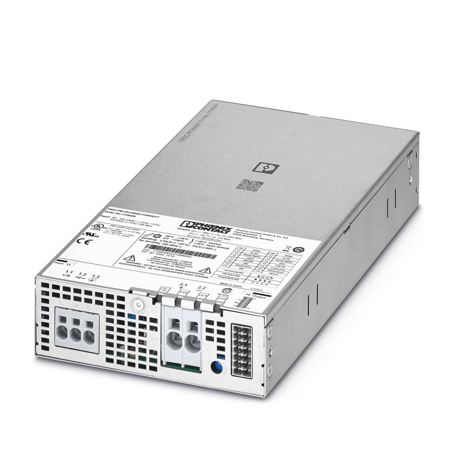
Primary-switched power supply unit, TRIO POWER, Push-in connection, CAN bus, Panel mounting, input: 1-phase, output: 48 V DC / 31.25 A, adjustable from 45 V DC ... 55 V DC
Product details
| AC operation | |
| Supply system configuration | Star network (TN, TT, IT (PE)) |
| Nominal input voltage range | 100 V AC ... 240 V AC |
| Input voltage range | 100 V AC ... 240 V AC -15 % ... +10 % |
| 100 V AC ... 240 V AC ±10 % (UL) | |
| Derating | 85 V AC ... 90 V AC (≤ 1350 W) |
| 90 V AC ... 180 V AC (≤ 1500 W) | |
| Electric strength, max. | 300 V AC 1 s |
| Typical national grid voltage | 120 V AC |
| 230 V AC | |
| Voltage type of supply voltage | AC |
| Inrush current | < 10 A (115 V AC, 25 °C) |
| < 15 A (230 V AC, 25 °C) | |
| Inrush current integral (I2t) | < 0.417 A2s |
| Frequency range (fN) | 50 Hz ... 60 Hz ±5 % |
| Mains buffering time | typ. 16 ms (120 V AC@80% load) |
| typ. 16 ms (230 V AC@80% load) | |
| Buffer time | typ. 18 ms (120 V AC@80% load) |
| typ. 18 ms (230 V AC@80% load) | |
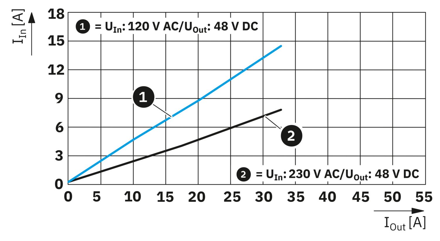
| Current consumption | 13.7 A (120 V AC) |
| 17.6 A (85 V AC) | |
| 6.1 A (264 V AC) | |
| 7 A (230 V AC) | |
| max. 18 A (UL) | |
| Protective circuit | Transient protection |
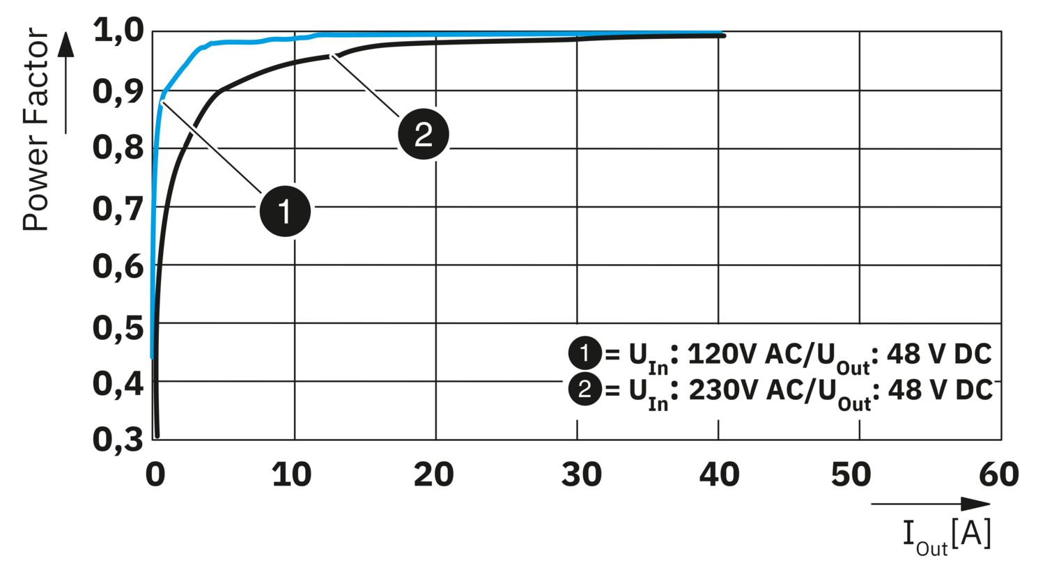
| Power factor (cos phi) | 0.99 (230 V AC) |
| Device mains fuse | 25 A internal (device protection) |
| Discharge current to PE | < 2 mA |
| DC operation | |
| Input voltage range | 250 V DC ... 340 V DC -15 % ... +10 % |
| Current consumption | 6.4 A (250 V DC) |
| 4.2 A (380 V DC) | |
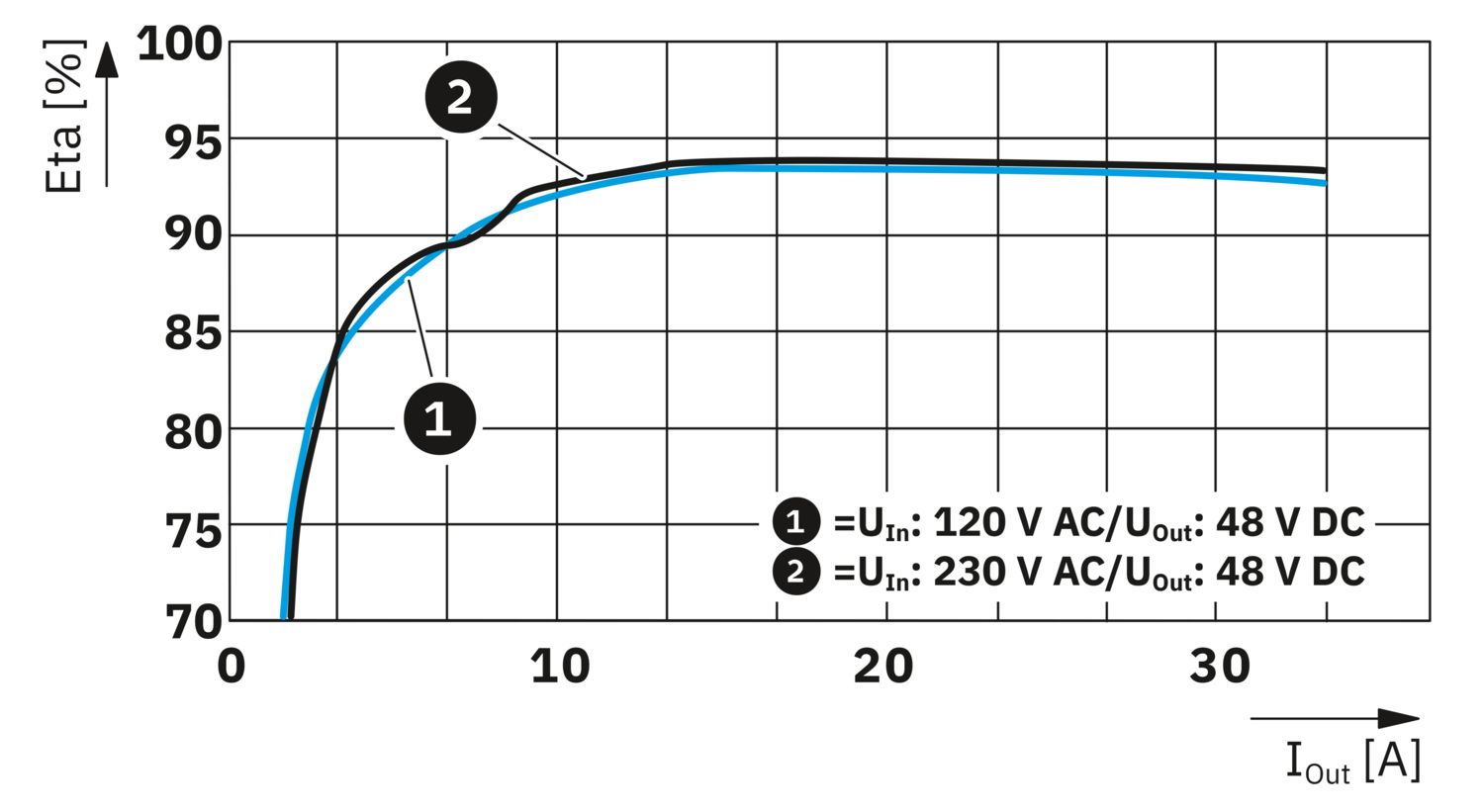
| Efficiency | typ. 92 % (120 V AC) |
| typ. 94 % (230 V AC) | |
| Nominal output voltage | 48 V DC |
| Setting range of the output voltage (USet) | 45 V DC ... 55 V DC (> 48 V DC, constant capacity restricted) |
| Nominal output current (IN) | 31.25 A |
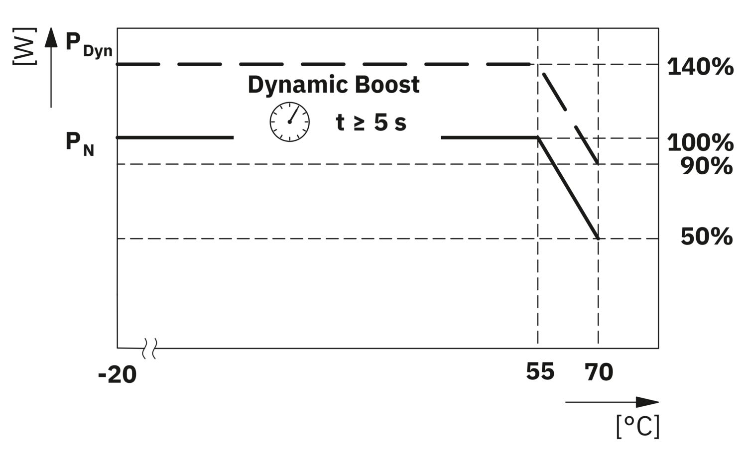
| Dynamic Boost (IDyn.Boost) | max. 40.63 A (5 s) |
| Short-circuit-proof | yes |
| No-load proof | yes |
| Derating | 55 °C ... 70 °C (3.33 %/K) |
| Crest factor | typ. 1.484 (120 V AC) |
| typ. 1.528 (230 V AC) | |
| Output power (PN) | 1500 W |
| Output power (PDyn. Boost) | max. 1950 W (5 s) |
| Connection in parallel | yes, for increased efficiency and redundancy |
| max. 4 | |
| Connection in series | yes, for increased output voltage (observe SELV limit) |
| max. 2 | |
| Feedback voltage resistance | ≤ 63 V DC |
| Protection against overvoltage at the output (OVP) | ≤ 63 V DC |
| Residual ripple | typ. 250 mVPP |
| Control deviation | < 0.5 % (change in load, static 10 % ... 90 %) |
| < 5 % (change in load, dynamic 10 % ... 90 %) | |
| < 0.5 % (change in input voltage ±10 %) | |
| Rise time | ≤ 100 ms (UOut = 10 % ... 90 %) |
| Minimum no-load power dissipation | < 15 W (120 V AC) |
| Maximum no-load power dissipation | < 10 W (230 V AC) |
| Minimum nominal load power dissipation | < 130 W (120 V AC) |
| Power loss nominal load max. | < 90 W (230 V AC) |
| Integrated fuse protection | no |
| Input | |
| Position | 1.x |
| Connection technology | |
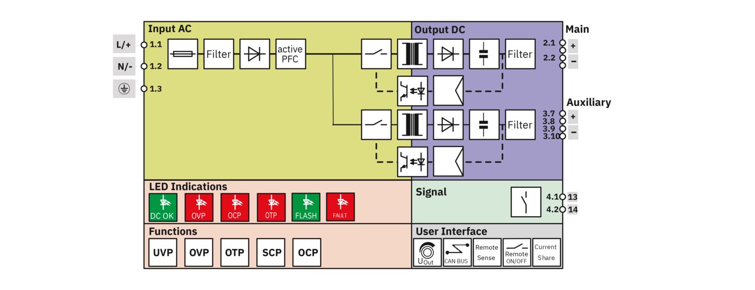
| Position marking | 1.1 (L/+), 1.2 (N/-), 1.3 () |
| Conductor connection | |
| Connection method | Push-in connection |
| rigid | 0.2 mm² ... 10 mm² |
| 2.5 mm² (recommended) | |
| flexible | 0.2 mm² ... 6 mm² |
| 2.5 mm² (recommended) | |
| flexible with ferrule without plastic sleeve | 0.25 mm² ... 6 mm² |
| 2.5 mm² (recommended) | |
| flexible with ferrule with plastic sleeve | 0.25 mm² ... 6 mm² |
| 2.5 mm² (recommended) | |
| AWG | 24 ... 8 (Cu) |
| 14 (recommended) | |
| Stripping length | 15 mm (Rigid/flexible/ferrule) |
| Output | |
| Position | 2.x |
| Connection technology | |
| Position marking | 2.1 (+), 2.2 (-) |
| Conductor connection | |
| Connection method | Push-in connection |
| rigid | 0.75 mm² ... 16 mm² |
| 6 mm² (recommended) | |
| flexible | 0.75 mm² ... 16 mm² |
| 6 mm² (recommended) | |
| flexible with ferrule without plastic sleeve | 0.75 mm² ... 16 mm² |
| 6 mm² (recommended) | |
| flexible with ferrule with plastic sleeve | 0.75 mm² ... 10 mm² |
| 6 mm² (recommended) | |
| AWG | 20 ... 4 (Cu) |
| 6 (recommended) | |
| Stripping length | 18 mm (Rigid/flexible/ferrule) |
| Conductor connection | |
| Connection method | Connector |
| Signal, communication | |
| Position | 3.x |
| Connection technology | |
| Position marking | 3.1 - 3.14 |
| Conductor connection | |
| Connection method | Push-in connection |
| rigid | 0.2 mm² ... 1.5 mm² |
| 0.5 mm² (recommended) | |
| flexible | 0.2 mm² ... 1.5 mm² |
| 0.5 mm² (recommended) | |
| flexible with ferrule without plastic sleeve | 0.25 mm² ... 1.5 mm² (Cu) |
| 0.5 mm² (recommended) | |
| flexible with ferrule with plastic sleeve | 0.14 mm² ... 0.75 mm² |
| 0.5 mm² (recommended) | |
| AWG | 24 ... 16 (Cu) |
| 20 (recommended) | |
| Stripping length | 10 mm (Rigid/flexible/ferrule) |
| CAN-Bus | |
| Interface | CAN bus |
| Number of interfaces | 1 |
| Connection method | Push-in connection |
| Supported protocols | CAN 2.0A, CAN 2.0B |
| Transmission physics | wired |
| Topology | Daisy Chain |
| Transmission speed | 250 kbps |
| Transmission length | max. 20 m |
| Termination resistor | 120 Ω (Terminating the end device) |
| Number of bus devices | max. 16 |
| LED signaling | |
| Types of signaling | DC OK LED - signal state operation (UN = 48 V DC, IOut = IN) |
| Function | Visualization of the operating state of the DC output voltage (DC OK) |
| Color | Red, green (multicolor LED) |
| LED off | Supply voltage input AC not present (Off) |
| LED on (green), DC OK | UOutSet x 0.95 < UOut < UOutSet x 1.05 and IOut < IN (On (green), DC OK) |
| LED on (flashing green) | UOutSet x 1.05 < UOut < UOutSet x 1.1 orUOutSet x 0.9 < UOut < UOutSet x 0.95 orIN < IOut < IN x 1.1 (On (flashing green)) |
| LED on (red) | UOutSet x 0.9 > UOut orUOutSet x 1.1 < UOut orIOut > IN x 1.1, continuously for 6 s (On (red)) |
| LED signaling | |
| Types of signaling | LED OVP - signal state operation (UN = 48 V DC, IOut = IN) |
| Function | Visualization of the surge protection operating state (OVP) |
| Color | Red, green (multicolor LED) |
| LED off | Supply voltage input AC not present (Off) |
| LED on (green) | UOUT < UOutSet x 1.1 (on (green)) |
| LED on (flashing green) | UOutSet x 1.1 < UOut < OVP (on (flashing green)) |
| LED on (red) | UOut > OVP (on (red)) |
| LED signaling | |
| Types of signaling | LED OCP - signal state operation (UN = 48 V DC, IOut = IN) |
| Function | Visualization of the overcurrent protection operating state (OCP) |
| Color | Red, green (multicolor LED) |
| LED off | Supply voltage input AC not present (Off) |
| LED on (green) | IOut < IN x 1.1 (on (green)) |
| LED on (flashing green) | IN x 1.1 < IOut < IN x 1.3 (on (flashing green)) |
| LED on (red) | IOut > IN x 1.3 continuously for 6 s (on (red)) |
| LED signaling | |
| Types of signaling | LED OTP - signal state operation (UN = 48 V DC, IOut = IN) |
| Function | Visualization of the overtemperature protection operating state (OTP) |
| Color | Red, green (multicolor LED) |
| LED off | Supply voltage input AC not present |
| LED on (green) | TAmb < OTP - 10 °C (on (green)) |
| LED on (flashing green) | OTP - 10 °C < TAmb < OTP (on (flashing green)) |
| LED on (red) | OTP < TAmb (on (red)) |
| LED signaling | |
| Types of signaling | LED FAN - signal state operation (UN = 48 V DC, IOut = IN) |
| Function | Visualization of the operating state of the fan (in operation or malfunction) |
| Color | Red, green (multicolor LED) |
| LED on (green) | FAN normal operation (on (4 x LED green)) |
| LED on (red) | FAN failure (on (4 x LED red)) |
| LED signaling | |
| Types of signaling | LED SCP - signal state operation (UN = 48 V DC, IOut = IN) |
| Function | Visualization of the short-circuit protection operating state (SCP) |
| Color | Red, green (multicolor LED) |
| LED on (flowing red) | Short circuit (on (4 x LED red continuous)) |
| LED signaling | |
| Types of signaling | LED Charging Mode – signal state operation (UN = 48 V DC, IOut = IN) |
| Function | Visualization of the charging mode |
| Color | Red, green (multicolor LED) |
| LEDs on (green flashing) | Charging mode activated (on (4 x LED green flashing)) |
| Signal output DC OK | |
| Position | 3.x |
| Type of signaling | DC OK switch contact - signal state operation (UN = 48 V DC, IOut = IN) |
| Position marking | 3.1 (13), 3.2 (14) |
| Function | Operating state forwarding |
| Switch contact (floating) | Optocoupler |
| Switching voltage | max. 30 V DC (SELV) |
| Current carrying capacity | max. 10 mA |
| State condition (Contact closed) | UOut > 0.75 * UOutSet (Contact closed) |
| State condition (Contact open) | UOut < 0.75 * UOutSet (Contact open) |
| Number of phases | 1 |
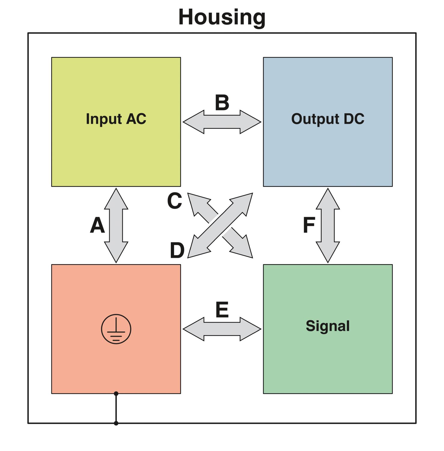
| Insulation voltage input/output | 4 kV AC (type test) |
| 1.5 kV AC (routine test) |
| Product type | Power supply |
| Product family | TRIO POWER |
| Scope of supply | Power supply unit TRIO-PM/.../PT, 1 pc. |
| PCB connector, 2 x 7-pos., 1 pc. | |
| 1 set of universal wall adapters UWA 20/13 | |
| MTBF (IEC 61709, SN 29500) | > 600000 h (25 °C) |
| > 250000 h (40 °C) | |
| > 100000 h (55 °C) | |
| Insulation characteristics | |
| Protection class | I |
| Degree of pollution | 2 |
| Life expectancy (electrolytic capacitors) | |
| Temperature | 25 °C |
| Additional text | 8 years |
| Item dimensions | |
| Width | 128 mm |
| Height | 41 mm |
| Depth | 222 mm |
| Mounting type | Panel mounting |
| Assembly note | Side mounting: 2x M4 screws - installation depth < 4 mm Back mounting: 4x M4 screws - installation depth < 3 mm Mounting with Assembly adapter UWA 20/13 (Item no. 1697537) |
| Flammability rating according to UL 94 | V0 (Housing, terminal blocks) |
| Hood version | Aluminum (AlMg3) |
| Side element version | Aluminum |
| Ambient conditions | |
| Degree of protection | IP20 |
| Ambient temperature (operation) | -20 °C ... 70 °C (> 55 °C Derating: 2.5 %/K) |
| Ambient temperature (storage/transport) | -40 °C ... 85 °C |
| Ambient temperature (start-up type tested) | -40 °C |
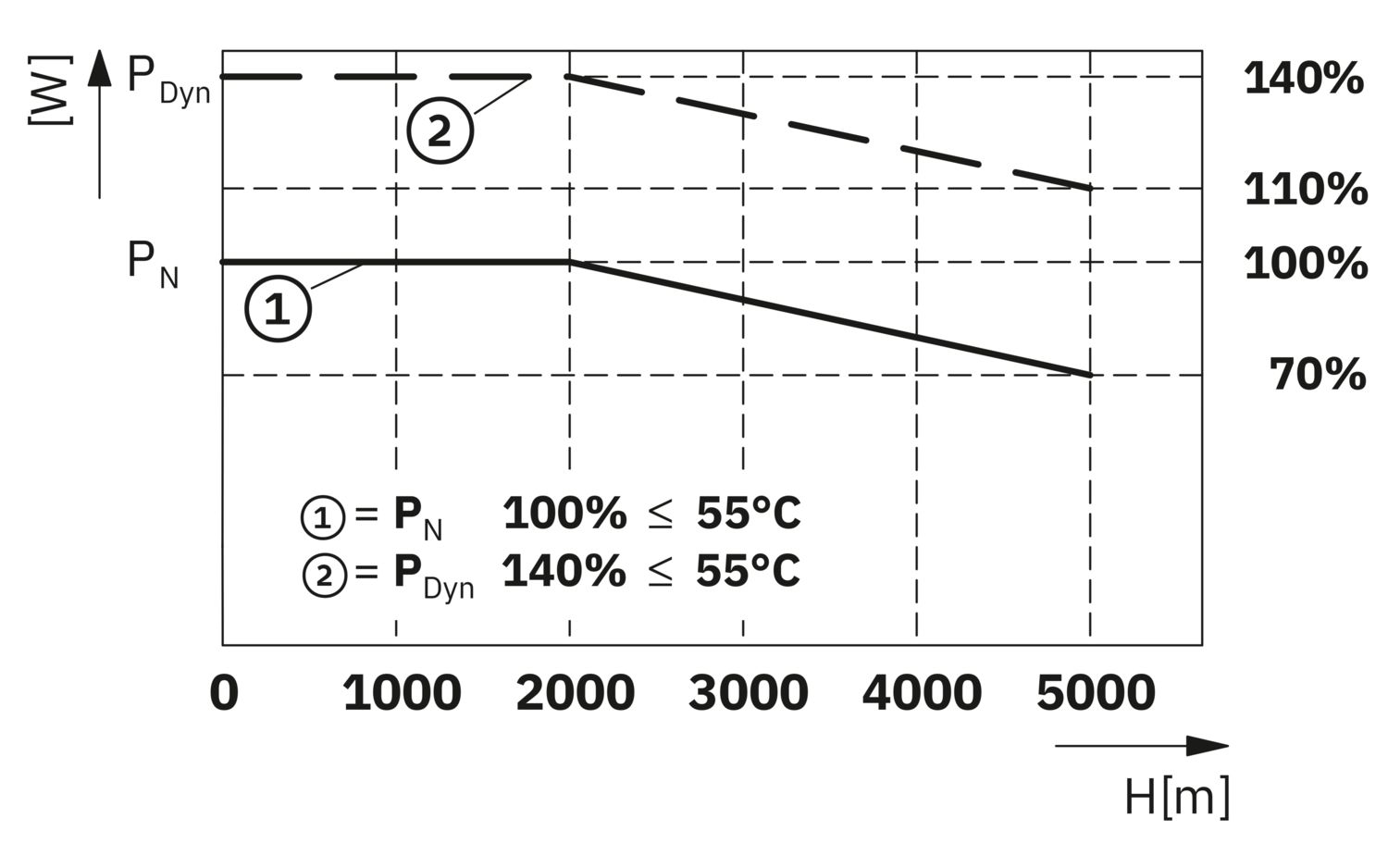
| Maximum altitude (EN 61558-2-16) | ≤ 5000 m |
| Maximum altitude (Output power derating) | > 2000 m (Derating: 10%/1000 m) |
| Max. permissible relative humidity (operation) | ≤ 95 % (at 25 °C, non-condensing) |
| Shock (operation) | 11 ms, 15g, per spatial direction (IEC 60068-2-27) |
| Vibration (operation) | 10 Hz ... 18.2 Hz, amplitude ±0.75 mm (IEC 60068-2-6) |
| 18.2 Hz ... 150 Hz, 1g, 90 min. | |
| Overvoltage category | |
| EN 61010-1 | II (≤ 5000 m) |
| Overvoltage category | |
| EN 61010-2-201 | II (≤ 5000 m) |
| Safety of power supply units up to 1100 V (insulation distances) | |
| Standard designation | Safety of power supply units up to 1100 V (insulation distances) |
| Standards/specifications | DIN EN 61558-2-16 |
| Electrical safety | |
| Standard designation | Electrical safety |
| Standards/specifications | IEC 61010-2-201 (SELV) |
| Safety for measurement, control, and laboratory equipment | |
| Standard designation | Safety for equipment for measurement, control, and laboratory use |
| Standards/specifications | IEC 61010-1 |
| Protective extra-low voltage | |
| Standard designation | Protective extra-low voltage |
| Standards/specifications | IEC 61010-1 (SELV) |
| IEC 61010-2-201 (PELV) | |
| Safe isolation | |
| Standard designation | Safe isolation |
| Standards/specifications | IEC 61010-2-201 |
| Limitation of harmonic line currents | |
| Standard designation | Limitation of harmonic line currents |
| Standards/specifications | EN 61000-3-2 |
| Mains variation/undervoltage | |
| Standard designation | Mains variation/undervoltage |
| Standards/specifications | SEMI F47 - 0706 |
| UL | |
| Identification | UL/C-UL Listed UL 61010-1 |
| UL | |
| Identification | UL/C-UL Listed UL 61010-2-201 |
| UL | |
| Identification | UL/C-UL Approved UL 62368-1 |
| Electromagnetic compatibility | Conformance with EMC Directive 2014/30/EU |
| Low Voltage Directive | Conformance with Low Voltage Directive 2014/35/EC |
| Interference emission | Interference emission in accordance with EN 61000-6-3 (residential and commercial) and EN 61000-6-4 (industrial) |
| Noise immunity | Immunity in accordance with EN 61000-6-1 (residential), EN 61000-6-2 (industrial) |
| Conducted noise emission | |
| Standards/regulations | EN 55016 |
| EN 61000-6-3 (Class B) | |
| Noise emission | |
| Standards/regulations | EN 55016 |
| EN 61000-6-3 (Class B) | |
| Harmonic currents | |
| Standards/regulations | EN 61000-3-2 |
| EN 61000-3-2 (Class A) | |
| Frequency range | 0 kHz ... 2 kHz |
| Flicker | |
| Standards/regulations | EN 61000-3-3 |
| EN 61000-3-3 | |
| Electrostatic discharge | |
| Standards/regulations | EN 61000-4-2 |
| Electrostatic discharge | |
| Contact discharge | 6 kV (Test Level 3) |
| Discharge in air | 8 kV (Test Level 3) |
| Comments | Criterion B |
| Electromagnetic HF field | |
| Standards/regulations | EN 61000-4-3 |
| Electromagnetic HF field | |
| Frequency range | 80 MHz ... 1 GHz |
| Test field strength | 10 V/m (Test Level 3) |
| Frequency range | 1 GHz ... 6 GHz |
| Test field strength | 10 V/m (Test Level 3) |
| Comments | Criterion A |
| Fast transients (burst) | |
| Standards/regulations | EN 61000-4-4 |
| Fast transients (burst) | |
| Input | asymmetrical 2 kV (Test Level 3) |
| Output | asymmetrical 2 kV (Test Level 3) |
| Signal | asymmetrical 1 kV (Test Level 3) |
| Comments | Criterion B |
| Surge voltage load (surge) | |
| Standards/regulations | EN 61000-4-5 |
| Surge voltage load (surge) | |
| Input | symmetrical 2 kV (Test Level 4) |
| asymmetrical 4 kV (Test Level 4) | |
| Output | symmetrical 0.5 kV (Test Level 2) |
| asymmetrical 1 kV (Test Level 2) | |
| Signal | asymmetrical 1 kV (Test Level 2) |
| Comments | Criterion B |
| Conducted interference | |
| Standards/regulations | EN 61000-4-6 |
| Conducted interference | |
| Input/output/signal | asymmetrical |
| Frequency range | 0.15 MHz ... 80 MHz |
| Comments | Criterion A |
| Voltage | 10 V (Test Level 3) |
| Voltage dips | |
| Standards/regulations | EN 61000-4-11 |
| Voltage | 230 V AC |
| Frequency | 50 Hz |
| Voltage dip | 70 % |
| Number of periods | 25 periods |
| Additional text | Class 3 |
| Comments | Criterion B |
| Voltage dip | 40 % |
| Number of periods | 10 periods |
| Additional text | Class 3 |
| Comments | Criterion B |
| Voltage dip | 0 % |
| Number of periods | 1 period |
| Additional text | Class 3 |
| Comments | Criterion B |
| Criteria | |
| Criterion A | Normal operating behavior within the specified limits. |
| Criterion B | Temporary impairment to operational behavior that is corrected by the device itself. |
| Criterion C | Temporary adverse effects on the operating behavior, which the device corrects automatically or which can be restored by actuating the operating elements. |
| Item number | 1739009 |
| Packing unit | 1 pc |
| Minimum order quantity | 1 pc |
| Sales key | ***** |
| Product key | CMHW14 |
| GTIN | 4067923302631 |
| Weight per piece (including packing) | 1,914 g |
| Weight per piece (excluding packing) | 1,900 g |
| Country of origin | CN |
ECLASS
| ECLASS-13.0 | 27040701 |
| ECLASS-15.0 | 27040701 |
ETIM
| ETIM 9.0 | EC002540 |
| EU RoHS | |
| Fulfills EU RoHS substance requirements | Yes |
| Exemption | 6(c), 7(c)-I |
| China RoHS | |
| Environment friendly use period (EFUP) |
EFUP-25
An article-related China RoHS declaration table can be found in the download area for the respective article under "Manufacturer declaration". For all articles with EFUP-E, no China RoHS declaration table issued and required.
|
| EU REACH SVHC | |
| REACH candidate substance (CAS No.) | Lead (CAS: 7439-92-1) |
Compatible products
-
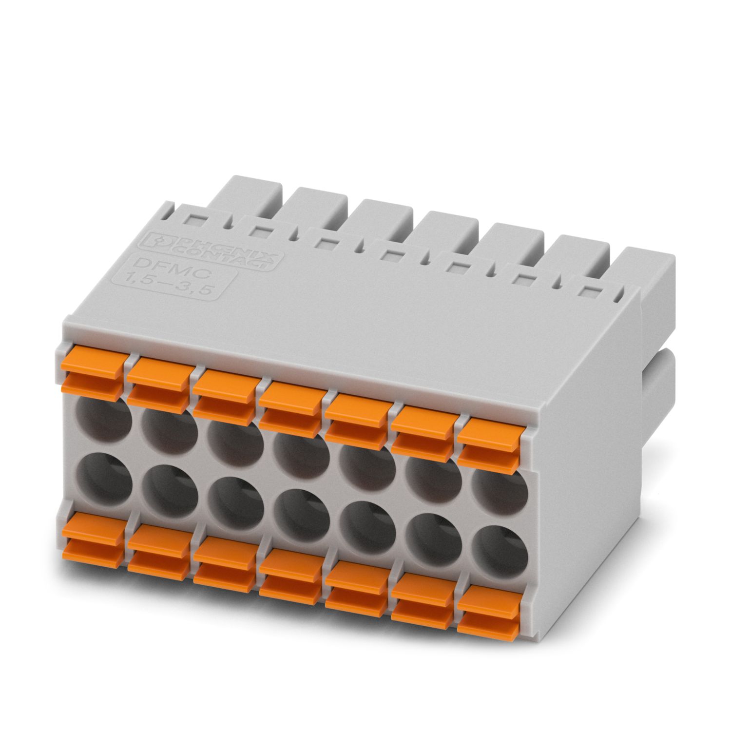
DFMC 1,5/ 7-ST-3,5 GY - PCB connector 1776292
-
UWA 20/13 - Mounting adapter 1697537
-
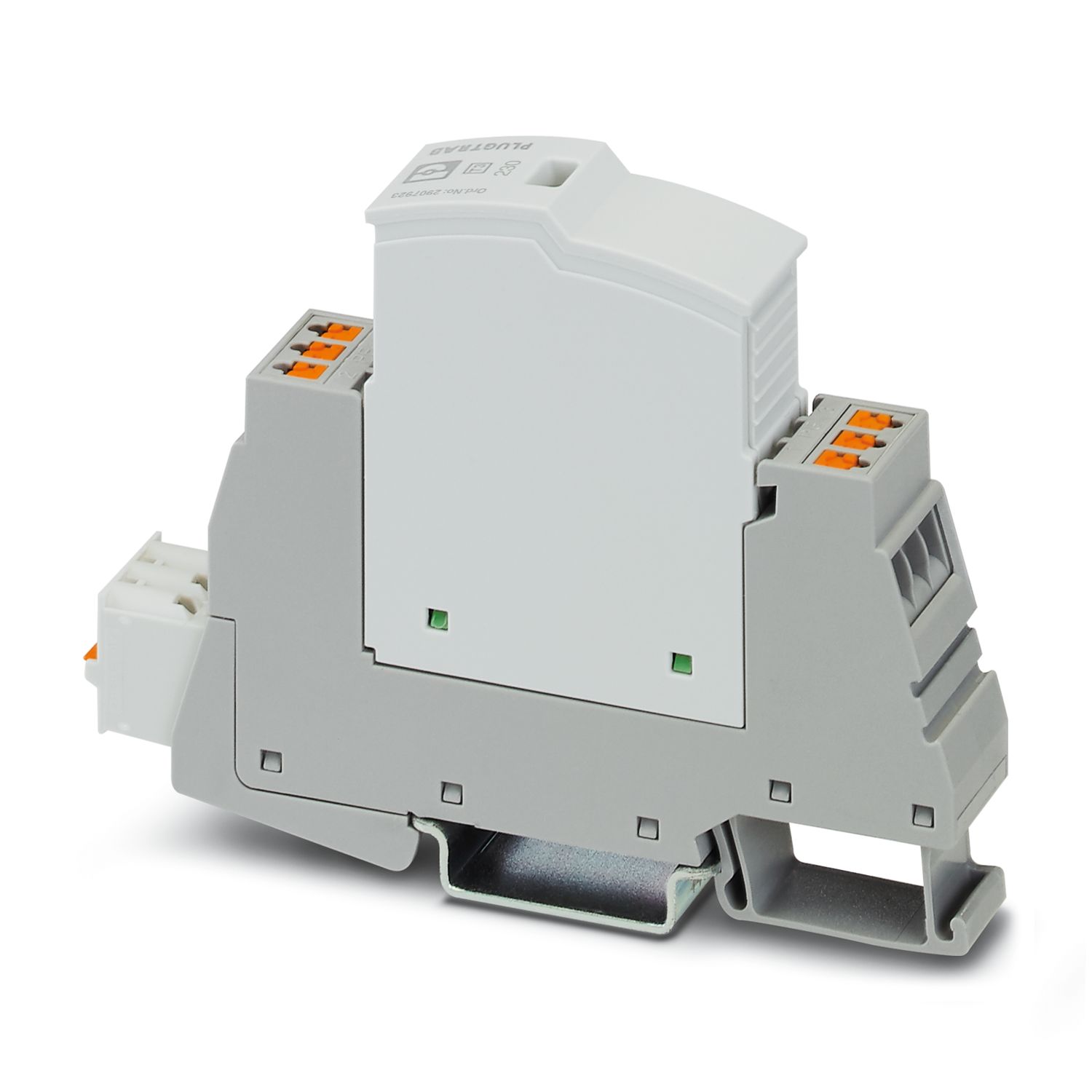
PLT-SEC-T3-230-FM-PT - Type 3 surge protection device 2907928
-
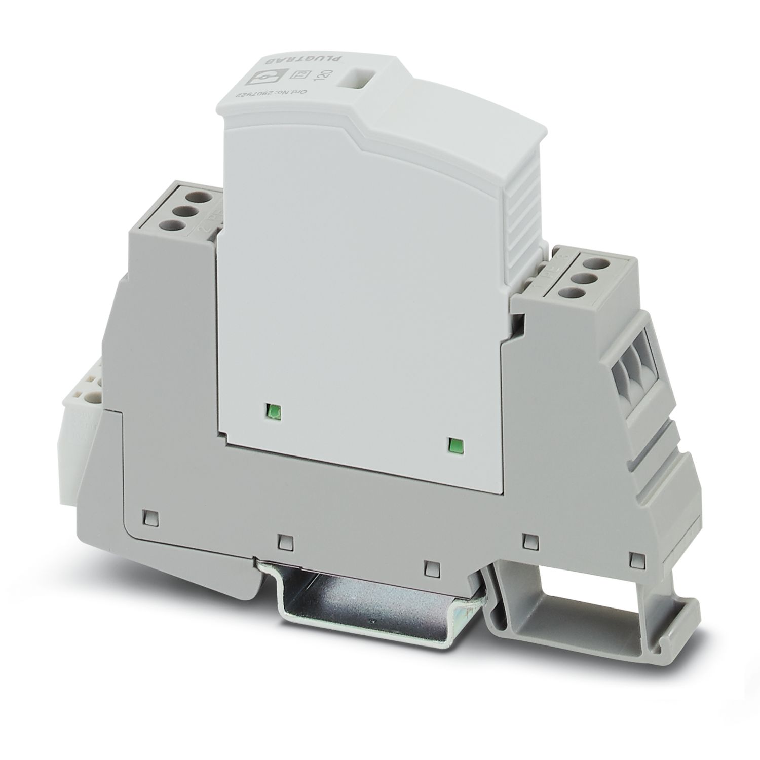
PLT-SEC-T3-120-FM-UT - Type 3 surge protection device 2907918
-
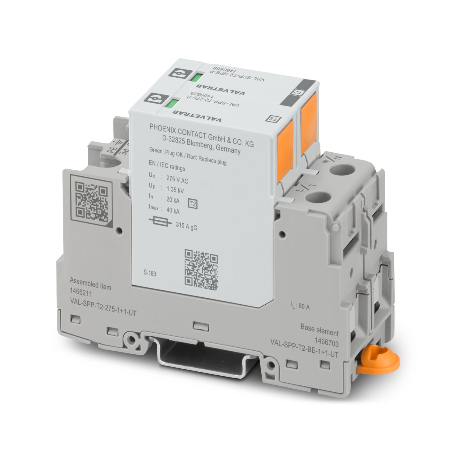
VAL-SPP-T2-275-1+1-UT - Type 2 surge arrester 1466211
-
VAL-US-120/40/1+1-FM - Surge protection device 2910349
-
PTCB E1 48DC/1-6A NO - Electronic circuit breaker 1471917
-
TMC 72D 15A - Miniature Circuit Breaker 1020072

Your advantages
High power density and high efficiency with a compact design
Customized use through flexible panel mounting options
Robust and reliable due to integrated protective functions
Easy power increase with parallel connection with integrated O-ring diode
Smart diagnostics with comprehensive monitoring via LED signaling, CAN bus interface, and EOL (End Of Life) reminder
PHOENIX CONTACT (Ireland) Ltd
C6 The Exchange, Calmount Park, Ballymount, Dublin 12, D12 XE18, Ireland