STEP POWER power supplies for distribution boards
The STEP POWER power supply range was developed especially for building automation. The low idling losses and high degree of efficiency ensure maximum energy efficiency. They allow flexible use and can be snapped onto the DIN rail or screwed onto an even surface.
STEP-PS/48AC/24DC/0.5
-
Power supply
2868716
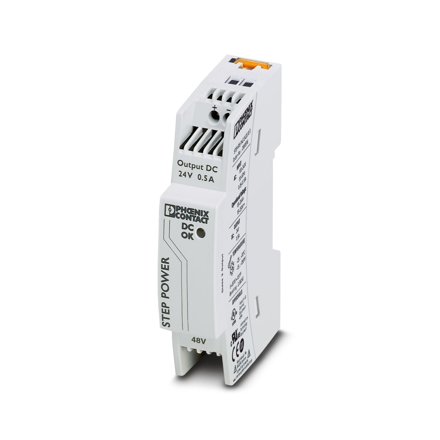
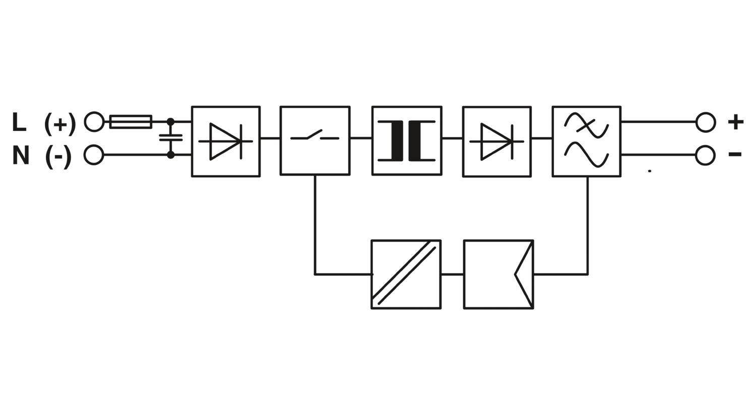
Primary-switched STEP POWER power supply for DIN rail and direct mounting, input: 1-phase, output: 24 V DC/0.5 A
Product details
AC operation | |
Nominal input voltage range | 48 V AC |
Input voltage range | 43 V AC ... 52 V AC |
Voltage type of supply voltage | AC |
Inrush current | < 10 A (typical) |
Inrush current integral (I2t) | < 0.1 A2s |
AC frequency range | 45 Hz ... 65 Hz |
Frequency range DC | 0 Hz |
Mains buffering time | typ. 15 ms (48 V AC) |
typ. 20 ms (52 V AC) | |
Current consumption | 0.5 A (43 V AC) |
0.45 A (48 V AC) | |
Nominal power consumption | 21 VA |
Power factor (cos phi) | 0.7 |
Typical response time | < 0.5 s |
Input fuse | 1.25 A (slow-blow, internal) |
Recommended breaker for input protection | 6 A ... 16 A (Characteristics B, C, D, K) |
DC operation | |
Input voltage range | 95 V DC ... 250 V DC |
Voltage type of supply voltage | DC |
Efficiency | > 81 % (for 48 V AC and nominal values) |
Output characteristic | U/I |
Nominal output voltage | 24 V DC |
Output current Imax | 1 A |
Nominal output current (IN) | 0.5 A (-25 °C ... 55 °C) |
0.55 A (-25 °C ... 40 °C permanent) | |
Derating | 55 °C ... 70 °C (2.5 %/K) |
Feedback voltage resistance | ≤ 35 V DC |
Protection against overvoltage at the output (OVP) | < 35 V DC |
Control deviation | < 1 % (change in load, static 10 % ... 90 %) |
< 2 % (change in load, dynamic 10 % ... 90 %) | |
< 0.1 % (change in input voltage ±10 %) | |
Residual ripple | < 30 mVPP (20 MHz) |
Output power | 12 W |
Peak switching voltages nominal load | < 20 mVPP (20 MHz) |
Maximum no-load power dissipation | < 0.3 W |
Power loss nominal load max. | < 3.4 W |
Connection in parallel | yes, for redundancy and increased capacity |
Connection in series | yes |
Input | |
Connection method | Screw connection |
Conductor cross section, rigid min. | 0.2 mm² |
Conductor cross section, rigid max. | 2.5 mm² |
Conductor cross section flexible min. | 0.2 mm² |
Conductor cross section flexible max. | 2.5 mm² |
Conductor cross section AWG min. | 24 |
Conductor cross section AWG max. | 12 |
Stripping length | 6.5 mm |
Screw thread | M3 |
Tightening torque, min | 0.5 Nm |
Tightening torque max | 0.6 Nm |
Output | |
Connection method | Screw connection |
Conductor cross section, rigid min. | 0.2 mm² |
Conductor cross section, rigid max. | 2.5 mm² |
Conductor cross section flexible min. | 0.2 mm² |
Conductor cross section flexible max. | 2.5 mm² |
Conductor cross section AWG min. | 24 |
Conductor cross section AWG max. | 12 |
Stripping length | 6.5 mm |
Screw thread | M3 |
Tightening torque, min | 0.5 Nm |
Tightening torque max | 0.6 Nm |
Types of signaling | LED |
Operating voltage display | Green LED |
Signal output: LED status indicator | |
Status display | "DC OK" LED green |
Note on status display | UOUT > 21.5 V: LED lights up |
Number of phases | 1 |
Insulation voltage input/output | 4 kV AC (type test) |
3.75 kV AC (routine test) | |
4 kV AC (type test) |
Product type | Power supply |
Product family | STEP POWER |
MTBF (IEC 61709, SN 29500) | > 1860000 h (40 °C) |
Insulation characteristics | |
Protection class | II (in closed control cabinet) |
Overvoltage category | III |
Degree of pollution | 2 |
Width | 18 mm |
Height | 90 mm |
Depth | 61 mm |
Horizontal pitch | 1 Div. |
Installation dimensions | |
Installation distance right/left | 0 mm / 0 mm |
Installation distance top/bottom | 30 mm / 30 mm |
Mounting type | DIN rail mounting |
Assembly note | alignable: 0 mm horizontally, 30 mm vertically |
Mounting position | horizontal DIN rail NS 35, EN 60715 |
With protective coating | no |
Housing material | Plastic |
Housing material | PC |
Foot latch material | POM (Polyoxymethylene) |
Ambient conditions | |
Degree of protection | IP20 |
Ambient temperature (operation) | -25 °C ... 70 °C (> 55 °C Derating: 2.5 %/K) |
Ambient temperature (storage/transport) | -40 °C ... 85 °C |
Ambient temperature (start-up type tested) | -40 °C |
Climatic class | 3K3 (in acc. with EN 60721) |
Max. permissible relative humidity (operation) | ≤ 95 % (at 25 °C, non-condensing) |
Shock | 18 ms, 30g, in each space direction (according to IEC 60068-2-27) |
Vibration (operation) | < 15 Hz, amplitude ±2.5 mm (according to IEC 60068-2-6) |
15 Hz ... 150 Hz, 2.3g, 90 min. |
Rail applications | EN 50121-4 |
Standard – Electronic equipment for use in electrical power installations and their assembly into electrical power installations | EN 50178/VDE 0160 (PELV) |
Standard – Limitation of mains harmonic currents | EN 61000-3-2 |
Standard - Electrical safety | IEC 62368-1 (SELV) |
Standard – Protection against shock currents, basic requirements for protective separation in electrical equipment | EN 50178 |
Standard – Safety extra-low voltage | IEC 62368-1 (SELV) und EN 60204-1 (PELV) |
Standard - Safe isolation | DIN VDE 0100-410 |
Standard - Safety of transformers | EN 61558-2-16 |
UL approvals | UL/C-UL listed UL 508 |
UL/C-UL Recognized UL 60950-1 | |
NEC Class 2 as per UL 1310 | |
Conformity/Approvals | |
SIL in accordance with IEC 61508 | 0 |
Electromagnetic compatibility | Conformance with EMC Directive 2014/30/EU |
Low Voltage Directive | Conformance with Low Voltage Directive 2014/35/EC |
EMC requirements for noise emission | EN 61000-6-3 |
EN 61000-6-4 | |
EMC requirements for noise immunity | EN 61000-6-1 |
EN 61000-6-2 | |
Electrostatic discharge | |
Standards/regulations | EN 61000-4-2 |
Electrostatic discharge | |
Contact discharge | 6 kV (Test Level 3) |
Discharge in air | 8 kV (Test Level 3) |
Comments | Criterion A |
Electromagnetic HF field | |
Standards/regulations | EN 61000-4-3 |
Electromagnetic HF field | |
Frequency range | 80 MHz ... 3 GHz |
Test field strength | 10 V/m (Test Level 3) |
Comments | Criterion A |
Fast transients (burst) | |
Standards/regulations | EN 61000-4-4 |
Fast transients (burst) | |
Input | 2 kV (Test Level 3 - asymmetrical) |
Output | 2 kV (Test Level 3 - asymmetrical) |
Comments | Criterion A |
Surge voltage load (surge) | |
Standards/regulations | EN 61000-4-5 |
Surge voltage load (surge) | |
Input | 1 kV (Test Level 2 - symmetrical) |
2 kV (Test Level 3 - asymmetrical) | |
Output | 0.5 kV (Test Level 1 - symmetrical) |
1 kV (Test Level 2 - asymmetrical) | |
Comments | Criterion A |
Conducted interference | |
Standards/regulations | EN 61000-4-6 |
Conducted interference | |
Input/Output | Test Level 3 |
Frequency range | 150 kHz ... 80 MHz |
Comments | Criterion A |
Voltage | 10 V |
Emitted interference | |
Standards/regulations | EN 61000-6-3 |
Radio interference voltage in acc. with EN 55011 | EN 55011 (EN 55022) Class B, area of application: Industry and residential |
Emitted radio interference in acc. with EN 55011 | EN 55011 (EN 55022) Class B, area of application: Industry and residential |
Item number | 2868716 |
Packing unit | 1 pc |
Minimum order quantity | 1 pc |
Sales key | CM |
Product key | CMPS93 |
Catalog page | Page 279 (C-4-2019) |
GTIN | 4046356576789 |
Weight per piece (including packing) | 87.87 g |
Weight per piece (excluding packing) | 87 g |
Customs tariff number | 85044082 |
Country of origin | DE |
ECLASS
ECLASS-13.0 | 27040701 |
ETIM
ETIM 9.0 | EC002540 |
UNSPSC
UNSPSC 21.0 | 39121000 |
EU RoHS | |
Fulfills EU RoHS substance requirements | Yes |
Exemption | 6(c), 7(c)-I |
China RoHS | |
Environment friendly use period (EFUP) |
EFUP-25
An article-related China RoHS declaration table can be found in the download area for the respective article under "Manufacturer declaration". For all articles with EFUP-E, no China RoHS declaration table issued and required.
|
EU REACH SVHC | |
REACH candidate substance (CAS No.) | Lead (CAS: 7439-92-1) |
SCIP | 528c7c79-8e88-4706-94a9-07cce9f28105 |
EF3.0 Climate Change | |
CO2e kg | 3.273 kg CO2e |
Compatible products
Your advantages
Flexible mounting by simply snapping onto the DIN rail or screwing onto a level surface
Reliable power supply thanks to high MTBF (mean time between failures) of more than 500,000 hours and U/I characteristic curve
Energy savings thanks to maximum energy efficiency and incredibly low idling losses
PHOENIX CONTACT (Ireland) Ltd
C6 The Exchange, Calmount Park, Ballymount, Dublin 12, D12 XE18, Ireland