
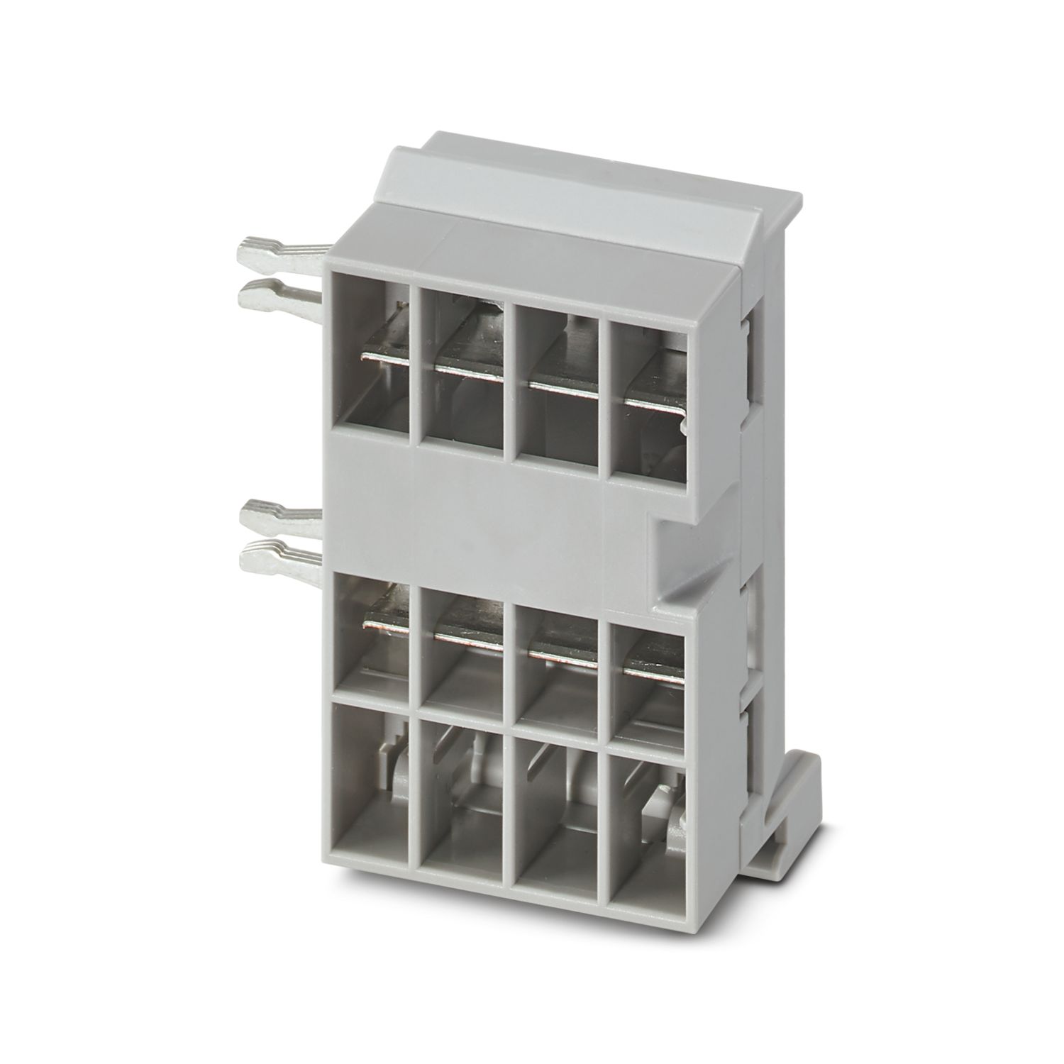
CAPAROC PD 0V
-
Potential distributors
1110987
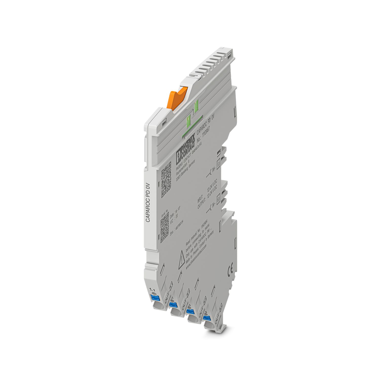


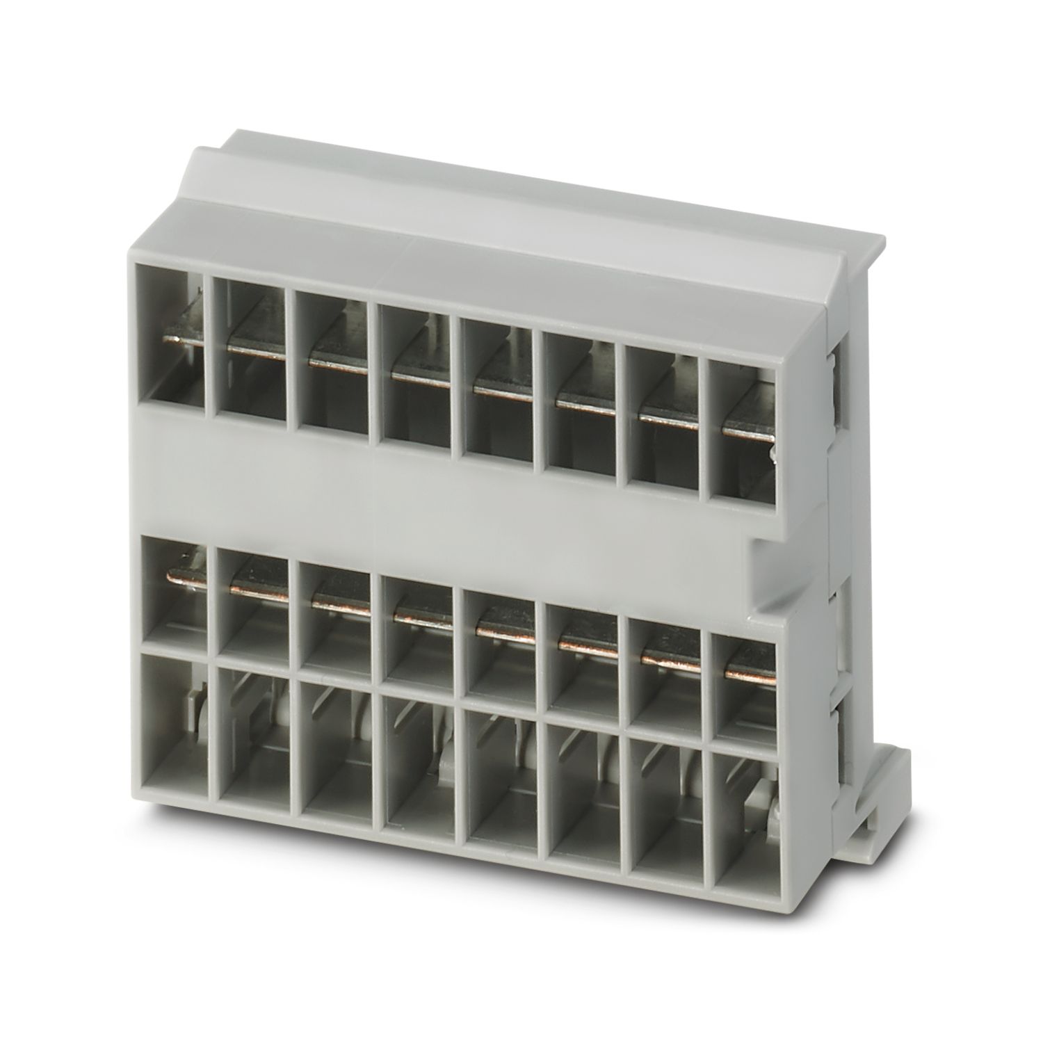
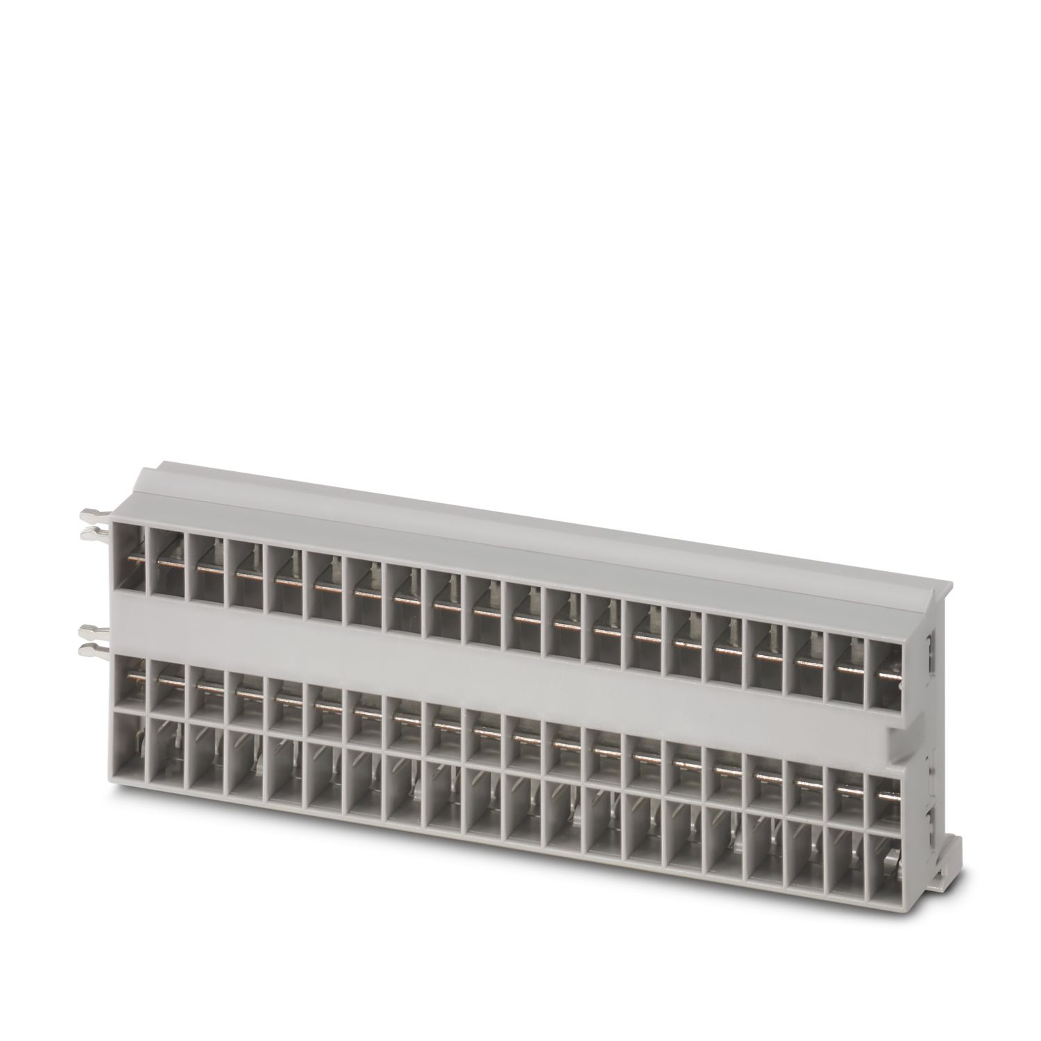
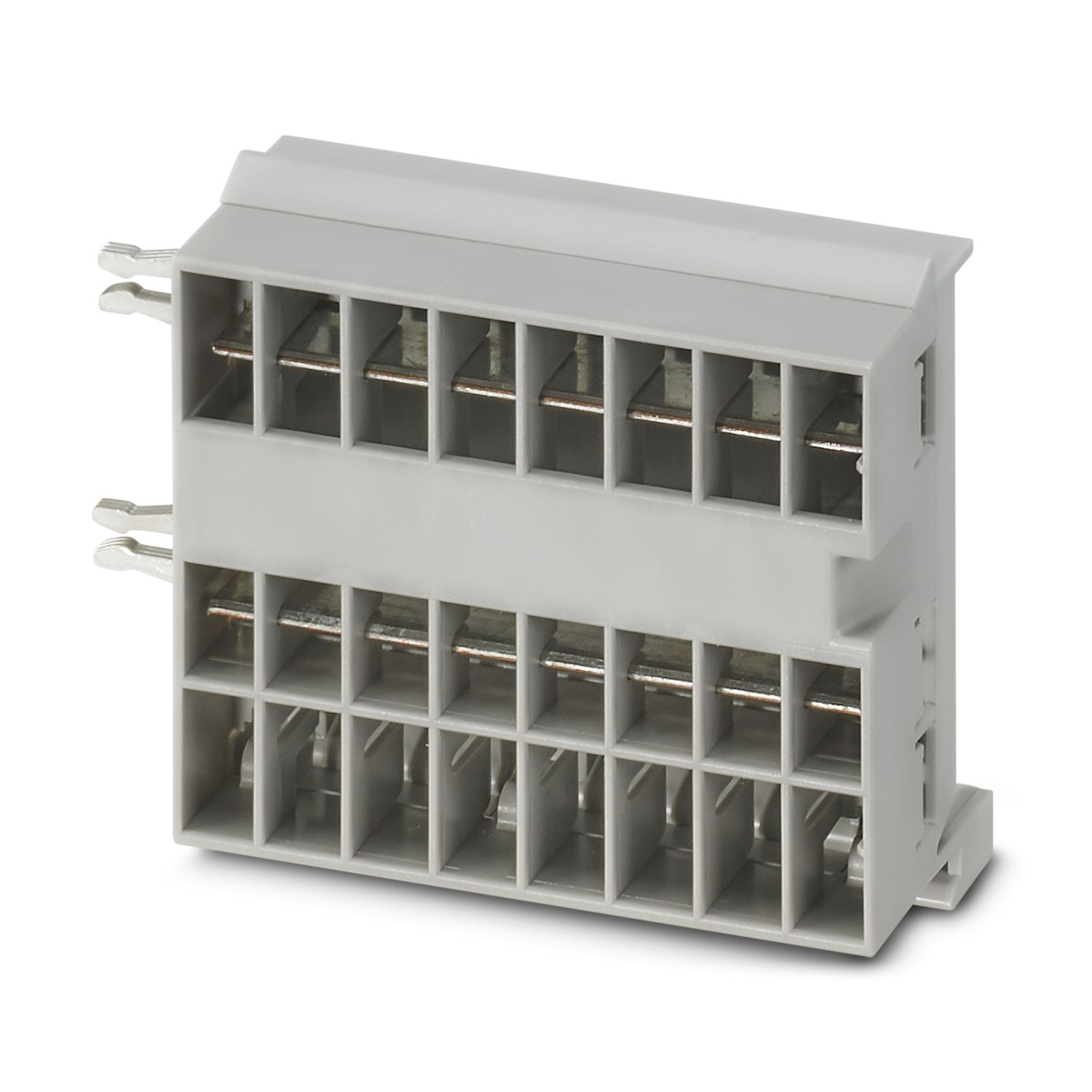
Potential distributor with Push-in connections for directly connecting the 0 V return conductor in the CAPAROC system. For DIN rail installation via the CAPAROC current rails.
This product needs further products for operation.
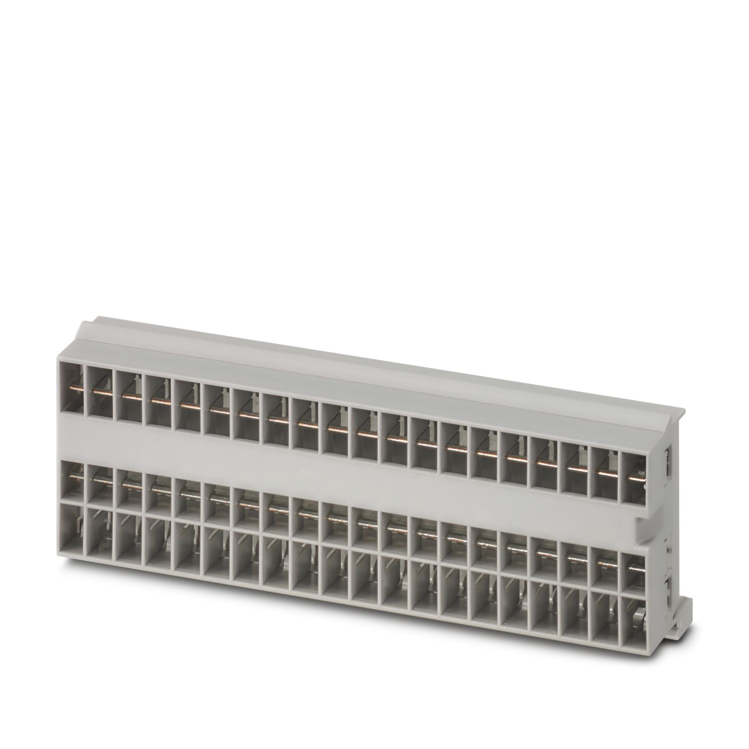
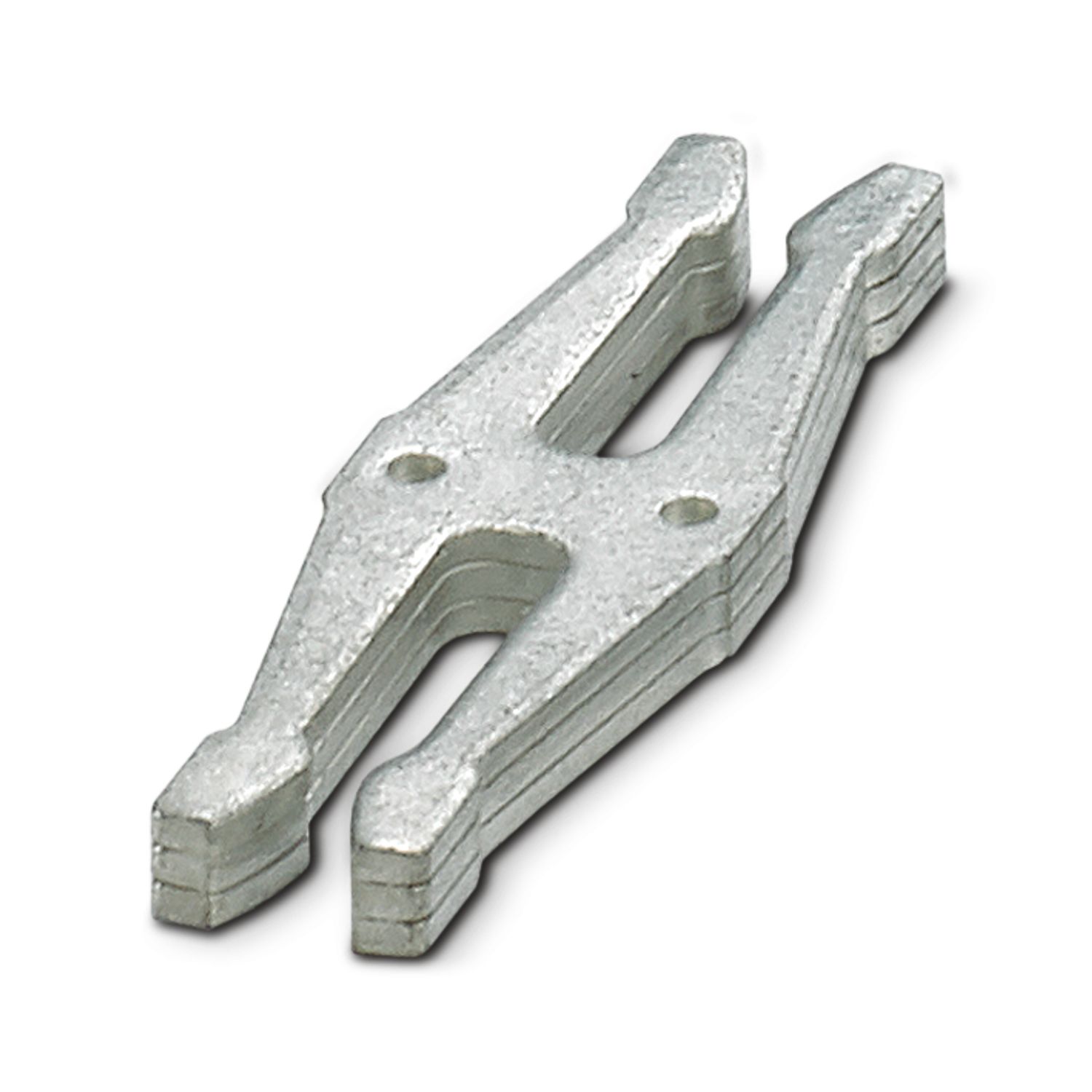
Mandatory accessories
Product details
| General | |
| Note | LABS release – in accordance with test specification VW PV 3.10.7:2005-0 |
| When connecting the conductor, make sure that the CAPAROC modules are not pulled apart due to tensile force. Gaps must not be created between the modules. | |
| Product type | Device circuit breakers |
| Product family | CAPAROC |
| Type | Plug-in module |
| Number of slots | 1 |
| Insulation characteristics | |
| Protection class | III |
| Pollution degree | 2 |
| General | |
| Operating voltage | 0 V DC ... 30 V DC |
| Rated voltage | 12 V DC |
| 24 V DC | |
| Rated current IN | 4x 10 A (per output) |
| 2x 20 A (per output) | |
| 40 A (Total) | |
| Rated surge voltage | 0.5 kV |
| Efficiency | > 99 % |
| Power dissipation | < 0.4 W (in nominal operation at 24 V and 4 x 10 A) |
| MTBF (IEC 61709, SN 29500) | 269532625 h (at 25 °C with 21 % load) |
| 269532334.5 h (at 40°C with 34.25% load) | |
| 269530881.5 h (at 60°C with 100% load) | |
| Voltage drop | 9.7 mV (at 10 A) |
| Load circuit | |
| Connection method | Push-in connection |
| Stripping length | 10 mm |
| Conductor cross-section flexible | 0.2 mm² ... 4 mm² |
| Conductor cross-section rigid | 0.2 mm² ... 4 mm² |
| Conductor cross-section AWG | 24 ... 12 |
| Conductor cross-section, flexible, with ferrule, with plastic sleeve | 0.25 mm² ... 4 mm² |
| Conductor cross-section, flexible, with ferrule, without plastic sleeve | 0.25 mm² ... 4 mm² |
| Dimensional drawing |
|
| Width | 6.2 mm |
| Height | 132.4 mm |
| Depth | 109.9 mm (incl. DIN rail 7.5 mm) |
| Color | light gray (RAL 7035) |
| Material | PA 6 |
| PA 6 | |
| PA 6 | |
| Flammability rating according to UL 94 | V-0 |
| Ambient conditions | |
| Degree of protection | IP20 |
| Ambient temperature (operation) | -30 °C ... 65 °C (The temperature range of the power module must be taken into consideration) |
| Ambient temperature (storage/transport) | -40 °C ... 70 °C |
| Altitude | ≤ 4000 m (amsl) |
| Humidity test | 96 h, 95 % RH, 40 °C |
| Shock (operation) | 30g (11 ms period, half-sine shock pulse, according to IEC 60068-2-27) |
| 25g (6 ms duration, half-sine shock pulse in accordance with IEC 60068-2-27, continuous shock) | |
| Vibration (operation) | 5g (10 Hz ... 150 Hz / 10 cycles / axis / X, Y, Z) |
| UL approval | |
| Identification | UL/C-UL Listed UL 508 |
| UL 121201 Class I, Division 2, Groups A, B, C, D, T4A | |
| Corrosive gas test | |
| Identification | ISA S71.04.2013 G3 Harsh Group A |
| Standards/specifications | EN 61000-6-2 |
| Note | EMC – Immunity for industrial areas |
| Standards/specifications | EN 61000-6-3 |
| Note | EMC – Emission for residential, business and commercial properties and small operations |
| Standards/specifications | EN 60068-2-78 |
| Note | Environmental influences – Moisture and heat, constant |
| Standards/specifications | EN 50178 |
| Note | Equipping power installations with electronic equipment |
| Standards/specifications | EN 60068-2-6 |
| Note | Environmental influences – Vibrations (sinusoidal) |
| Standards/specifications | EN 60068-2-27 |
| Note | Environmental influences – Shocks |
| Mounting type | pluggable onto CAPAROC CR… current rail |


Your advantages
The benchmark that you can tailor with direct pairwise integration into the system alongside the circuit breaker module
Particularly easy operation for everyone with tool-free insertion without additional wiring effort
Exceptionally easy design-in with color-coded pushers for clear identification of the potentials
Frequently asked questions
What functions does the negative distributor perform?
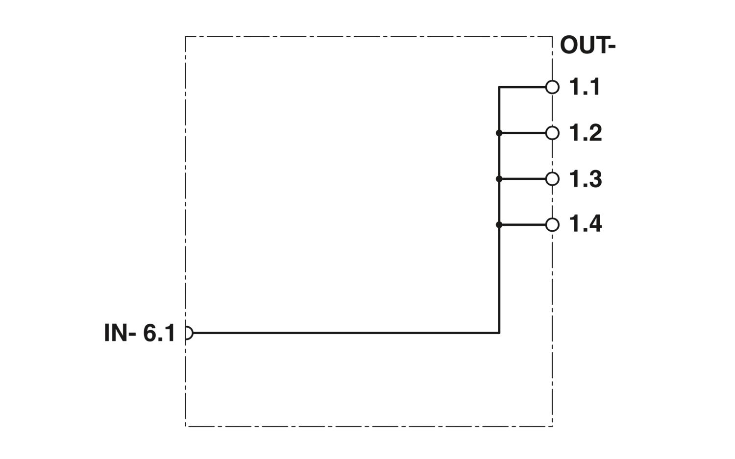
The 0 V potential distributor can be used to connect the return conductors of the load directly in the CAPAROC system. It offers four connection points to connect up to four loads directly.
Is there a hardware tutorial in which the CAPAROC functions are explained?
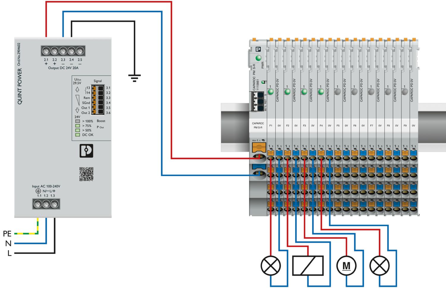
How many circuit breaker modules can I connect downstream of an infeed module?
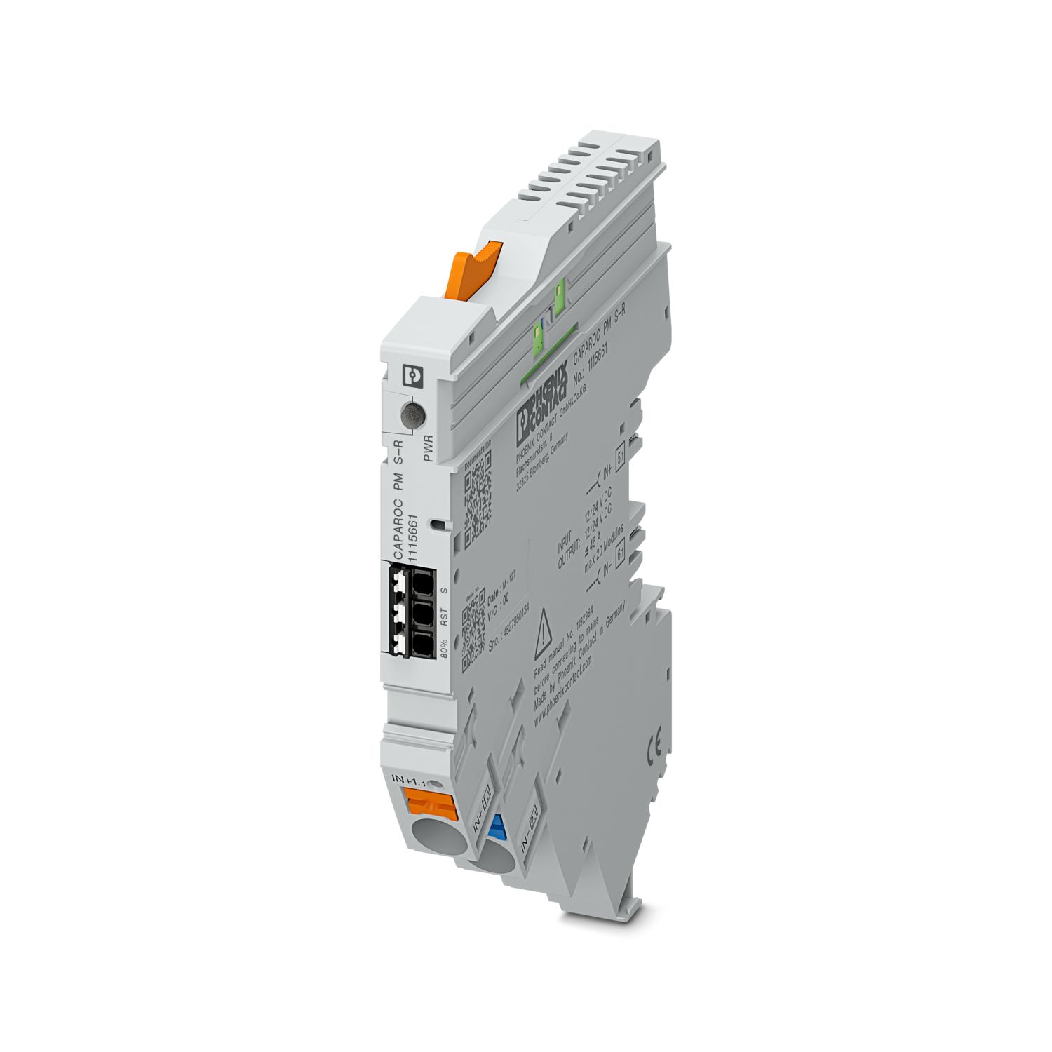
CAPAROC PM S-R: 20 circuit breaker modules
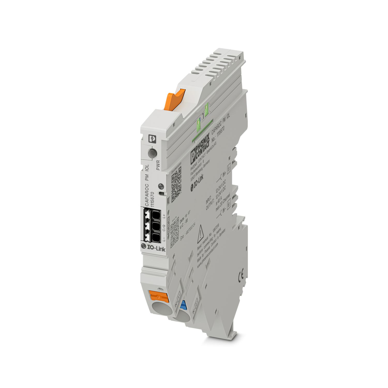
CAPAROC PM IOL: 20 channels
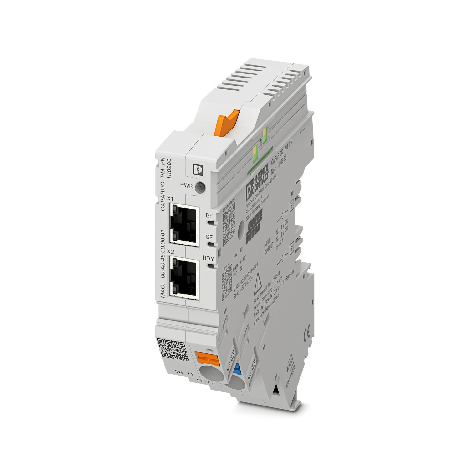
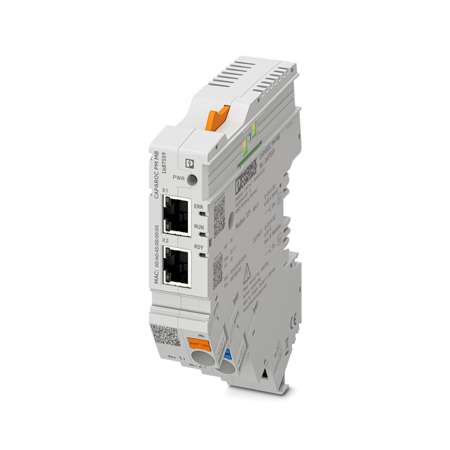
CAPAROC PM PN: 16 circuit breaker modules
CAPAROC PM EIP: 16 circuit breaker modules
CAPAROC PM MB: 16 circuit breaker modules
CAPAROC PM EC: 16 circuit breaker modules
The channel LED flashes yellow twice every 4 seconds. What does this mean?
This means that the internal communication to the power module is interrupted or faulty.
Check that the modules are mounted correctly and that there is no gap between the modules. If communication is still disrupted, check the side contacts of the...
View more
This means that the internal communication to the power module is interrupted or faulty.
Check that the modules are mounted correctly and that there is no gap between the modules. If communication is still disrupted, check the side contacts of the first module (left) that is flashing, if they are bent, either too far into the module, not centered in the housing opening or otherwise damaged, replace the module.
Can I block the setting of the set currents?
The currents can be locked in different ways:
1. Programming lock: press the PWR button on the power module for > 3 seconds, the PWR LED flashes yellow 3 x, the settings are now locked. Pressing it again for > 3 seconds causes the LED to fla...
View more
The currents can be locked in different ways:
1. Programming lock: press the PWR button on the power module for > 3 seconds, the PWR LED flashes yellow 3 x, the settings are now locked. Pressing it again for > 3 seconds causes the LED to flash green 3 times and unlocks it again.
2. The lock can also be set and released via the communication interface; the operating lock can also be set here, which prevents operation and settings on the device. The lock can then only be released via the interface.