
The terminal is designed for use within an Inline station. It is used to acquire analog voltage and current signals.
IB IL AI 2/SF-ME
-
Analog module
2863944
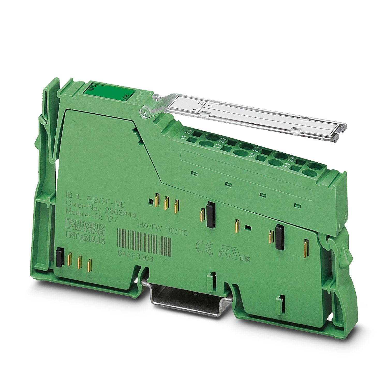


Inline, Analog input terminal, Analog inputs: 2, 0 V ... 10 V, -10 V ... 10 V, 0 mA ... 20 mA, 4 mA ... 20 mA, -20 mA ... 20 mA, connection technology: 2-conductor, transmission speed in the local bus: 500 kbps, degree of protection: IP20, including Inline connector and labeling field
Free download available.
Downloads
Product details
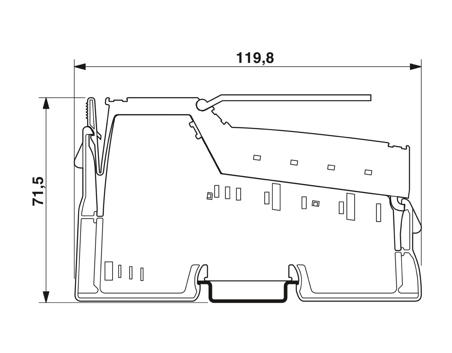
| Dimensional drawing |
|
| Width | 12.2 mm |
| Height | 119.8 mm |
| Depth | 71.5 mm |
| Note on dimensions | Housing dimensions |
| Note on application | |
| Note on application | Only for industrial use |
| Utilization restriction | |
| CCCex note | Use in potentially explosive areas is not permitted in China. |
| Color (Housing) | green (RAL 6021) |
| Inline local bus | |
| Number of interfaces | 2 |
| Connection method | Inline data jumper |
| Transmission speed | 500 kbps |
| Programming data (LocalbusSlave) | |
| Length code (hex) | 02 |
| ID code (dec.) | 127 |
| Length code (dec) | 02 |
| Process data channel | 32 bit |
| Input address area | 4 Byte |
| Output address area | 4 Byte |
| Parameter channel (PCP) | 0 Byte |
| Register length (bus) | 32 bit |
| Fieldbus data telegram (PROFIBUS) | |
| Required parameter data | 6 Byte |
| Required configuration data | 4 Byte |
| Analog: | |
| Input name | Analog inputs |
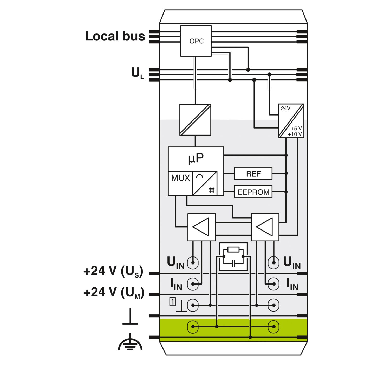
| Description of the input | Single-ended inputs, voltage or current |
| Number of inputs | 2 |
| A/D conversion time | typ. 120 µs (per channel) |
| Connection method | Inline connector |
| Connection technology | 2-conductor |
| Current input signal | 0 mA ... 20 mA |
| 4 mA ... 20 mA | |
| -20 mA ... 20 mA | |
| Input resistance current input | 50 Ω (Shunt) |
| Voltage input signal | 0 V ... 10 V |
| -10 V ... 10 V | |
| Input resistance of voltage input | > 220 kΩ |
| Data formats | IB IL, IB ST, IB RT, standardized representation |
| Limit frequency (3 dB) | 40 Hz |
| Common mode voltage range signal - ground | 40 V (Between current input and functional ground) |
| 40 V (between voltage input and functional ground) | |
| Measuring principle | Successive approximation |
| Measured value resolution | 13 bits (12 bits + sign bit) |
| Measured value representation | 13 bits (12 bits + sign bit) |
| Protective circuit | Surge protection; Suppressor diodes in the analog inputs |
| Product type | I/O component |
| Product family | Inline |
| Type | modular |
| Installation location | Control cabinet |
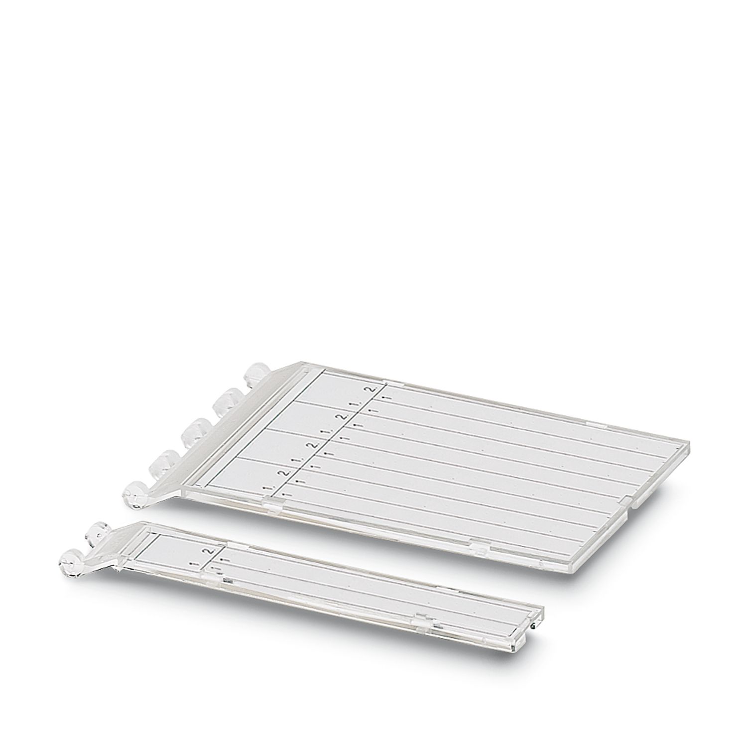
| Scope of supply | including Inline connector and labeling field |
| Operating mode | Process data operation with 2 words |
| Diagnostics messages | Failure of the internal I/O supply yes |
| I/O error Error message in the process data | |
| User error Error message in the process data | |
| Insulation characteristics | |
| Overvoltage category | II (IEC 60664-1, EN 60664-1) |
| Pollution degree | 2 (IEC 60664-1, EN 60664-1) |
| Maximum power dissipation for nominal condition | 0.9 W |
| Potentials: Communications power (UL) | |
| Supply voltage | 7.5 V DC (via voltage jumper) |
| Current draw | max. 60 mA |
| typ. 45 mA | |
| Potentials: Supply of analog modules (UANA) | |
| Supply voltage | 24 V DC (via voltage jumper) |
| Supply voltage range | 19.2 V DC ... 30 V DC (including all tolerances, including ripple) |
| Current draw | max. 18 mA |
| typ. 13 mA | |
| Electrical isolation/isolation of the voltage ranges | |
| Test voltage: 7.5 V supply (bus logic), 24 V supply UANA / I/O | 500 V AC, 50 Hz, 1 min |
| Test voltage: 7.5 V supply (bus logic), 24 V supply UANA / functional ground | 500 V AC, 50 Hz, 1 min |
| Test voltage: I/O/functional ground | 500 V AC, 50 Hz, 1 min |
| Connection technology | |
| Connection name | Inline connector |
| Inline connector | |
| Connection method | Spring-cage connection |
| Conductor cross-section, rigid | 0.08 mm² ... 1.5 mm² |
| Conductor cross-section, flexible | 0.08 mm² ... 1.5 mm² |
| Conductor cross-section AWG | 28 ... 16 |
| Stripping length | 8 mm |
| Ambient conditions | |
| Ambient temperature (operation) | -25 °C ... 55 °C |
| Degree of protection | IP20 |
| Air pressure (operation) | 70 kPa ... 106 kPa (up to 3000 m above sea level) |
| Air pressure (storage/transport) | 70 kPa ... 106 kPa (up to 3000 m above sea level) |
| Ambient temperature (storage/transport) | -25 °C ... 85 °C |
| Permissible humidity (operation) | 10 % ... 95 % (non-condensing) |
| Permissible humidity (storage/transport) | 10 % ... 95 % (non-condensing) |
| Mechanical test | |
| Vibration resistance in accordance with EN 60068-2-6/IEC 60068-2-6 | 5g |
| Shock in accordance with EN 60068-2-27/IEC 60068-2-27 | 25g |
| Protection class | III (IEC 61140, EN 61140, VDE 0140-1) |
| Mounting type | DIN rail mounting |
cULus Listed
Approval ID: E199827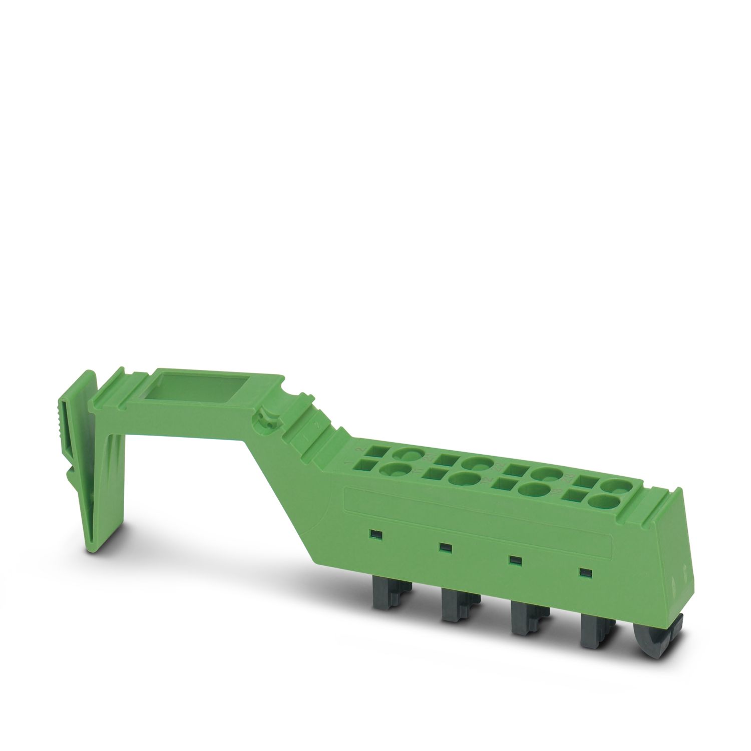

Your advantages
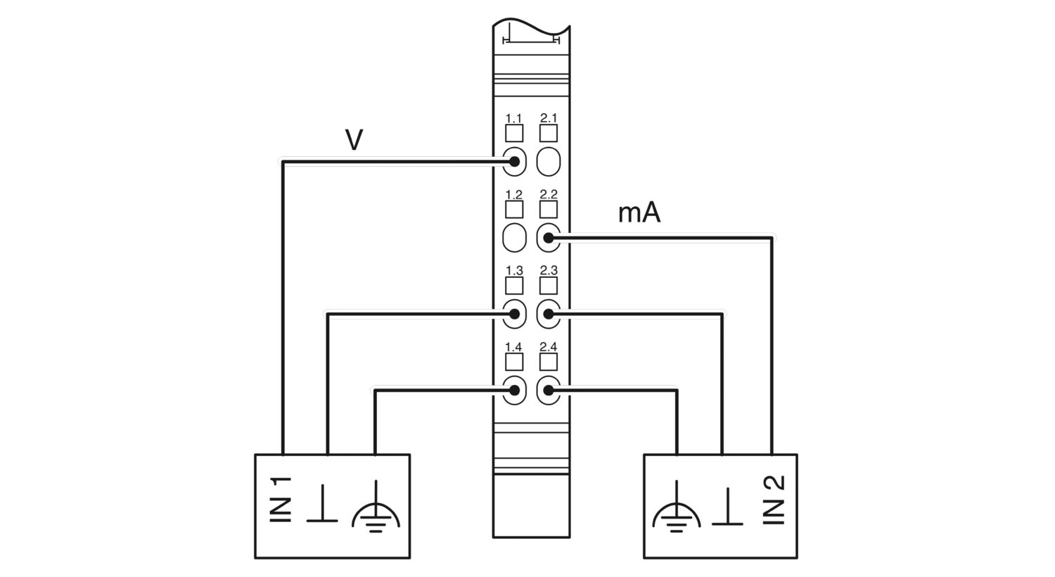
2 analog single-ended signal inputs for the connection of either voltage or current signals
Connection of sensors in 2-conductor technology
Current ranges: 0 mA ... 20 mA, 4 mA ... 20 mA, ±20 mA
Voltage ranges: 0 V ... 10 V, ±10 V
The channels are parameterized independently of one another via the bus system
Measured values can be represented in four different formats
Resolution: 12 bits + sign bit
Process data update of both channels within a max. of 1.5 ms