Starting up the charging controller
NOTE: Check for latest firmware prior to startup
Operate the charging controller with the latest firmware version. The latest firmware version is available for downloading at phoenixcontact.com/qr/1138965. Observe the change notes regarding the firmware version. Carry out a firmware update. For information on running firmware updates, refer to “System Control/Software” on page 134.
Notes on the configuration of the CHARX SEC-1000
You can configure the CHARX SEC-1000 charging controller in two different ways:
•Connect the charging controller to a CHARX SEC-1000. Perform the configuration via the web-based management. You can then disconnect the devices again and operate the CHARX SEC-1000 separately.
Note for configuration with CHARX SEC-3xxx:
Two Event Actions must be created. See “Charging Stations/Charge Point/Event Actions” on page 94.
Charging releases for stand-alone operation of a CHARX SEC-1000
The configured charging releases are processed via the application software on the CHARX SEC-3xxx. For stand-alone operation of a CHARX SEC-1000 charging controller, the charging release must be configured via Event Actions. An example of a corresponding event can be the connection of the vehicle to the charging station or an edge at one of the digital inputs.
•You can connect the charging controller to a PC via a USB CAN bus converter and an adapter cable. Configuration is performed via a software tool, which you can download in the download area for the charging controller at phoenixcontact.com/qr/1139034. Here, you will also find notes on operation of the software and on configuration of the adapter cable.
Access to CHARX SEC-3xxx charging controllers
You can access the CHARX SEC-3xxx charging controllers in two different ways. This access is required to make settings in the web-based management or to prepare the charging controller for use in the network.
1.Access via the USB-C interface and the USB slot on the computer
2.Access via an Ethernet network made up of the charging controller, router, and computer
3.Access via the Ethernet interface directly from the computer
No WBM or general Ethernet access via the ETH1 interface
The ETH1 interface is reserved for setting up client/server systems with additional CHARX SEC-3xxx charging controllers. The ETH1 interface is not available for access to the WBM or unrestricted operation in Ethernet networks.
Access via the USB-C interface
This is the preferred way, since it avoids restrictions in Ethernet networks.
•You must always download an RNDIS driver for your computer. You will find the driver at “catalog.update.microsoft.com”.
•Search for “USB\VID_0525&PID_A4A2” or “RNDIS Gadget”. Select a driver for your operating system, for example, the driver from Acer for “Win7/8.1/later”.
•Driver from Acer for “Win7/8.1/later”
•Download the driver. It is approximately 21 kB in size.
•Unpack the zip file to a directory, for example, c:\rndis-driver.
•Open the Device Manager on your computer by entering “Device Manager” in the search bar.
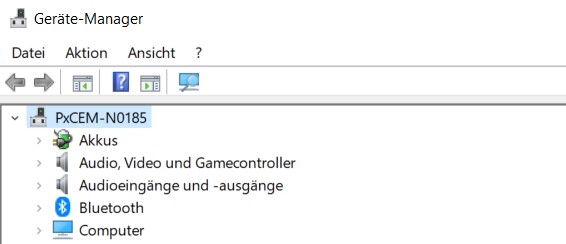
•Connect the CHARX SEC-3xxx to the computer.
•If the charging controller is already connected, you need to disconnect it briefly.
↪A device appears when a charging controller is connected and disappears again when it is disconnected. This is the interface for the charging controller. Depending on the operating system, its name is “USB Device” or similar.
•In the Device Manager for the newly found device, select the menu “Update Driver” and browse manually. Then select the target directory.
↪The driver is found in the target directory. The device is displayed under “Network, USB Ethernet/RNDIS Gadget”.
•Find the device with the installed driver at the IP address 192.168.5.1. Access the WBM by entering the address in the browser.
If access is not possible although the driver is installed, it may be for one of the following reasons:
–The computer is attempting to establish the connection via an Ethernet or WLAN interface. In this case, disable the interfaces for a brief period.
–The driver was not assigned to the correct interface. Check which interface appears or disappears by connecting and disconnecting the module.
Access via an Ethernet network with router
•Connect the charging controller to a router via the ETH0 interface.
•Connect your computer to the router as well.
↪The ETH0 interface is set at the factory to dynamic address assignment by a DHCP server. Once the address has been assigned by the router, the interface can be found in the network.
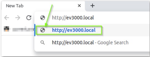
↪Depending on the system, the charging controller can be accessed at http://ev3000.local or http://ev3000.
If multiple charging controllers are integrated in a network via DHCP, successive consecutive numbers are attached to the subsequent charging controller names (ev3000-2, ev3000-3, etc.). The charging controllers can then be accessed accordingly via these names.
Procedure in case of limited access rights
If you are operating in a network with limited access rights, the address assignment is frequently blocked or your computer is not able to find the charging controller. In this case, you must search the network for the IP address or select a different access method.
Local search for the charging controller
Avoid using a search engine to search for the charging controller. Establish a direct connection.
If possible, use HTTPS to access the web-based management of the charging controller. To do so, enter https:// followed by the IP address in the address line of the browser (e.g., https://192.168.5.1).
Access via the Ethernet interface directly from the PC
The initial connection to the charging controller can also be established without a router. In this case, there is generally no DHCP server available to assign an IP address to the charging controller.
–To assign an IP address initially with your PC, you need a corresponding program. Phoenix Contact recommends “Rockwell BOOTP/DHCP Server 2.3”.
–The program detects BootP and DHCP requests and can manually assign an IP address to the charging controller based on the requests.
WBM – Dashboard and Login
You can use the web-based management (WBM) to read static and dynamic frame data and to make configuration settings.
Standby time until the WBM is started
To ensure rapid availability in operational mode after restarting the charging controller, one of the last processes to be started is the WBM. This can result in a delay until the full scope of functions of the WBM is available.
Press F5 to refresh the web page in the browser and update the status of the WBM.
Following successful login, you can access further areas of the WBM.
Login
–Language selection
–Login
–User roles
–Change password
–Dashboard
–Summary of the connected charging controllers
Charging Park
–Status indicators and configuration of the individual charging controllers
–Status indicators and configuration for operation on an OCPP backend
–Status indicators and displays for load management
–Display and management of the local whitelist
System Control
–General system status and version information
–Display and setting of the time
–Network configuration and connection status
–Modem settings and connection status
–Download of log files for diagnostic purposes
–Module switch-over to client/server mode
–Software update
Dashboard
When you access the WBM via the browser, the dashboard provides you with an overview of all charging points that are connected and set up via this charging controller. This includes additional extension modules on the backplane bus. If the charging controllers are operating in a client/server group, further clients together with their respective extension modules will be shown.
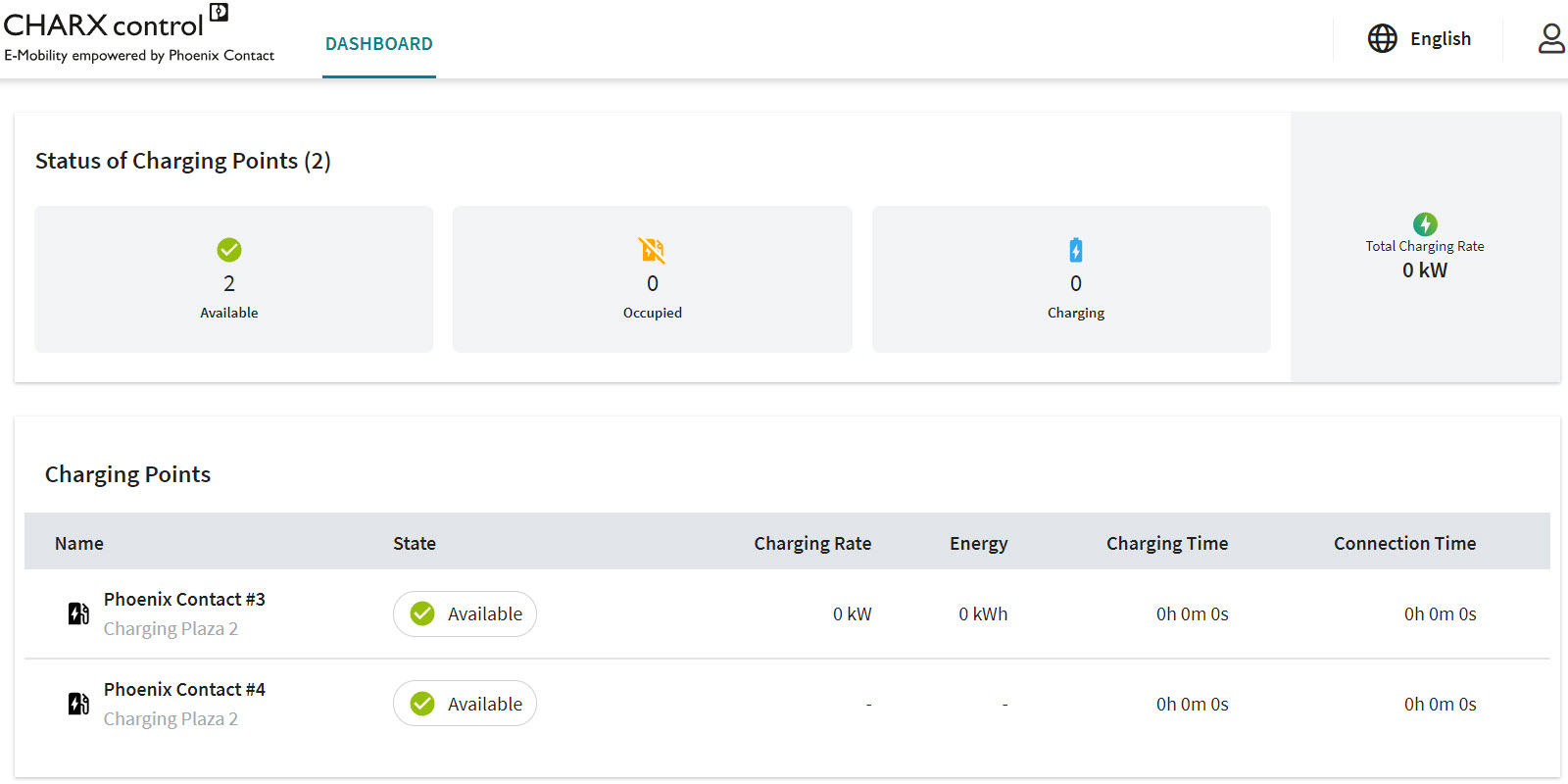
The overview provides a summary of the connected charging controllers:
–Number of charging points available for new charging processes
–Number of occupied charging controllers without an active charging process
–Number of charging controllers currently engaged in a charging process
–Total power currently being charged at all connected charging controllers
The following information is displayed for the individual charging controllers:
–Name and location of the charging controller (specified in the configuration)
–Current status
–Current power (for active charging processes)
–Amount of energy currently being charged
–Charging time
–Plug-in duration
Only configured charging points are visible in the dashboard
Only charging points that are configured are shown in the dashboard view.
Language selection
You can switch between the following languages via the language selection option:
–German
–English
Login
When you access the WBM, you are logged in to the charging controller in the “Guest” user role and will not have any other rights. For other activities, you must log in with the appropriate user role. To do this, click the figure icon in the upper right-hand area of the screen.
Figure 5-5Login to the WBM![]()
User roles
The WBM provides various user roles with corresponding login and different rights.
|
Rights |
|||
|---|---|---|---|
|
Guest |
“---” |
“---” |
Read-only access only to the dashboard |
|
User |
“user” |
“user” |
All read-only access rights, charging releases, editing of whitelists, download of log files |
|
Operator |
“operator” |
“operator” |
User rights, plus settings required for operation and local startup (network, backend, load management), software updates |
|
Manufacturers |
“manufacturer” |
“manufacturer” |
No restrictions |
Change Password
NOTE: Change your password regularly
To prevent misuse and invalid device settings, change your passwords during startup at the installation location, at the very latest. Assign a new password for your user role by clicking the “Profile” button.
NOTE: Log out when not using the WBM
To prevent misuse and invalid device settings under your user profile, log out by clicking the “Logout” button if temporarily not using the WBM.
WBM – Charging Stations
Configuration of the charging stations
Clicking “Charging Stations/Overview” opens an overview of all charging stations and charging points. A displayed charging station can have up to twelve charging points.
Figure 5-7Charging Stations/Overview
Figure 5-8Charging station and charging point
Charging park (A)
A charging park consists of all the charging controllers combined in a network. A charging park has a server, clients connected via Ethernet, and extension modules attached to the clients or the server.
For example: A Variable „Product Area 1“ ist nicht definiert module as the server, with attached Variable „Product Area 5“ ist nicht definiert extension modules, which are connected to additional Variable „Product Area 3“ ist nicht definiert modules and attached extension modules.
Charging station (B)
A charging station is a grouping of precisely one server or client module. Additional extension modules can be attached to the server or client module.
For example: A Variable „Product Area 1“ ist nicht definiert module with additional attached Variable „Product Area 5“ ist nicht definiert modules.
Charging point (C)
A charging point is precisely one charging interface with the associated I/O device.
For example: The charging interface of the Variable „Product Area 1“ ist nicht definiert module or a Variable „Product Area 5“ ist nicht definiert module.
Charging stations
Figure 5-9 shows a charging park view together with the respective status of the charging stations and charging points. The charging park consists of a charging station with two charging points. The charging points are a Variable „Product Area 2“ ist nicht definiert and Variable „Product Area 5“ ist nicht definiert.
Figure 5-9Importing a configuration
In the charging park view, you can import configurations to the charging points (1) or access the charging point details (2).
You can run the individual charging points with different configurations. You can export the configurations beforehand from a configured charging point. Exporting makes it easier to reproduce charging point configurations.
•Click the “IMPORT CONFIGURATION” button.
•Importing charging point configurations
Proceed in accordance with • to import configurations:
•Select the saved configuration file (A)
•Select the charging point to which you want to transfer the configuration (B)
If you configure multiple charging points in a charging park with the same file, then you can automatically add an incrementing extension “-1”, “-2”, etc. to the charging point names stored in the configuration file (C).
If an existing configuration is not available, you can view the charging points on an individual basis and edit them step by step. To do this, select the respective charging point (see “Charging Stations/Charge Point/Configuration” on page 88).
Charging Stations / CHARX RFID/NFC Board
In the “Charging Stations | CHARX RFID/NFC Board” menu item, the “CHARX RFID/NFC PCB” is configured. Various events and actions of the LED profiles are configured here. In addition, the volume of the audible signal device (buzzer) can be set.
To enable the configuration of the CHARX RFID/NFC board, the RFID reader type must be set to “CHARX RFID/NFC” on at least one charging point (see “Configuration of the charging stations” on page 78).
Figure 5-10CHARX RFID/NFC Board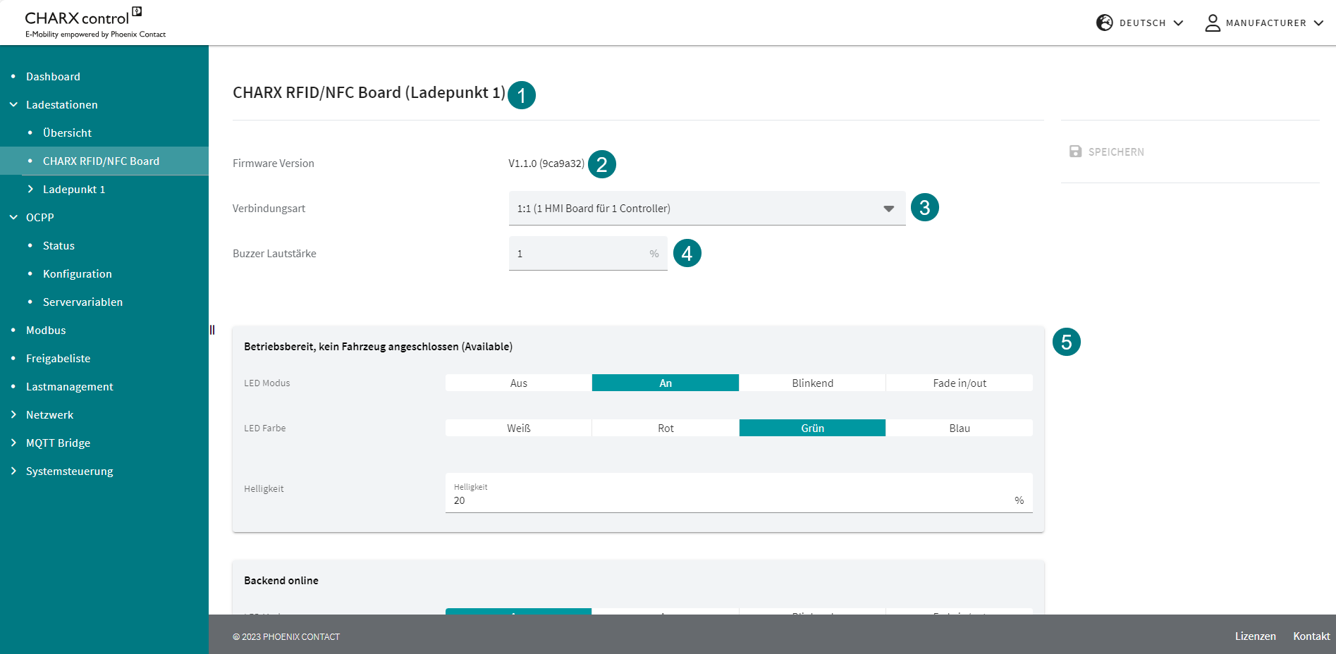
If several CHARX RFID/NFC boards are installed in the charging park, individual configuration of the individual devices is possible. The charging point name describes the charging point to which the CHARX RFID/NFC board is connected. Several connected CHARX RFID/NFC boards are displayed one below the other.
If new firmware is available for the CHARX RFID/NFC board, this is automatically installed. The firmware is part of the RAUC bundle for the CHARX charging controllers. The firmware version of the CHARX RFID/NFC board is displayed in the WBM. The “Connection Type” field configures the LED profiles that can be used. Here, the CHARX RFID/NFC board differentiates between the different operating modes:
CHARX SEC-1000 (stand-alone)
–CHARX SEC-3xx0 (1:1)
–Group of several CHARX SEC-3xx0 modules (1:n).
The following table provides an overview of the profiles used for the individual operating modes:
|
Profile |
Connection type |
Note |
||
|
Stand-alone |
1:1 |
1:n |
||
|
Controller booting |
Is not currently used |
|||
|
Ready for operation, no vehicle connected |
x |
x |
- |
|
|
Backend online |
- |
- |
x |
Only in conjunction with OCPP |
|
Backend online and charging point available |
- |
x |
- |
Only in conjunction with OCPP |
|
Backend offline, but charging point available |
- |
x |
- |
Only in conjunction with OCPP |
|
Vehicle connected, charging process active |
x |
x |
- |
- |
|
Vehicle connected, waiting for authorization |
x |
x |
x |
- |
|
Authorization request ongoing |
- |
x |
- |
- |
|
Vehicle connected, charging process completed |
- |
x |
- |
- |
|
Charging point locked, reserved |
x |
x |
- |
- |
|
SuspendedEV |
x |
x |
- |
- |
|
SuspendedEVSE |
x |
x |
- |
- |
|
Charging point offline |
x |
Only in conjunction with OCPP |
||
|
Not ready for operation |
x |
x |
x |
- |
|
Waiting for RFID card to add/delete |
x |
x |
x |
- |
|
RFID accepted |
x |
x |
x |
- |
|
RFID not accepted |
x |
x |
x |
- |
The volume of the audible signal device (buzzer) can be adjusted between 0% and 100%. The perceived volume is not necessarily correlated with the set volume and depends on the frequency.
The LED mode can be set individually for each profile:
LED mode: Off, On, Flashing, Fade In/Out
–LED color: White, red, green, blue
–Brightness: 0% to 100%
The period time is specified in milliseconds for the “Flashing” and “Fade In/Out” LED modes. In “Fade In/Out” mode, the minimum and maximum brightness can also be set (pulsating LED brightness).
The “RFID accepted” and “RFID not accepted” profiles are events and are displayed for one second. Reading of an RFID card is confirmed with a signal tone. In addition, an audible signal indicates whether the card has been accepted or not.
CAUTION: Optical radiation
The LED of the product emits dangerous optical radiation. This is potentially harmful to the eyes and can cause impaired vision.
–Do not stare at the light source.
Charging Stations/Charge Point/Status
You access the “Charge Point Status” view by clicking the “Status” button under the selected charging point (see Figure 5-9).
The “Charge Point Status” view contains the “Status” page, which displays information (1) and operating options (2) for the charging point.
The only user with full operational authorization for charging points is the “Manufacturer”.
Figure 5-11Charge Point Status
The information is divided into the following groups:
–Current charging status
–Device information
–Base module
–Bus communication
–Energy measuring device
–Charging point details
–ISO 15118-specific status data
The information (1) is shown in Table 5-3.
Operation (2) is described in Table 5-4.
|
Charging Stations | Charge Point | Status |
||
|---|---|---|
|
CHARX Charge Point X |
||
|
Status |
The same display as on the dashboard. The current status of the charging point is shown here. –Available –Occupied –Charging –Reserved –Error (see “Error codes” on page 149) |
|
|
Local Bus State |
The status of the bus communication connection. |
|
|
Charging Duration |
The total duration that the connected vehicle was in “Charging” status or status “C”. This time is normally shorter than the plug-in duration. |
|
|
Plug-in Duration |
The plug-in duration indicates the total time the charging point has been in the “Occupied”, “Charging”, or “Error” state, and resets to “0” when the vehicle is disconnected. |
|
|
Charging Current Limit (PWM) |
The charging current setting that the charging controller is currently communicating to the connected vehicle. The setting is always 0 A when a vehicle is not connected. |
|
|
Measured Current L1 | L2 | L3 |
The currents currently measured at the charging point are displayed. If no measuring device is connected, the currents are displayed as not available. |
|
|
Charged Energy |
The charged energy during the current charging process is displayed. If no measuring device is connected, “Not Available” is displayed here. If no measuring device is configured, this data is not visible. |
|
|
Charging Power |
The current charging power is displayed. If no measuring device is connected, then it is shown as not available. If no measuring device is configured, this data is not visible. |
|
|
Device Info |
||
|
Device Name |
Factory designation of the charging controller |
|
|
Device UID |
The Device UID is unique throughout the charging park. It can be used to clearly identify a charging controller. The UID that can be read here can also be used for communication from a higher-level system (e.g., MQTT). |
|
|
Base Module |
||
|
Hardware version |
Hardware version of the charging station |
|
|
Firmware version |
Firmware version of the charging station. This can be updated via the “System Control/Software” menu (“System Control/Software” on page 134). |
|
|
Bus Communication |
||
|
Backplane Bus Position |
The position in the backplane bus helps identify the current charging controller in question. “1” is the server or client module, “2” to “12” are extension modules. |
|
|
Head Module IP Address |
The IP address via which the server or client module of the charging point can be accessed. |
|
|
Head Module MAC Address |
MAC address of the server or client module |
|
|
Energy Measuring Device The information on the energy measuring device is only displayed if an energy measuring device is connected. Otherwise, “Not Available” is displayed in the relevant fields. |
||
|
Current L1 |
Momentary current on phase L1 of the energy measuring device |
|
|
Current L2 |
Momentary current on phase L2 of the energy measuring device |
|
|
Current L3 |
Momentary current on phase L3 of the energy measuring device |
|
|
Voltage U1 |
Current voltage U1 of the energy measuring device |
|
|
Voltage U2 |
Current voltage U2 of the energy measuring device |
|
|
Voltage U3 |
Current voltage U3 of the energy measuring device |
|
|
Total Energy |
Total counter value of the energy measuring device |
|
|
Power Factor |
Power factor of the energy measuring device |
|
|
Frequency |
Mains frequency applied at the energy measuring device |
|
|
Charge Point Details |
||
|
Status |
Status of the charging point in accordance with IEC 61851-1 |
|
|
Current RFID |
If an RFID card has been read by the RFID reader configured in the charging point, the RFID tag is displayed here. |
|
|
External Temperature |
If a temperature evaluation is configured, then the read temperature is displayed here. |
|
|
ISO 15118 If communication via ISO 15118 is configured in the charging point configuration, the ISO 15118 section is displayed below the charging point details. If ISO 15118 is not configured, then no further information is displayed here. |
||
|
Start Charging Time (UTC) |
The time that the vehicle gives as the desired time to start charging. This is the time at which the charging process starts. |
|
|
Scheduled Departure Time (UTC) |
The time that the vehicle gives as the scheduled departure time. |
|
|
Charging Progress (15118) |
The current charging progress is displayed. –Start: The process is running. –Stop: Charging is stopped. –Renegotiate: The vehicle renegotiates with the charging point. |
|
|
Session ID |
The session ID describes the process with a unique number. |
|
|
EVCC ID |
The EVCC ID given by the vehicle. |
|
|
Energy Transfer Mode |
The energy transfer mode requested by the vehicle can either be “AC_single_phase_core” or “AC_three_phase_core” and determines how many phases are used to charge the vehicle. |
|
|
TCP Connection Status |
Status of the TCP connection: UNKNOWN, DISCONNECTED, CONNECTED |
|
|
QCA Link Status |
Status of the QCA link: UNKNOWN, NOT_AVAILABLE, DOWN, UP |
|
|
Charging Stations | Charge Point | Status (Operation) |
|
|---|---|
|
Disable or Enable Charge Point |
If the charging point is active, it can be disabled using this button. The charging point is set to status F (in accordance with IEC 61851-1) and shown as being in “Error” state. An active charging process is aborted. The same button is used for activation. |
|
Allow or Prohibit Charging |
When a vehicle is connected to the charging point, charging can be enabled by the operator of the web page. Charging can be prohibited using the same button. |
|
Enforce or Revert Unlocking |
If unlocking cannot be performed on the vehicle side, it can also be performed via the web page. An active charging process is aborted. The “Enforce Unlocking” state must be maintained until the connector has been removed from the charging socket. The enforced unlocking can then be reverted. |
|
Only available for the user “Manufacturer” |
|
|
Import Configuration |
A previously saved configuration can be loaded onto the charging controller via the “IMPORT CONFIGURATION” button. The current configuration on the selected charging point will be overwritten and cannot be restored. The available charging controllers are displayed in order of their backplane bus position. |
|
Export Configuration |
The configuration is exported as a JSON file and is normally saved in the “Downloads” folder. |
|
Delete Configuration |
A configuration can only be deleted if the charging point is configured. Pressing the button restores the charging point to its factory default configuration. The deletion of the configuration cannot be undone. A configuration can be exported beforehand as a backup. |
Charging Stations/Charge Point/Configuration
When a charging controller is in the factory default configuration, the charging point is not configured. The charging controller is configured for the first time under “Create configuration”. The name of the menu changes to “Configuration” later in the process. You can copy the configuration of a different charging point at the top of the page. This makes it easier to create identical or almost identical charging points. Figure 5-12 shows the configuration page view.
Figure 5-12Configuration page for an unconfigured charging point
Settings for the charging point name and location are required. The name serves to uniquely identify the charging point and configuration. The charging controller you assign to the charging point is identified by a UID. If you change the settings, click the “Save” button to save your changes.
The remaining structure of the configuration is divided into different areas. The available areas are: Charging Connection, Energy, Monitoring, Release Charging, and ISO 15118.
|
The settings for “Charging Connection” cover the area between the charging controller and the vehicle. |
|
|
Type of connection from the charging point. –Socket Outlet: A charging socket is mounted at the charging point. The connection is established by a mobile charging cable. –Connector: A permanently connected charging cable with charging connector is attached to the charging point. |
|
|
Standard |
Standard of the charging socket to be connected. –IEC 62196 This setting is only available in conjunction with the “Socket Outlet” connection type. |
|
Socket Outlet Type |
In this field, you select the charging socket type. This is abbreviated in accordance with the actuator selection in the item designation. –4-pos. charging socket, Marquardt type actuator –4-pos. charging socket, Küster type actuator –3-pos. charging socket, Hella type actuator This setting is only available in conjunction with the “Socket Outlet” connection type. |
|
You select the moment when the actuator should lock the charging socket. –On EV connected – disconnected: As soon as a vehicle is connected to the charging socket, it is locked. Disconnection on the vehicle side is required first to unlock the charging socket. –Remote control: Locking is not controlled automatically, instead it must be controlled externally. This can be done via OCPP (corresponding configuration required), Modbus, or the REST API, for example. This setting is only available in conjunction with the “Socket Outlet” connection type. |
|
|
Plug Rejection |
Charging connectors with cables with low current carrying capacity will be rejected by the charging controller. In this case, charging does not take place and the charging point switches to the error state. –Reject 13 A –Reject 20 A & 13 A This setting is only available in conjunction with the “Socket Outlet” connection type. |
|
Status D Vehicle Rejection |
The charging controller rejects or accepts vehicles that require additional ventilation. –Reject –Accept |
|
Charging current settings and settings for the energy measuring device are made in the “Energy” area. The settings are not linked; charging current settings are also valid without an energy measuring device. |
|
|
Energy | Charge Currents |
|
|
Charge Current Minimum |
The configured minimum set current of the charging point in amps. |
|
Charge Current Maximum |
The configured maximum set current of the charging point in amps. The set current is always within the limits of the minimum and maximum charging current. |
|
Fallback charging current, in amps. This charging current setting is automatically set when the fallback time has elapsed. |
|
|
Fallback time in seconds. In the event that the connection to the relevant front module is lost, the charging controller waits a certain amount of time before switching to the fallback charging current. During an active connection, the elapsing timer is repeatedly increased to the fallback time and therefore the fallback charging current is not applied. |
|
|
Energy | Energy measuring device settings |
|
|
Energy Measuring Device Type |
You select the energy measuring device type here. –Phoenix Contact EEM-350 EEM-350-D-MCB, 2905849 –Phoenix Contact EEM-EM357/EEM-DM357 EEM-EM357, 2908588 EEM-DM357, 252817 EEM-DM357-70, 1219095 –Phoenix Contact EEM-EM357-EE EEM-EM357-EE, 1311985 –Phoenix Contact EEM-157-EE EEM-EM157-EE, 1311993 –Phoenix Contact EEM-AM157-70 EEM-AM157-EE, 1219090 –Carlo Gavazzi EM24 –Carlo Gavazzi EM340 –Carlo Gavazzi EM111 –Inepro Metering PRO380 –Iskra WM3M4(C) |
|
You define the phase rotation at the measuring device connection here. This configuration is not required, but does improve load management behavior and makes it possible to limit out-of-balance loads. This setting can only be set in conjunction with a configured energy measuring device type. |
|
|
Calibration Law |
|
|
Charge Point Abbreviation for Screen |
The specified abbreviation is shown on the display. |
|
Selection of the charging point: |
Selection of the charging point: Via RFID reader: –Via screen: –The settings are only relevant if the calibration function is used. |
|
Monitoring | Protection The safety equipment detects errors at the charging point and switches the charging point to the error state. Safety equipment is configured in the “Monitoring” settings. Connect the safety equipment in accordance with “Connecting and wiring the hardware” on page 51. |
|
|
Load contactor monitoring is used to detect a non-opening contactor. Specify one of the digital inputs for this. |
|
|
Select the type of the auxiliary contact for monitoring. N/C contact: When the contactor is stuck, the contact is open and no voltage is applied. N/O contact: When the contactor is stuck, the contact is closed and 12 V are applied. |
|
|
You can enable or disable DC residual current monitoring via a check box. The residual current sensor must be connected in accordance with “Operation without a DC residual current sensor – with a type B residual current device” on page 59. |
|
|
Monitoring | Charge Current Monitoring Charging current monitoring is only possible if a measuring device is configured. The charging current can then be checked for an impermissible overrange or out-of-balance load of the defined set current. |
|
|
Over Current Detection |
Select the type of overcurrent monitoring. –EV/ZE Ready: Derating is performed in defined stages as per the EV/ZE Ready standard. –Overcurrent shutdown: Shutdown in the event of an overcurrent in a time period of 100 s (>110% of the set current) or 10 s (>120% of the set current) If overcurrent monitoring has been triggered, charging is started again after one minute. If overcurrent occurs again, an error status is set for the charging point. |
|
Out-of-balance suppression to a maximum of 20 A can be enabled and disabled via the check box. Out-of-balance suppression is implemented for each charging point. |
|
|
Monitoring | Derating Derating is performed in the event that a measured temperature is exceeded. The derating function can be configured as linear derating or as activation. The connection and method of operation is illustrated in “Connecting temperature sensors” on page 69. |
|
|
Sensor Type |
Select the sensor type for temperature monitoring and derating here. –Pt 1000: A Pt 1000 sensor is connected to the charging controller. Then you can configure the start temperature, stop temperature, start current, and stop current. –PTC: A PTC chain is connected to the charging controller. Then you can configure a terminating resistor. |
|
Start Temperature (when Pt 1000 is selected) |
Temperature in °C at which derating begins. To ensure that derating is applied, the start temperature must be less than the end temperature. The start current must be greater than the end current. |
|
Stop Temperature (when Pt 1000 is selected) |
Temperature in °C at which derating stops the charging process. |
|
The charging release determines when a vehicle is authorized to charge. Without a charging release, the vehicle stays in status B. |
|
|
Via Dashboard: The release is only issued via the web page and must be issued manually. This is only possible on the dashboard and the status page of the charging controller. By Local Whitelist: The whitelist, which is checked when an RFID card or EVCC ID is presented, is stored locally on the charging controller. The RFID cards or EVCC IDs must be managed under “Whitelist”. Via Remote Control: The release is issued and withdrawn via an external system. For example, the release is issued via the REST API or Event Actions. Permanent Charging Release: The charging release is issued on a permanent basis and is not withdrawn. The charging release cannot be withdrawn via the web page. If the charging release is to be withdrawn, the charging point can be unlocked or locked. The release is issued and withdrawn via the connected OCPP backend. Additional release via the web page is not possible.
Via Modbus: The release is issued and withdrawn via the Modbus registers. Additional release via the web page is not possible. |
|
|
The RFID reader used at the charging point is specified via the RFID reader terminal point. All the charging points available in the network are therefore listed here. For example: “Chargepoint 2”. This means the RFID reader at “Chargepoint 2”. |
|
|
Type of RFID Reader |
You can select the type of the RFID reader. –ELATEC TWN4 –DUALI MDE 950-4 XCP –Netronix UW-XEU1 –CHARX RFID/NFC |
|
RFID Timeout |
Time after which a charging release via RFID is discarded if no vehicle is connected. The time is specified in seconds. |
|
OCPP ConnectorID |
The default value is “-1”. You must specify an ID here; this ID must be unique in the charging park. You must specify the ID starting from 1. The ID represents the ID in the OCPP backend.
|
|
ISO 15118 You must make special settings to activate ISO 15118 communication on the CHARX SEC-3050 and -3150 modules. |
|
|
ISO 15118 communication is activated via the High Level Communication (HLC) setting. –Required: Only vehicles with HLC can be charged at the charging point. –Optional: Vehicles with HLC as well as vehicles without HLC can be charged. –Disabled: There is no HLC, i.e., no communication in accordance with ISO 15118, at the charging point. |
|
|
EVSE ID |
The assigned EVSE ID for the charging point is entered here. The format is “CountryCode”+ “Operator ID” + “E”+ “ChargingStation ID”, e.g., DE123E4567 |
|
The vehicle can be informed via HLC that charging is free. This option is selected via the check box. |
|
|
Payment Options |
Payment can either be made by means of vehicle identification or conventional external payment. If certificates cannot be loaded via the web page, customers can only select the following option: Allow External Payment. |
|
TLS Policy |
Certificates cannot be loaded via the web page at present. The TLS policy is for display purposes only. |


Charging Stations/Charge Point/Event Actions
In the “Charging Stations | Charge Point | Event Actions” menu item, specific actions can be assigned to events that occur. The combination of an event and action is referred to as an Event Action. The current state of the inputs and outputs of the controller is shown in the top area of the web page in Figure 5-13.
Figure 5-13View of the Event Actions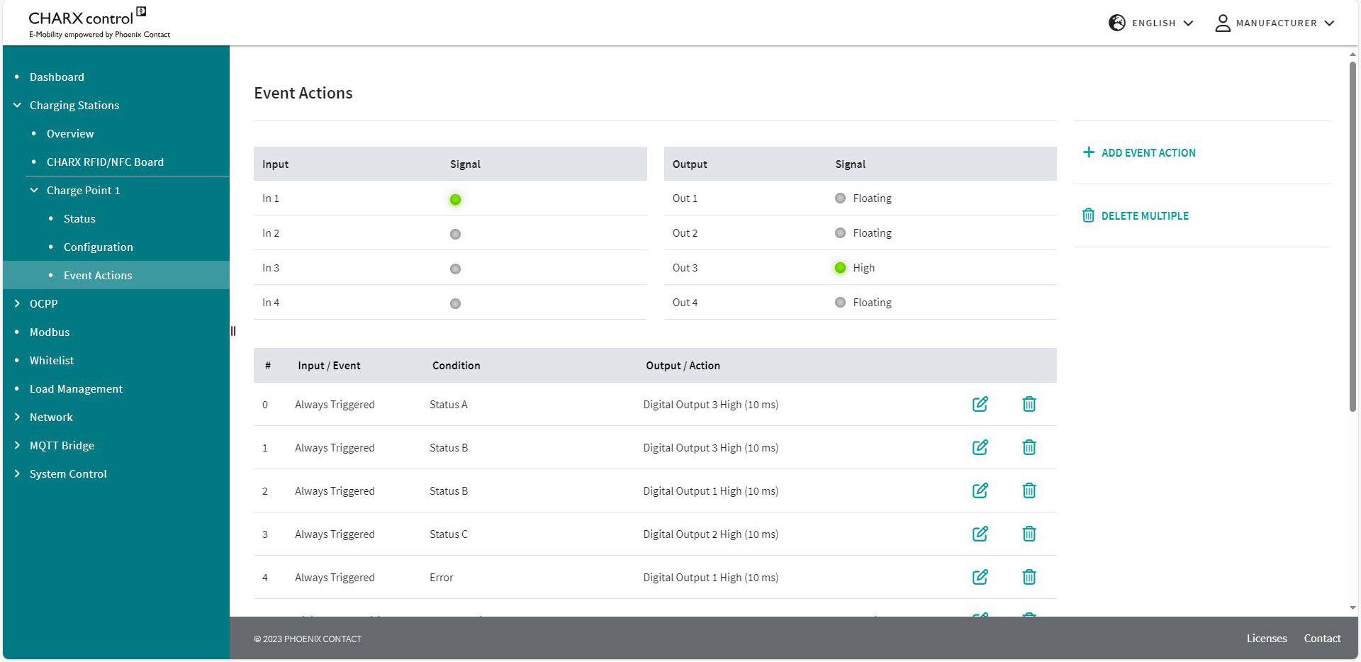
The Event Actions can be triggered internally in the charging controller or also by changes to the input signals. For example, an internal signal could be the rejection of an RFID or the detection of a vehicle that is plugged in. An input signal could be the change of a voltage level at the input or a rising/falling edge. The configured Event Actions are listed below the status of the inputs and outputs. In Figure 5-12, there are three configured Event Actions for controlling the digital outputs.
Each Event Action is associated with an event, which represents the time of the request in the system. Assign an action resulting from the event. You can also request a condition. This is ANDed to the required event. Here, you can add further Event Actions or delete existing Event Actions. The maximum number of configured Event Actions is 32.
Repeated processing of Event Actions
The Event Actions are processed in an endless loop in the specified sequence. This can lead to actions from an Event Action being directly overwritten by a subsequent action and thus not being effective.
Targeted resetting of actions necessary
Depending on the configuration, it may be necessary to cancel actions resulting from Event Actions in a targeted manner when the condition no longer applies. If a condition is not met or a configured event does not occur, this does not automatically mean that the configured action is inverted.
Creating a new Event Action or editing an existing one
Pressing the buttons to create or edit Event Actions opens the Editor. You can select events, actions, and conditions from drop-down fields and make additional settings for them. Figure 5-14 shows the configuration view.
Figure 5-14Configuration view for Event Actions (Event)
Different options can be selected in each column. First, select an input or event that should cause the Event Action in question.
Input or event
The Event Action is only triggered in the case of an event and is ignored for the rest of the time. An event represents a one-time request. If an event is no longer present, the action is not reset.
|
Charging Park | Charging Stations | Charge Point Details | Event Actions |
|
|---|---|
|
Never Triggered |
The event is never triggered, the Event Action is never used. |
|
Always Triggered |
The condition is always queried. An action can be triggered at any time. If a condition changes, this is immediately registered and the Action Timer starts running from the moment of this change. |
|
New Error |
An error is detected. |
|
Error Resolved |
An error no longer occurs. |
|
Digital Input X Rising |
The selected digital input has detected a rising edge. |
|
Digital Input X Falling |
The selected digital input has detected a falling edge. |
|
Plug Connected |
A charging connector has been plugged into the connected charging socket. |
|
Plug Disconnected |
A charging connector has been removed from the connected charging socket. |
|
EV Connected |
A vehicle has been connected to the charging point. |
|
EV Disconnected |
A vehicle has been disconnected from the charging point. |
|
RFID Charge Release |
A charging process has been enabled via an RFID card. |
|
RFID Denied |
An RFID card has been rejected. |
|
Temperature Derating Started |
Curtailment started by the charging controller due to excessively high temperature. |
|
Temperature Derating Ended |
Curtailment has been lifted. |
|
Contactor Failure Detected |
A contactor error has been detected. |
|
Teach-in Successful |
An RFID card has been successfully read and stored in the system. |
|
Teach-out Successful |
An RFID card has been successfully read and removed from the system. |
|
Teach-in Failed |
An RFID card has not been read successfully. |
Condition
Another configuration option is available in the form of conditions that specify the function of Event Actions. Some conditions require further additional settings, which appear below the selection.
Figure 5-15Configuration view for Event Actions (Condition)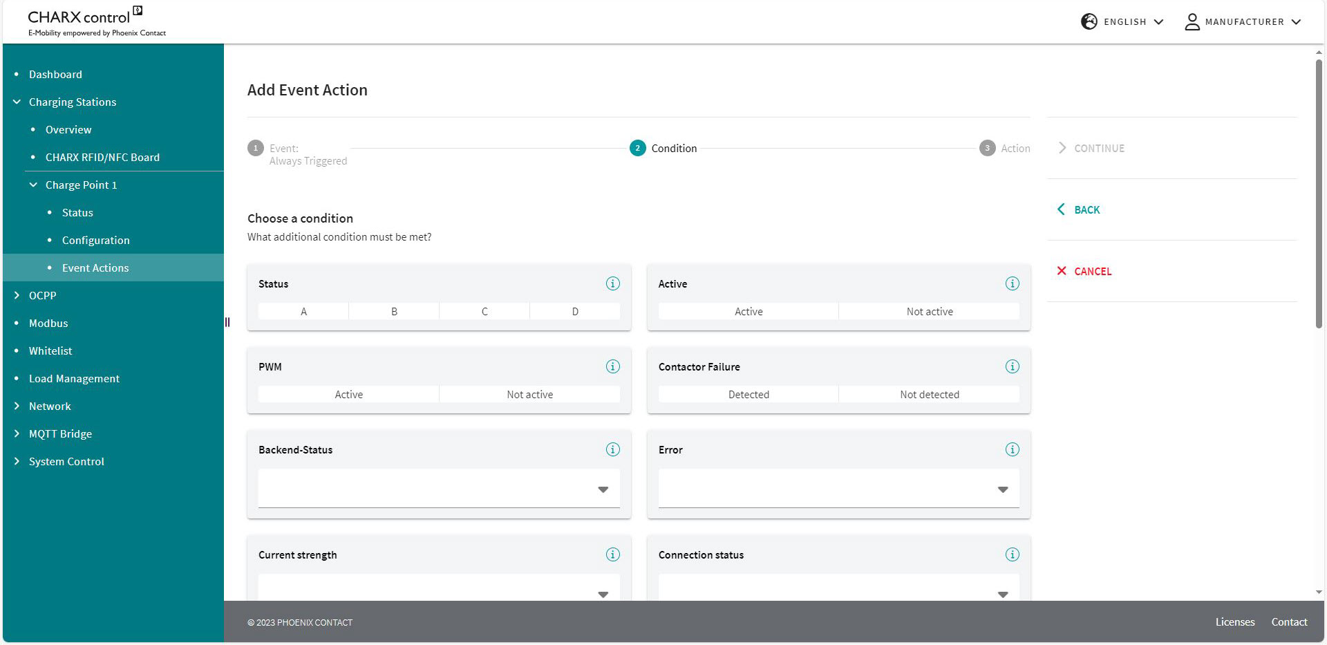
|
Charging Stations | Charge Point | Event Actions |
||
|---|---|---|
|
Condition |
||
|
Never True |
The condition is never met, the action cannot be triggered. |
|
|
Active |
The condition is always met, the action just depends on the event. |
|
|
Digital Input High |
Selection of the input |
The selected input corresponds to the High state. |
|
Digital Input Low |
Selection of the input |
The selected input corresponds to the Low state. |
|
Connector plugged |
A charging connector is inserted into the charging socket. |
|
|
Error |
An error is available in the charging controller. |
|
|
Error Internal |
An internal error has occurred in the charging station. |
|
|
Error External |
An external error has occurred on the vehicle. |
|
|
PP XX A |
The resistance value of the plugged-in charging cable corresponds to the carrying capacity of XX amps. |
|
|
Status A |
The charging point is in status A. |
|
|
Status B |
The charging point is in status B. |
|
|
Status C |
The charging point is in status C. |
|
|
Status D |
The charging point is in status D. |
|
|
EV Connected |
A vehicle is connected. |
|
|
EV not Connected |
There is no vehicle connected. |
|
|
Available |
The charging point is in “Available” status. |
|
|
Preparation |
The charging point is in “Preparing” status. |
|
|
Charging |
The charging point is in “Charging” status. |
|
|
Suspended EV |
The charging point is in “Suspended EV” status. |
|
|
Suspended EVSE |
The charging point is in “Suspended EVSE” status. |
|
|
Finishing |
The charging point is in “Finishing” status. |
|
|
Reserved |
The charging point is in “Reserved” status. |
|
|
Unavailable |
The charging point is in “Unavailable” status. |
|
|
Contactor Failure Detected |
A contactor error has been detected. |
|
|
Last RFID Invalid |
The last read RFID is not valid. |
|
|
PP Under Value |
PP current in amps |
The resistance value of the charging cable is below a specific current value. |
|
PP Over Value |
PP current in amps |
The resistance value of the charging cable is above a specific current value. |
|
Analog Input X Over Value |
Analog input voltage |
The voltage at the selected input X is above the entered value. |
|
Analog Input X Under Value |
Analog input voltage |
The voltage at the selected input X is below the entered value. |
|
Charge Release |
The charging release is present. |
|
|
No Charge Release |
The charging release is not present. |
|
|
External Release |
The charging point is available. |
|
|
No External Release |
The charging point is not available. |
|
|
Temperature Derating |
The charging point is curtailed due to excessively high temperature. |
|
|
No Temperature Derating |
The charging point is not curtailed. |
|
|
Authorization Request ongoing |
Authorization of the RFID card is being requested. |
|
|
No Contactor Failure Detected |
The charging contactor is working properly, a contactor error has not been detected. |
|
|
Current reduced for External Reasons |
The charging current is reduced by an external specification. |
|
|
Current not reduced for External Reasons |
The charging current is not reduced by an external specification. |
|
|
CP PWM on |
The charging point communicates with the vehicle via the PWM signal. The PWM signal is active. |
|
|
CP PWM off |
The charging point does not communicate with the vehicle via the PWM signal. The PWM signal is not active. |
|
|
Backend offline |
No connection to the backend available |
|
|
Backend offline, but charging point available |
No connection to the backend, but charging station available |
|
|
Backend online |
Connection to the backend available |
|
|
Backend online and charging point available |
Connection to the backend and charging station available |
|
You can save the edited Event Actions below the settings or cancel editing.
Output or action
You then select an action for the event. This action can be performed continuously or for a specific time. Continuously means until the action is revoked by another Event Action. To define the time you use an Action Timer, which requires a value to be entered in milliseconds. In this way you can, for example, switch on LEDs for a specific time after the triggering.
Some actions require further additional settings, which appear below the Action Timer if this is the case.
Figure 5-16Configuration view for Event Actions (Action)
|
Charging Stations | Charge Point | Event Actions |
||
|---|---|---|
|
No Action |
There is no action linked to the event. |
|
|
Enable Charging |
Enable Status |
The charging release is switched. Bus controlled: The charging release is issued and withdrawn via Modbus. Enable: The charging release is set. Disable: The charging release is withdrawn. |
|
Lock Connector |
The actuator moves to the locking position in the charging socket. |
|
|
Unlock Connector |
The actuator moves to the unlocking position in the charging socket. |
|
|
Digital Output X Low |
The digital output goes to 0 V. |
|
|
Digital Output X High |
The digital output goes to 12 V. |
|
|
Digital Output X Floating |
The digital output has no potential. |
|
|
Digital Output X Flashing High |
Flashing PWM |
The digital output flashes and assumes 12 V for a specific period. The entry in Flashing PWM affects the setting of the percentage value for how long the output is set to High in relation to the total period length. Period length = 2 s. |
|
Digital Output X Flashing Low |
Flashing PWM |
The digital output flashes and assumes 0 V for a specific period. The entry in Flashing PWM affects the setting of the percentage value for how long the output is set to Low in relation to the total period length. Period length = 2 s. |
|
Digital Output X Pulsatile Low |
The output pulsates and assumes the voltage level of 0 V, increasing and decreasing in time. |
|
|
Digital Output X Buscontrolled |
The output can be controlled via internal or external software. |
|
|
Reduce maximum charging current |
Reduction maximum current |
The set current at the charging point is reduced. The set current should be reduced to this set value in amps. |
|
External Release |
Enable Status |
The availability of the charging point is switched. Bus controlled: The availability is set via the Modbus registers. Enable: The charging point is set to available. Disable: The charging point is set to not available. Optionally, a freely definable error description can be sent to an OCPP backend. The event “Digital Input X Rising/Falling” and the condition “Always True” are required for this. If “EmergencyStop” is entered as an error description, the StopReason “EmergencyStop” is transmitted to the backend. |

Action Timer
If an action should cease immediately when a condition changes, set the Action Timer to a very low value (e.g., 10 ms).
If an action should not cease automatically when a condition changes, set the Action Timer to 0 ms.
The action remains until it is manually reset (e.g., by another Event Action). If the one-time occurrence of a short event is to be followed by a longer action, set the Action Timer to the duration of this action.
For example: The RFID card is rejected via OCPP. Then a flashing red LED appears for five seconds.
Examples of Event Action configuration
Event Actions for external specifications
|
Input |
1 |
2 |
3 |
|---|---|---|---|
|
Description |
Charging release via a digital input as a button when a car is connected. |
Shutdown of the charging point by an input. |
Current reduction to 16 A by an input. |
|
Event |
Digital Input 1 Rising |
Always Triggered |
Always Triggered |
|
Action |
Create Charging Release |
External Release |
Reduce maximum charging current |
|
Action Timer |
0 ms |
1000 ms |
10 ms |
|
Reduce maximum Current: 16 A |
|||
|
Condition |
Status B |
Digital Input High: “Low” |
Digital Input High: “High” |
Event Action configuration for the LED charging socket
Connection to the first digital output: Red
|
Status |
Charging point error |
Vehicle error |
Invalid RFID |
Reserved charging point |
Vehicle rejected |
|---|---|---|---|---|---|
|
Description |
In the event of a charging point error, the red LED is steady on. |
In the event of a vehicle error, the red LED flashes. |
In the event of a rejected RFID, the LED flashes for 3 seconds. |
If the charging point is reserved, the LEDs light up yellow. |
If there is no charging release for the charging point, the LEDs flash yellow. |
|
Event |
Always Triggered |
Always Triggered |
RFID Denied |
Always Triggered |
Always Triggered |
|
Action |
Digital Output 1 High |
Digital Output 1 Flashing High |
Digital Output 1 Flashing High |
Digital Output 1 High |
Digital Output 1 Flashing High |
|
Action Timer |
10 ms |
10 ms |
3000 ms |
10 ms |
10 ms |
|
Condition |
Error External |
Error External |
Always True |
Reserved |
Suspended EVSE |
Connection to the second digital output: Green
|
Status |
Available |
Reserved charging point |
Vehicle rejected |
|---|---|---|---|
|
Description |
If the charging point is available, the green LED lights up. |
If the charging point is reserved, the LEDs light up yellow. |
If there is no charging release for the charging point, the LEDs flash yellow. |
|
Event |
Always Triggered |
Always Triggered |
Always Triggered |
|
Action |
Digital Output 2 High |
Digital Output 2 High |
Digital Output 2 Flashing High |
|
Action Timer |
10 ms |
10 ms |
10 ms |
|
Condition |
Available |
Reserved |
Suspended EVSE |
Connection to the third digital output: Blue
|
Status |
Preparation |
Charge |
Vehicle paused |
|---|---|---|---|
|
Description |
If charging is started, the blue LED is steady on. |
When the vehicle is charging, the blue LED flashes. |
If the vehicle is fully charged or rejects charging, the blue LED flashes slowly. |
|
Event |
Always Triggered |
Always Triggered |
Always Triggered |
|
Action |
Digital Output 3 High |
Digital Output 3 Flashing High; Flashing PWM 50% |
Digital Output 3 Flashing High; Flashing PWM 80% |
|
Action Timer |
10 ms |
10 ms |
10 ms |
|
Condition |
Preparing |
Charging |
Suspended EV |
Connection to the fourth digital input
|
Input |
4 |
4 |
|---|---|---|
|
Description |
Stop charging process when emergency switching off switch is pressed |
Continue charging process when emergency switching off switch is reset |
|
Event |
Digital Input 4 Rising |
Digital Input 4 Falling |
|
Action |
External Release |
External Release |
|
Action Timer |
Permanent |
Permanent |
|
Enable Status |
Disable Message to OCPP backend: EmergencyStop |
Bus-controlled |
|
Condition |
Always Active |
Always Active |
Ensure additional safety relay or contactor
This Event Action configuration is only used to transmit the correct StopReason to the OCPP backend. In the event of an emergency shutdown, you must also ensure that the power supply of the charging socket or the charging cable is interrupted by a contactor or safety relay.
WBM – OCPP
In the “WBM/OCPP” area, you can view the current status of the OCPP configuration, configure the communication parameters for the backend, and make settings regarding operation.
The charging point must be configured as an OCPP charging point (“Allow Charging”, “By OCPP:” under “Charging Stations | Charge Point | Create configuration”).
OCPP Status Information
Figure 5-17Status indicator for OCPP communication
On the Status page, you can see the current connection status for the OCPP management system.
–Green indicates that a connection exists.
–Red indicates that no connection exists. If a connection exists, check the settings for the modem or the Ethernet interface in the System Control.
It also shows the status of the charging points controlled via the backend. In addition, you can keep track of the last 50 messages between the charging controller and the backend.
Menu does not show any OCPP charging points
If the menu does not show any or not all charging points, check the “Allow Charging” area in the charging point configuration. Check whether all charging points controlled via OCPP have been configured for release via OCPP and a valid connector ID has been assigned in each case.
The headers of the messages in the list contain the last messages that were exchanged with the OCPP backend:
–Time stamp of transmission
–Message type (2 = CALL, 3 = CALL RESULT)
–Message ID (unique ID of the message, used by CALL and the associated CALL RESULT)
–Action (OCPP instruction/message)
–Payload with the user data belonging to the action
Additional OCPP messages available in the log files
If necessary, you can refer back to previous messages in the log file, which can be downloaded via System Control/Log Files.
OCPP settings
In the “OCPP settings” area, you can enter the configuration parameters required to operate the charging station on a server.
If the parameters are changed, the OCPP agent must be restarted, for example, via the “RESTART OCPP SERVICE” button.
Make additional settings in the charging point configuration
See “Charging Stations/Charge Point/Configuration” on page 88.
Figure 5-18Configuration of the OCPP connection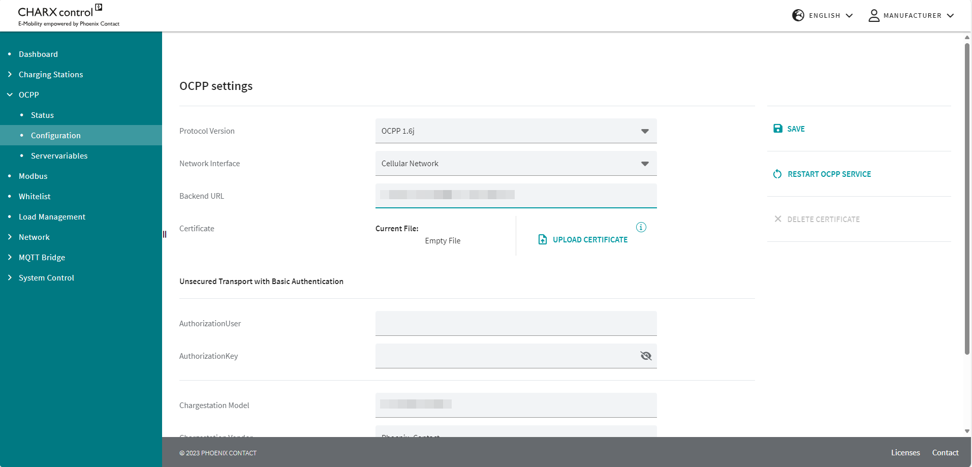
|
OCPP | Configuration |
|
|---|---|
|
OCPP settings |
|
|
Protocol Version |
Selection of the OCPP protocol standard; only OCPP 1.6J can be selected at present. |
|
Network Interface |
Selection field to specify whether connection to the backend should be via cellular communication (ppp0), WLAN (wlan0), or Ethernet (eth0). |
|
Backend URL |
URL/IP address to access the backend with unique charge box ID (provided by the operator). Example: ws://testserver.net:8080/chargeboxid |
|
AuthorizationUser |
User name for the backend login in “Basic Authentication” operating mode in accordance with the OCPP Security White Paper Usually, the charge box ID of the backend URL is used. The parameter can also be modified as an OCPP ConfigurationKey. |
|
AuthorizationKey |
Password for the backend login in “Basic Authentication” operating mode in accordance with the OCPP Security White Paper. The parameter can also be modified as an OCPP ConfigurationKey. |
|
Upload Certificate |
Button that can be used to create a certificate for a secure connection (wss://...) to the backend. This button is only visible if the URL starts with “wss://...”. After the upload, the certificate must be permanently saved on the charging controller by means of the Save button in order to use it. |
|
Delete Certificate |
Button to remove a saved certificate. This button is only visible if a corresponding certificate is present on the controller. |
|
Charging Station Model |
Manufacturer’s model designation for the charging station |
|
Charging Station Manufacturer |
Manufacturer of the charging station |
|
Charging Station Serial Number |
Charging station serial number assigned by the manufacturer (optional) |
|
SAVE |
Button to save the modified configuration |
|
RESTART OCPP SERVICE |
OCPP software restart, recommended after making changes to the configuration |
|
The “OCPP Servervariables” area provides you with an overview and some options for entering configuration keys for operating the charging station at the backend. A distinction is made here between variables that are defined in the OCPP communication protocol and variables that are specific to the CHARX control charging controller. Variables that have the status “ReadOnly = False” can be modified from the backend via a ChangeConfiguration as well as via the web-based management. Variables with the status “ReadOnly = True” are displayed, but cannot be modified. Information on OCPP standard configuration keys Detailed information on the standardized OCPP configuration keys is available from the Open Charge Alliance (www.openchargealliance.org). |
|
|
CHARX Variables | Servervariables |
|
|---|---|
|
ServiceRestart |
If this button is enabled, the occupied charging points are registered under the service RFID at the backend after a restart. |
|
ServiceUID |
RFID with which vehicles can be registered when the charging station is restarted, if the restart service is enabled. |
|
FreeMode |
If this button is enabled, charging processes are automatically authorized at the backend on plug-in. |
|
FreeModeUID |
RFID with which vehicles are authorized when Freemode is enabled. |
|
EVDiscardTimeOut |
Time interval [s] after which a read UID is discarded if no vehicle is connected. |
|
ForceUpdate |
Software update is installed even if charging processes are still active. |
|
GlobalMaxCurrent |
Maximum total current [A] of all charging points in the system. |
|
LogLevel |
–DEBUG (high level of log detail) –INFO (low level of log detail) |
|
MaxCurrent |
Maximum charging current [A] at the individual charging points. |
|
ModemRestartTimeout |
Time interval [s] after which the modem is restarted in the event of unsuccessful connection. |
|
NewBackendURL |
Text string for transferring the backend connection to a new URL. |
|
PreUnavailabilityForUpdate |
Time interval [s] in which the charging station is set to status F before an update is performed. |
|
RFIDByteOrder |
Switch-over of the byte order of the RFID card (Little Endian/Big Endian). |
|
RFIDCharacterOrder |
Switch-over of the UID character order to 16-bit data words. |
|
WebSocketPingTimeout |
Time interval after which the web socket connection is re-established in the absence of a response. |
|
AllowTimeSyncDuringSession |
System time is synchronized, even during an active charging process. |
|
AvailabilityOnlyWhenTimeSynchronized |
Charging station is only available when the system time is synchronized. |
|
EichrechtAdminList |
UIDs for administrator access on the CHARX display. |
|
MessageAtKeyTransfer |
Configurable value within the DataTransfer message for transmitting the public key. |
|
MeterValuesSignatureContexts |
Not used in the current software. |
|
PresentingRFIDEndCharging |
Charging process is ended and lock is opened when the same RFID card is read again. |
|
SignedDataFormat |
Format of the data sent with the StopTransaction 0 = OCMF format 2 = Measuring device-specific format |
|
StopTransactionSignatureContexts |
Not used in the current software. |
|
StopTransactionSignatureFormat |
Not used in the current software. |
|
VendorAtKeyTransfer |
Configurable value within the DataTransfer message for transmitting the public key. |
|
AuthorizationUser |
User name for the backend login in “Basic Authentication” operating mode in accordance with the OCPP Security White Paper |
|
AuthorizationKey |
Password for the backend login in “Basic Authentication” operating mode in accordance with the OCPP Security White Paper. The value cannot be requested from the backend: the value “****” is sent back to a GetConfiguration. |
Modbus
In this area, you can specify the Modbus start addresses for the various charging points.
Figure 5-19Modbus overview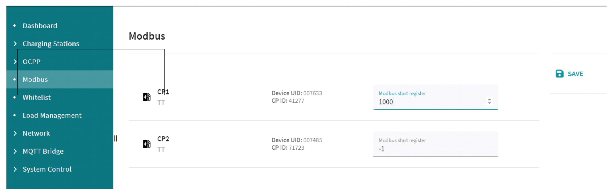
Valid start addresses are integer multiples of 1000 in the range from 1000 to 48000.
If the start address is “-1”, the final start address is assigned automatically after a restart. This means that charging points can be accessed under a new start address after another restart. Manually assigned registers do not change and “mixed operation” is not possible. If at least one start register is assigned manually, further controllers can only be accessed via Modbus if they are also assigned to manual start registers.
For a detailed description, please refer to the tables in the appendix “Modbus communication and register overview” on page 158.
WBM – Whitelist
Figure 5-20Local whitelist
Each charging park has an optional whitelist to which you can add charging authorizations. The whitelist for Variable „Product Area 3xxx“ ist nicht definiert modules are limited to 500 entries. Different actions can be performed.
In charging parks that support charging controllers with ISO 15118 communication, you can add both the RFID UIDs and the EVCC ID of the vehicle to the whitelist. This enables the automatic detection and release of the charging process if a vehicle supports communication in accordance with ISO 15118.
You can export the local whitelist. On export, you save the user list in the Download area in the form of a csv file.
You can also import the whitelist. There are two options for this. You can add the imported user releases to the whitelist. Use the “Add From Import” field for this. You can also overwrite the whitelist with a file. Use the “Replace with Import” field for this.
In addition, you can add new user releases individually via the “+ NEW ENTRY” button.
The whitelist is displayed below the buttons. You can delete or edit an entry on the right of the screen.
WBM – Load Management
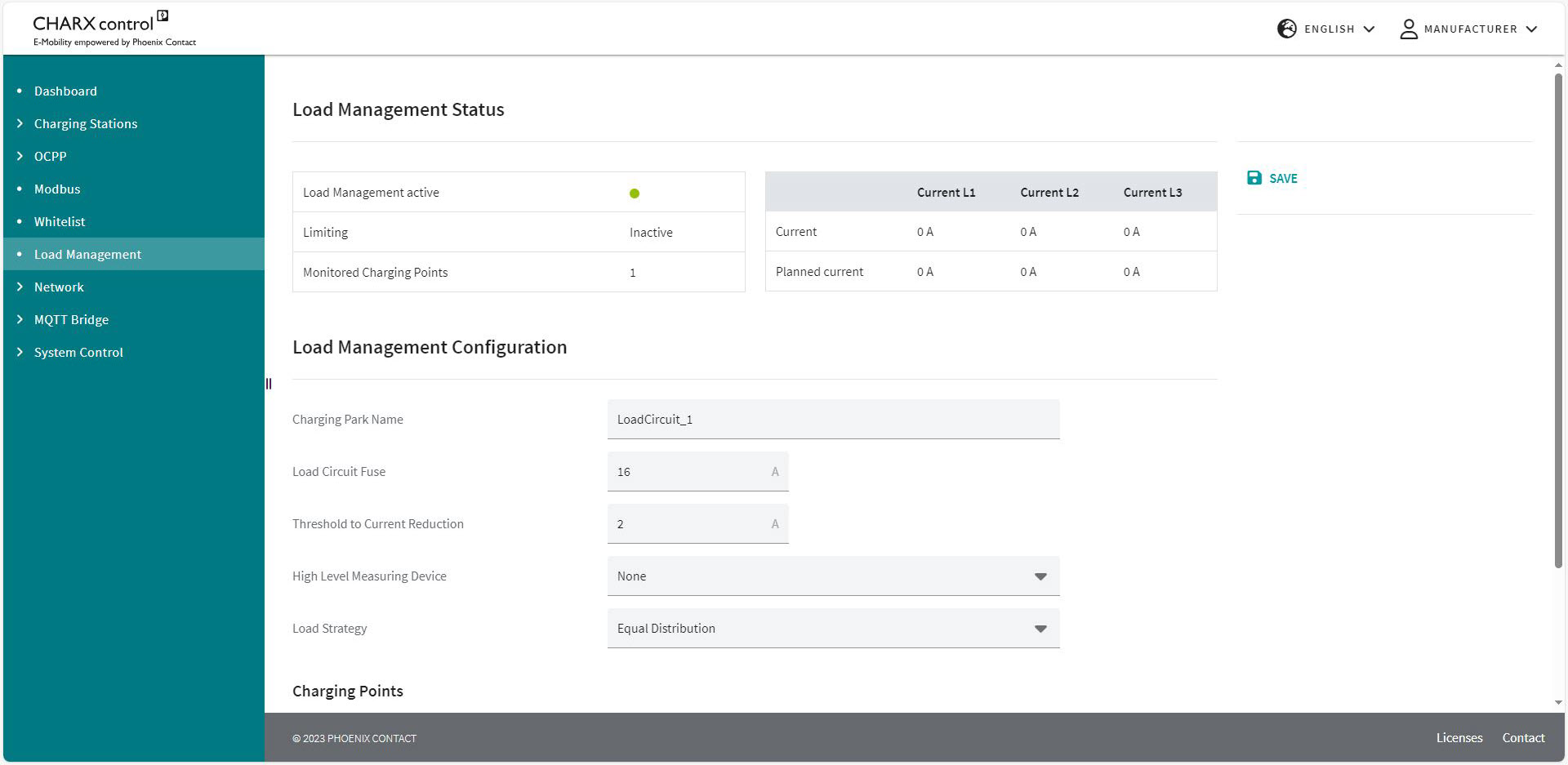
The web page for load management in the charging park is divided into three parts. The current status of load management is shown at the top of the page. Below it, you can define configurations and add charging points to the load management.
Load Management
|
Load Management |
|
|---|---|
|
Load Management Status |
|
|
Load Management active |
A color indicator signals whether the load management agent in the charging controller is running. Green: The load management agent is running. Red: The load management agent is not running. |
|
Limiting |
Shows whether the charging current is being limited. In this case, the load circuit fuse value is below the current required by the electric vehicles. |
|
Monitored Charging Points |
Shows how many charging points are being monitored by the load management. |
|
Current |
Shows the total charging currents at all monitored charging points. |
|
Planned current |
Shows the planned total currents at all monitored charging points. The planned currents reflect the settings for the vehicles. The actual current is usually slightly below this set current. There is no need for action here because the cars determine the current with a safety margin from the set value. |
|
Load Management Configuration |
|
|
Charging Park Name |
The name of the charging park can be specified. |
|
Load Circuit Fuse |
The fuse value of the load circuit in amps. The fuse value applies to all connected charging points. See Figure 2-10 “Load management with multiple charging stations and charging points” (fuse B). This value determines the maximum amount of current that may be obtained by all connected charging points. |
|
Threshold to |
Defines the maximum possible deviation of the charging current of a connected car from the load management current specification in amps; if this threshold is exceeded, the current specification is reduced. Example: Current specification by load management: 16 A Actual charging current: 13 A Threshold to current reduction: 4 A Current specification is not reduced. Threshold to current reduction: 2 A Current specification is reduced by load management. |
|
If other loads are connected to the same fuse as the charging park, a higher-level measuring device can record the total current. This ensures that the load circuit fuse value is respected, even if the charging points are significantly below this current value. The measuring device is configured via the connection type. –None: No higher-level measuring device connected. –TCP/IP connection: The higher-level measuring device is connected via a network connection. –RS-485 connection: The higher-level measuring device is connected to the charging interface of a charging controller via the RS-485 connection. Only energy measuring devices of the same type can be connected to an RS-485 interface. The Modbus address of the higher-level measuring device must be set to “Default setting +1”. |
|
|
Configured |
The charging point to which the measuring device is connected is selected here. Only available when “RS-485 connection” is selected. |
|
Higher Level |
The fuse value of the feed-in in amps. The fuse value applies to all charging points and loads connected to the feed-in. This fuse is monitored by the higher-level measuring device. See Figure 2-10 “Load management with multiple charging stations and charging points” (fuse A). This value determines the maximum amount of current that may be obtained by all connected charging points and additional loads. |
|
IP Address |
The IP address of the measuring device is entered here. Only available when “TCP/IP connection” is selected. |
|
Energy Measuring Device Type |
Here, you can select the energy measuring device type for the measuring device configured via the IP address. –Phoenix Contact EEM377 EEM-EM377, 2908590 –Phoenix Contact MA370 EEM-MA370-R, 2907980 EEM-MA370-24DC, 1127059 EEM-MA370, 2907983 |
|
Load Strategy |
Here, you select the potential charging strategy. Equal distribution: All charging points receive the same settings. The charging points are not prioritized. |
|
Charging Management Charging Points |
|
|
Here you can add charging points to the load management. Selected charging points are assigned to the load circuit. |
|
In addition to the chosen charging strategy, other optimizations are made that have no priority on a specific charging point.
–If a setting exceeds the desired charging current of a vehicle, the remaining charging current will be distributed to the other charging points. This redistribution is checked at regular intervals and repeated.
–The redistribution is performed with no phase delay. In the event of an uneven distribution, current that is left on a phase will be taken into consideration in the calculation and assigned elsewhere in the redistribution. This ensures that the maximum current is distributed to one-, two-, and three-phase vehicles.
–Reducing the charging current settings may not be enough to charge below the load circuit fuse value. This can happen due to the parking lot being busy, for example. In this case, load management disconnects individual vehicles. The vehicles with the longest charging duration are disconnected first. These can be connected again during a subsequent redistribution.
WBM – Network
Network/Ethernet
The settings for the ETH0 Ethernet interface are made via the “Network” area. The corresponding status data is displayed. Login as “Operator” or “Manufacturer” is required for this.
No configuration option for the ETH1 interface
The ETH1 interface is intended to connect additional charging controllers in a daisy chain network or star network. Configuration is performed automatically by connecting charging controllers together and setting the operating mode to “Client”. Further configuration settings are not necessary or intended.
Figure 5-22Network configuration of the ETH0 interface
|
Network |
|
|---|---|
|
Network Configuration |
|
|
IPv4 Address |
Display field for the current IPv4 network address of the charging controller (specified by DHCP or set manually) |
|
Broadcast Address |
Display field for the broadcast address that can be used to reach all devices in the network (specified by DHCP server) |
|
IPv6 Address |
Display field for the current IPv6 network address of the charging controller (specified by DHCP) |
|
Received (Rx) |
Data volume received since the charging controller was started |
|
Transmitted (Tx) |
Data volume transmitted since the charging controller was started |
|
MAC Address |
Factory-set MAC address of the charging controller |
|
Automatic Assignment (DHCP) |
Button to enable automatic IP address assignment by the external DHCP server |
|
No Gateway |
Field is visible once DHCP has been selected. When the selection field is enabled, no gateway is entered. Software applications on the charging controller cannot access the Internet via ETH0 in this case. When the selection field is not enabled, the gateway specified by the DHCP server is used. |
|
IP Address |
Input field for specifying the IPv4 address of the charging controller when DHCP address assignment is disabled |
|
Subnet Mask |
Input field for the subnet mask of the charging controller. This subnet mask is used if there is no active DHCP service. (Default: 255.255.255.0) |
|
Gateway |
Input field for the IP address of the default gateway. This IP address is used if there is no active DHCP service. |
|
Host Name |
Input field for the host name of the charging controller. (Default: ev3000) |
|
DNS Name Servers |
Input field for the IP addresses of the DNS name servers, maximum 3 entries |
|
SAVE |
Button to transfer the network configuration |
IP address and gateway must not be in the range 192.168.4.X and 192.168.5.X. These are reserved for the USB-C connection and the internal server-client connection.
When using the Ethernet interface eth0 and the WLAN interface simultaneously, make sure that the corresponding IP addresses are not in the same subnetwork.
WLAN Settings
Use the “WLAN Settings” area to set the settings for the “Access Point” and “Infrastructure” operating modes.
Figure 5-23“Access Point” operating mode settings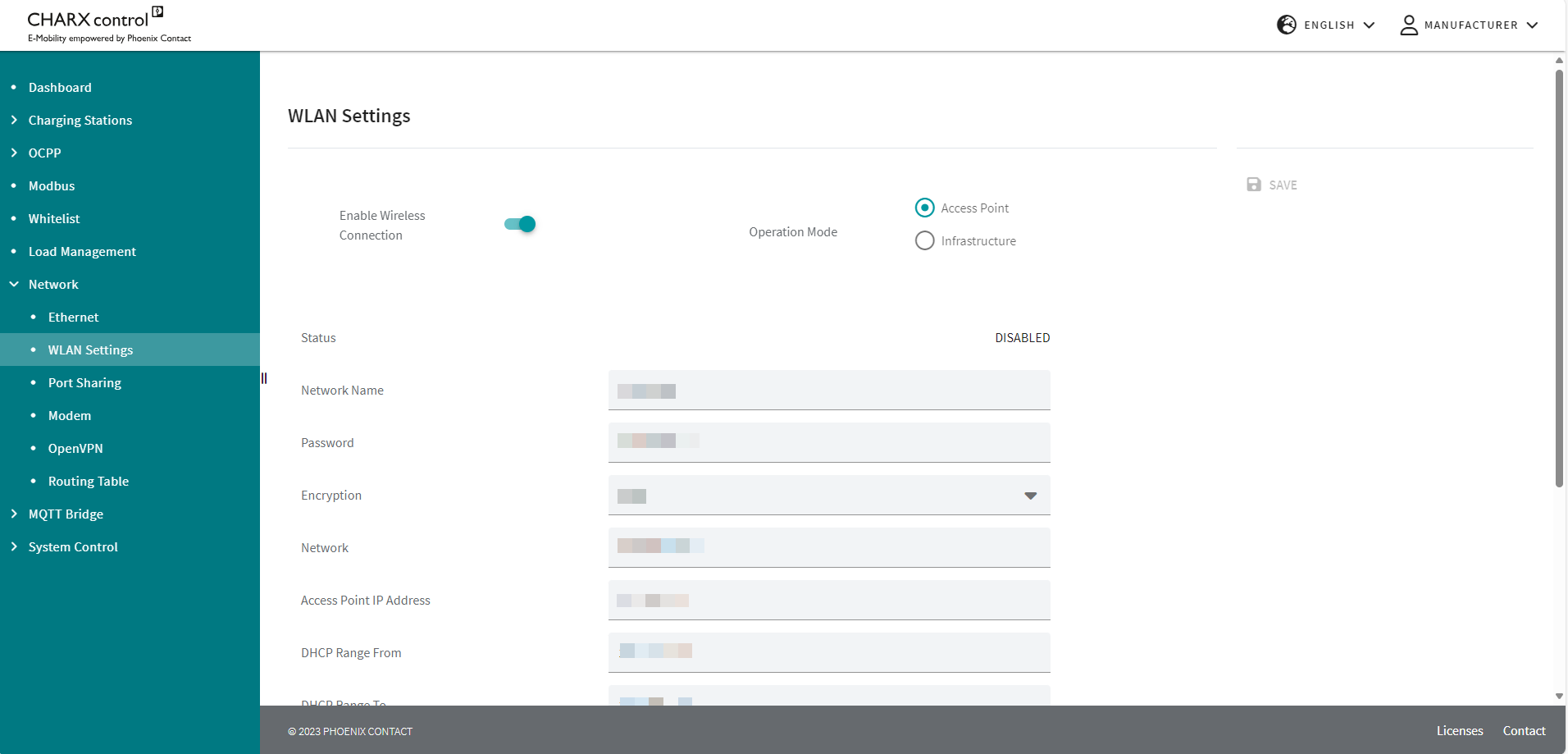
|
WLAN Settings |
|
|---|---|
|
Enable Wireless Connection |
Button for activating the USB dongle for WLAN |
|
Operation Mode |
Button for selecting the operating mode Access Point: The charging controller creates a WLAN access point that can be used to connect WLAN-capable devices. Infrastructure: The charging controller can connect to an existing WLAN network. |
|
SAVE |
Button to save the current configuration |
|
Access Point operating mode |
|
|
Network Name |
Input field for specifying the name of the WLAN network under which it is displayed by other devices |
|
Password |
Input field for specifying the password for connecting to the WLAN network |
|
Encryption |
Network encryption selection field |
|
Network |
Specification of IP addresses in the WLAN network, IP address/subnet mask format (e.g., 192.168.0.1/24) |
|
Access Point IP Address |
IP address of the charging controller in the WLAN network |
|
DHCP Range From |
Input field for specifying the IP addresses that are assigned to the network devices (lower limit) |
|
DHCP Range To |
Input field for specifying the IP addresses that are assigned to the network devices (upper limit) |
|
Band |
Frequency band selection field |
|
Country Code |
Selection of the regulatory country in which the WLAN network is operated. |
|
Timeout in seconds |
Time after restart in which the access point is deactivated if no device connects to this network (0 = no deactivation) |
Figure 5-24“Infrastructure” operating mode settings
|
WLAN Settings |
|
|---|---|
|
Infrastructure operating mode |
|
|
Network |
Selection field of available WLAN networks |
|
REFRESH |
Button to update the list of available WLAN networks When it is updated, existing WLAN connections may be disconnected. |
|
Password |
Input field for the password for the selected WLAN network |
|
Country Code |
Selection of the regulatory country in which the WLAN network is operated. |
|
SSID |
Currently selected/stored WLAN network |
|
Status |
Connection status to the selected WLAN network |
|
Current IP |
IP address of the charging controller in the WLAN network |
|
Signal Strength |
Signal strength of the current WLAN network |
|
Gateway |
Gateway IP address for the WLAN network |
|
DNS |
IP address of the domain name server for the WLAN network |
When using the Ethernet interface eth0 and the WLAN interface simultaneously, make sure that the respective IP addresses are stored in different subnetworks.
Network/Port Sharing
In the “Network/Port Sharing” area, you can block individual incoming ports and in this way prevent external network access.
Figure 5-25Port Sharing.jpg)
NOTE: Close ports that are not required
To protect the charging controller against unauthorized access, close ports that are not required.
Ports that may be used by the charging controller software are specified in the web-based management.
|
System Control | Port Sharing |
|
|---|---|
|
Incoming TCP/UDP Ports |
|
|
22 |
SSH Access |
|
80 |
HTTP Access |
|
81 |
Custom Website |
|
443 |
HTTPS Access |
|
502 |
MODBUS Server (for Modbus/TCP requests) |
|
1603 |
Frame data for load management |
|
1883 |
MQTT |
|
2106 |
OCPP Remote |
|
5000 |
Web Server |
|
5353 |
mDNS (multicast DNS) |
|
5555 |
Jupicore accesses |
|
9502 |
MODBUS Client Configuration |
NOTE: Web page requires Jupicore access via port 5555
Port 5555 must be open in order to use the full scope of functions of the web-based management. If you use the WBM only occasionally, you can open this port temporarily via the WBM as required.
You can add further ports that are required for software implemented by the customer via the WBM, this is done via the “New Port” input field and “ADD PORT” button. This function can be used for incoming as well as outgoing ports.
Network/Modem
In the “Network/Modem” area, you can configure the cellular interface and acquire current status data. Login as “Operator” or “Manufacturer” is required for this.
Figure 5-26Modem status and configuration data
|
Network | Modem |
|
|---|---|
|
Modem Status |
|
|
Providers |
Operator of the network to which the charging controller is currently connected |
|
APN |
Access point name of the currently active access point to the data network |
|
Registration Status |
Not registered/Not searching, Registered, Searching, Registration denied, Unknown |
|
Roaming Status |
Shows whether the charging controller is logged into the home network or another network (HOME/ROAMING) |
|
Signal (Quality) |
Current signal quality of the cellular connection |
|
Signal (RSSI) |
Displays the RSSI value, the reception strength (power level) of the cellular signal in dBm |
|
Signal (CQI) |
Displays the CQI value, the channel quality of the cellular connection |
|
Radio Technology |
Currently active wireless technology (LTE, GSM) |
|
IMSI |
Unique ID of the cellular communication subscriber |
|
ICCID |
Unique ID of the SIM card used |
|
MSISDN |
MSISDN is the unique calling number of the SIM card used |
|
Status of the SIM card used: READY, SIM PIN, SIM PUK, SIM not inserted, SIM PIN required, SIM PUK required, SIM failure, SIM busy, SIM wrong, Incorrect password, No network service |
|
|
Modem Configuration |
|
|
Service active |
Button to activate the integrated modem |
|
SIM Pin |
Input field for the SIM card used, provided by the cellular provider |
|
APN |
Input field for the APN (access point), provided by the cellular provider |
|
Use credentials |
Input field when you require a user name and password for access to the APN, specified by the cellular provider |
|
User |
User name for access to the APN, provided by the cellular provider |
|
Password |
Password for access to the APN, provided by the cellular provider |
|
Default Route |
If this selection field is enabled, the cellular connection is used as the default route for data traffic. In this case, an explicit route via ETH0 or ppp0 (cellular communication) is not specified in the user program. |
|
Prefer Modem over ETH0 |
If another interface is selected as the default route, the cellular interface will be selected preferentially via the selection field (smaller metric) |
|
SAVE |
Button to transfer the configuration data to the charging controller |
|
RESTART MODEM SERVICE |
Restarts the modem. |
|
TEST MODEM |
Sends a ping to the entered network address. |
|
Cellular Network Connection |
|
|
Connection Status |
Status of the connection to the target system (Disconnected, Connecting, Connected) |
|
IP Address |
IP address of the charging controller in the cellular network |
|
Primary DNS Server |
IP address of the primary DNS server in the cellular network |
|
Secondary DNS Server |
IP address of the secondary DNS server in the cellular network |
|
RX Bytes |
Amount of data sent since the last boot process (bytes) |
|
TX Bytes |
Amount of data received since the last boot process (bytes) |
|
Device Information |
|
|
IMEI |
International Mobile Equipment Identity, the unique ID of the integrated cellular modem |
|
Manufacturers |
Manufacturer of the integrated cellular modem |
|
Model |
Model of the integrated cellular modem |
|
Revision |
Current revision of the integrated cellular modem |
Network/OpenVPN
In the “OpenVPN” area, the connection to an OpenVPN server can be configured, a test connection can be established, and the connection status can be displayed.
Figure 5-27OpenVPN connection status and configuration data
NOTE: Configuration of the VPN connection
You can configure the VPN connection either by manually entering the configuration parameters in the input field or by importing a complete configuration file. When entered manually, all information remains visible and editable, including the certificates. Manual entry is recommended for test purposes only.
For regular operation, it is recommended that the final configuration file is transferred to the charging controller via file import. A configuration file that has been transferred via file import cannot be read or edited via the web-based management. It is protected against external access.
To do so, delete the manually entered configuration parameters and import the desired configuration via the “IMPORT CONFIGURATION” button.
|
Network/OpenVPN |
|
|---|---|
|
OpenVPN Status |
|
|
VPN Status |
Displays the connection status to the OpenVPN server: “connected”/“not connected” |
|
OpenVPN Server IP |
Displays the IP address of the OpenVPN server from the OpenVPN configuration file (only displayed if the IP address is stored in the configuration file, no DNS resolution is performed) |
|
OpenVPN Private IP |
Displays the IP address assigned to the charging controller in the OpenVPN network by the VPN server |
|
Connected to Server since |
Displays the duration of the current connection to the OpenVPN server |
|
Configuration options |
COPY/PASTE CONFIGURATION: You can insert and edit a configuration manually by selecting this option. The configuration data remains visible. IMPORT CONFIGURATION: A dialog box for selecting the configuration to be applied opens. After the configuration file has been imported, the file name is displayed. The contents are not visible or editable. |
|
COPY/PASTE CONFIGURATION |
|
|
Input field |
Input field in which the content of the configuration file can be copied by the OpenVPN server. The configuration file is typically created by the OpenVPN server. The “dev-type” configuration parameter must be of the type “do”. If it is specified as the type “tap”, an automatic change takes place in the background. If necessary, insert the “route-noexec” parameter as an additional line in the configuration file to prevent automatic changes to the IP routing when OpenVPN is activated. You can configure IP routing via the WBM if necessary (“Routing table” on page 122). |
|
Activation mode |
Permanently Activated: The connection to the VPN server is established when the charging controller is started. Permanently Deactivated: The connection to the VPN server is not established. On Request: The establishment of a connection to the OpenVPN server is activated via an external signal. In the current software version, the “On Request” activation takes place via an MQTT topic from a remote MQTT broker <topic_prefix>/<device_type>/<device_id>/command |
|
IMPORT CONFIGURATION |
|
|
IMPORT CONFIGURATION |
A dialog box for selecting the configuration to be used opens. After the configuration file has been imported, the file name is displayed. The contents are not visible or editable. |
|
SAVE |
Saves the current configuration. If the activation mode is set to “Permanently Activated”, the OpenVPN connection is established. |
|
TEST |
The current configuration parameters are used to attempt to establish an OpenVPN connection. It is not necessary to save the configuration data. After the test is completed, an information window appears with the connection log, which can be used for troubleshooting. |
|
DELETE CONFIGURATION |
Deletes the current OpenVPN configuration. |


Routing table
The routing table can be used to specify via which gateway and interface a specified IP address or IP address range can be reached by the controller. The table contains both the routes created automatically by the Linux system and the manually added routes.
Note that domain name resolution restrictions can apply and possibly not all network interfaces can be used in parallel if using DNS servers that are not equivalent.
Figure 5-28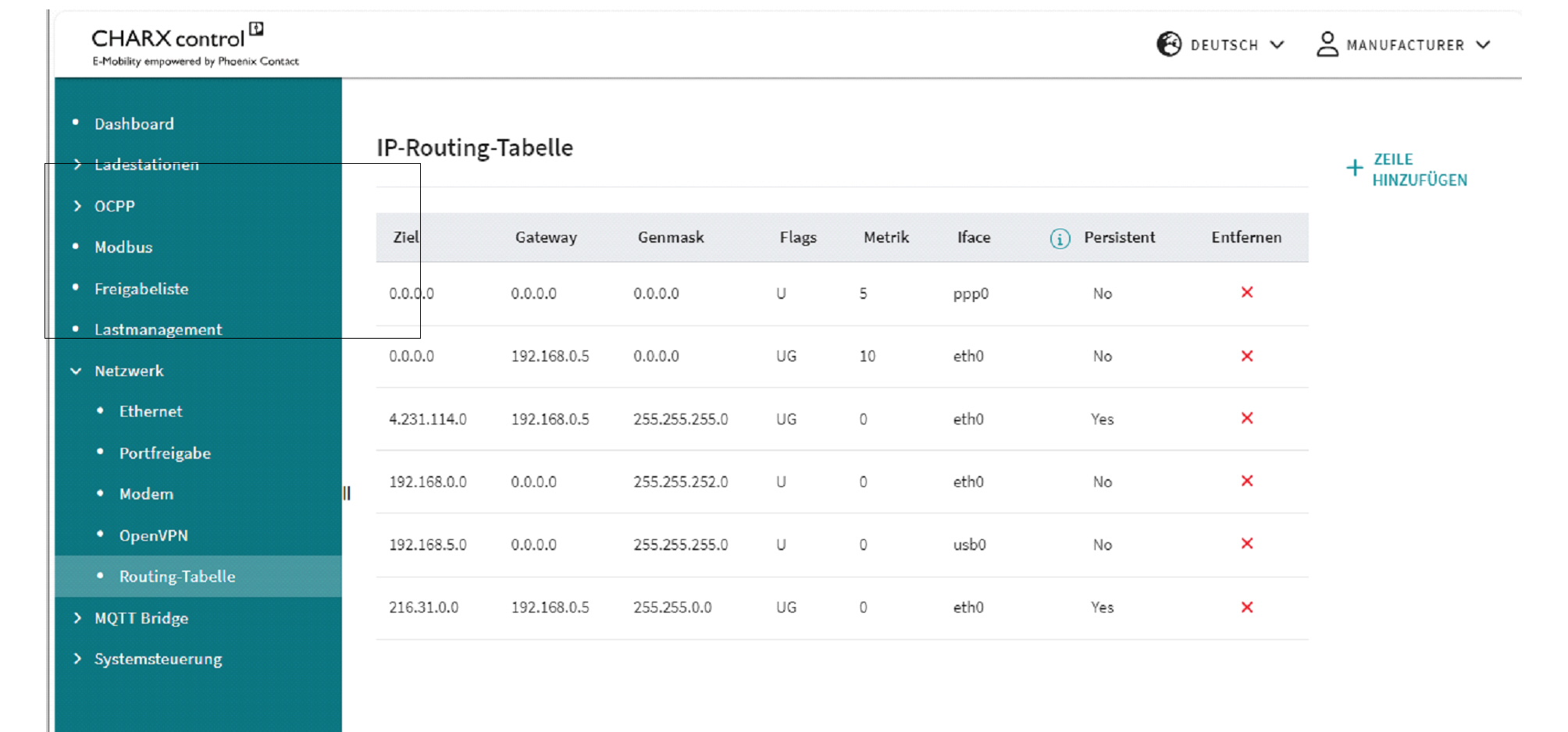 Routing Table
|
Routing Table |
|
|---|---|
|
Destination |
IP address in the destination network |
|
Gateway |
Gateway via which the destination network is to be reached |
|
Genmask |
Subnet mask for the destination network |
|
Flags |
U: Up route is valid G: Gateway – the route leads to a gateway router and not to a directly connected network or host H: Host name – the route leads to a host and not to a network, where the destination address is a complete address R: Reject – is set by ARP when an entry expires (e.g., because the IP address could not be resolved into a MAC address) D: Dynamic – route added by a route redirection or RIP (if “routed” is activated) M: Modified – route changed by a route redirection C: Cloning – a new route is cloned by this entry when it is used L: Link – information at connection level, e.g., the Ethernet MAC address, is available S: Static route added with the route command |
|
Metric |
Specifies the preference for a route (smaller metric = higher preference) |
|
Iface |
Physical interface via which the gateway is to be addressed: eth0: Ethernet interface THH0 ppp0: Cellular interface usb0: USB interface |
|
Persistent |
Route is permanently stored |
|
Remove |
Button for removing an IP route |
|
Add Row |
Button to open an input mask for creating a new route |
Adding a routing rule
Figure 5-29Adding routing rules
|
IP Routing Table - Add Rule |
|
|---|---|
|
Network |
Input field for the IP destination address for which the route is to be used in IPv4/subnet mask format (e.g., subnet mask “/32” = 255.255.255, “/24” = 255.255.255.0) In order to also be able to route IPv4 destination addresses that are not static, it can make sense to mask the rear area of the destination address. Pay attention to any conflicts with other destination addresses and create additional routing rules for this, if necessary. |
|
Gateway |
Input field for the gateway via which the destination network is to be reached |
|
Interface |
Selection field for available network interfaces |
|
Metric |
Input field for the preference for the route, 0 = highest preference |
|
Persist |
Selection field to determine whether a routing rule is retained after the restart |
|
APPLY |
Created routing rule is accepted and applied |
|
CANCEL |
Created routing rule is not accepted |
Removing a routing rule
IP routes can be deleted via the “Remove” icon. The deletion of persistent routes is confirmed via the pop-up window.
Figure 5-30Removing routing rules (persistent)
When removing the non-persistent routes – usually created by the system – it is possible to specify whether they are to be deleted persistently or whether they should be available again after a restart. Deleted routing rules remain visible so they can be reactivated if required.
Figure 5-31Removing routing rules (non-persistent)
MQTT Bridge
In the “MQTT Bridge” area, the connection to a remote MQTT broker can be configured and topics of the local MQTT broker to be forwarded to the remote MQTT broker can be selected.
5.10.1MQTT Bridge/Configuration
Figure 5-32Configuration of the connection to the remote MQTT broker
|
MQTT Bridge/Configuration |
|
|---|---|
|
Configuration |
|
|
Broker |
Displays the connection status to the OpenVPN server: “connected”/“not connected” |
|
Broker Port |
Displays the IP address of the OpenVPN server from the OpenVPN configuration file (only displayed if the IP address is stored in the configuration file, no DNS resolution is performed) |
|
User |
Displays the IP address assigned to the charging controller in the OpenVPN network by the VPN server |
|
Password |
Displays the duration of the current connection to the OpenVPN server |
|
Added Prefix |
Prefix that is automatically added to the selected local MQTT topic, e.g., to assign this to a charging station type |
|
Station Name |
Text fields for clear identification of the charging station at the remote MQTT broker. On the remote MQTT broker side, these can be read via the topic <Prefix>/<Device type>/<Device ID>/config, e.g., Topic: CHARX/ev3000/d5ae6274053159d4/config {“device-type”: “ev3000”, “id”: “d5ae6274053159d4”, “name”: “Test station”, “location”: “Blomberg”} |
|
Location |
|
|
Certificate |
Displays the upload of the current certificate |
|
Button |
|
|
UPLOAD |
Button for opening a dialog for uploading a current certificate to the controller |
|
SAVE |
Saves the current configuration |
|
CLEAR CONFIGURATION |
Deletes the current configuration. |
Server-side authentication of a certificate must be deactivated. An uploaded certificate to the controller verifies the authenticity of the MQTT broker.
MQTT Bridge/MQTT Topic Forwarding
Figure 5-33MQTT topic forwarding via the MQTT bridge
|
Topic Forwarding |
|
|---|---|
|
MQTT Topic Forwarding |
|
|
Local Topic |
Input field for the local MQTT topic that is to be published over the MQTT bridge to the remote MQTT broker. For a detailed description of the available local MQTT topics, refer to the documentation (see https://www.phoenixcontact.com/en-us/products/ac-charging-controller-charx-sec-3150-1138965). If selected MQTT topics are to be published by all charging points connected to the local MQTT broker, the <Device ID> can be replaced by the wildcard “+”. |
|
Remote Topic |
Input field in which a designation for the MQTT topic can be entered to which a subscription can be created in the remote MQTT broker or that can be published by the MQTT bridge to the local MQTT broker. Note: The following topics are available from the MQTT bridge in order to be published on the local MQTT broker as well as the remote MQTT broker: config: Payload {<Device type>, <Device ID>, <Name>, <Location>} VPN_Connection_State: Payload {<vpn_status>, <vpn_ip>} |
|
Forwarding direction (arrow) |
Selects whether a topic should be published by the remote MQTT broker to the local MQTT broker or vice versa. |
|
Information button |
Opens a pop-up window that displays the topic under which the forwarded topic is published. The charging controller automatically adds the hierarchy <Prefix>, <Device type>, <Device ID> to the topic. You can copy the entire topic to the clipboard and use it for configuring the remote MQTT broker (“Information pop-up for forwarding topics from the MQTT bridge to the local MQTT broker” on page 127). |
|
Button |
|
|
SAVE |
Saves the current topic forwarding configuration |
|
ADD ROW |
Adds another row in which MQTT topics for forwarding can be entered |
Figure 5-34Information pop-up for forwarding topics from the MQTT bridge to the local MQTT broker
Figure 5-35Information pop-up for forwarding topics from the MQTT bridge to the remote MQTT broker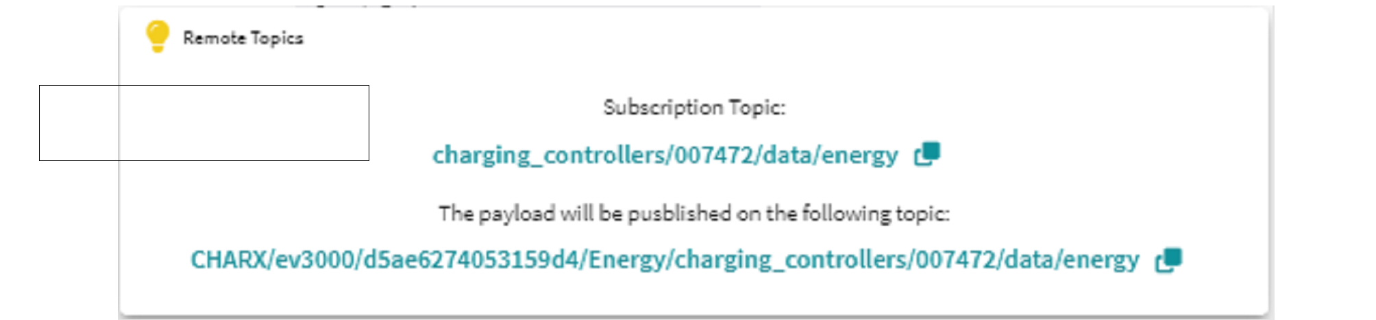
WBM – System Control
System Control/Status
Information regarding the embedded Linux system and the software services (applications) that run on it is provided via the System Control/Status area.
Figure 5-36System Control in the WBM
You can see the currently installed version and the status via the application overview. If necessary, you can restart individual programs via the overview. You can restart the entire system via the “REBOOT SYSTEM” button. Please note that a system restart will terminate active charging processes. It will then be necessary to log into the system again.
|
System Control | Status |
|
|---|---|
|
Application |
|
|
System Monitor |
Provides current system data such as network status or memory capacity and modem data. |
|
Controller Agent |
Standardizes the interface between local charging controllers connected via backplane bus and the clients connected via Ethernet as well as the extension modules connected to them. |
|
OCPP 1.6J |
OCPP 1.6J backend communication |
|
Modbus Client |
Connection of the Modbus/TCP meters connected via Ethernet. |
|
Modbus Server |
Provision of the Modbus/TCP interface for reading charging data and controlling charging processes. |
|
JupiCore |
Collection of data from all connected charging points and its forwarding to the MQTT broker, internal services, and external services via REST API. |
|
Load Management |
Local load and charging management |
|
Web Server |
Web-based management of the charging controller |
|
Calibration Law Agent |
Ensures that the charging station is operated in compliance with calibration laws. |
System Control/Time
You can view and set the current system time and date via the “System Control/Time” area.
Figure 5-37Setting the time in the WBM
It is possible to apply the time set on the PC from the web browser.
UTC time used internally in the system
The charging controller operates internally with the UTC time and uses this for time stamps in the log files and in OCPP communication.
Conversion of OCPP time stamps to the system time
Time stamps from an OCPP backend are converted to the charging controller system time. In order to do this, the UTC time must be sent.
Import/Export
In the “Import/Export” area, you can export or import the current settings for the following sub-registers:
–Charging park
–CHARX RFID/NFC configuration
–Whitelist
–Load management
–OCPP
–System configuration (Ethernet, port sharing, modem)
–MQTT bridge (configuration, topic forwarding)
–OpenVPN
System Control/Calibration Law
In the “System Control/Calibration Law” area, you can make settings for the calibration law. You will also see an overview of the settings relevant to calibration law for the individual charging points and OCPP.
Figure 5-38Status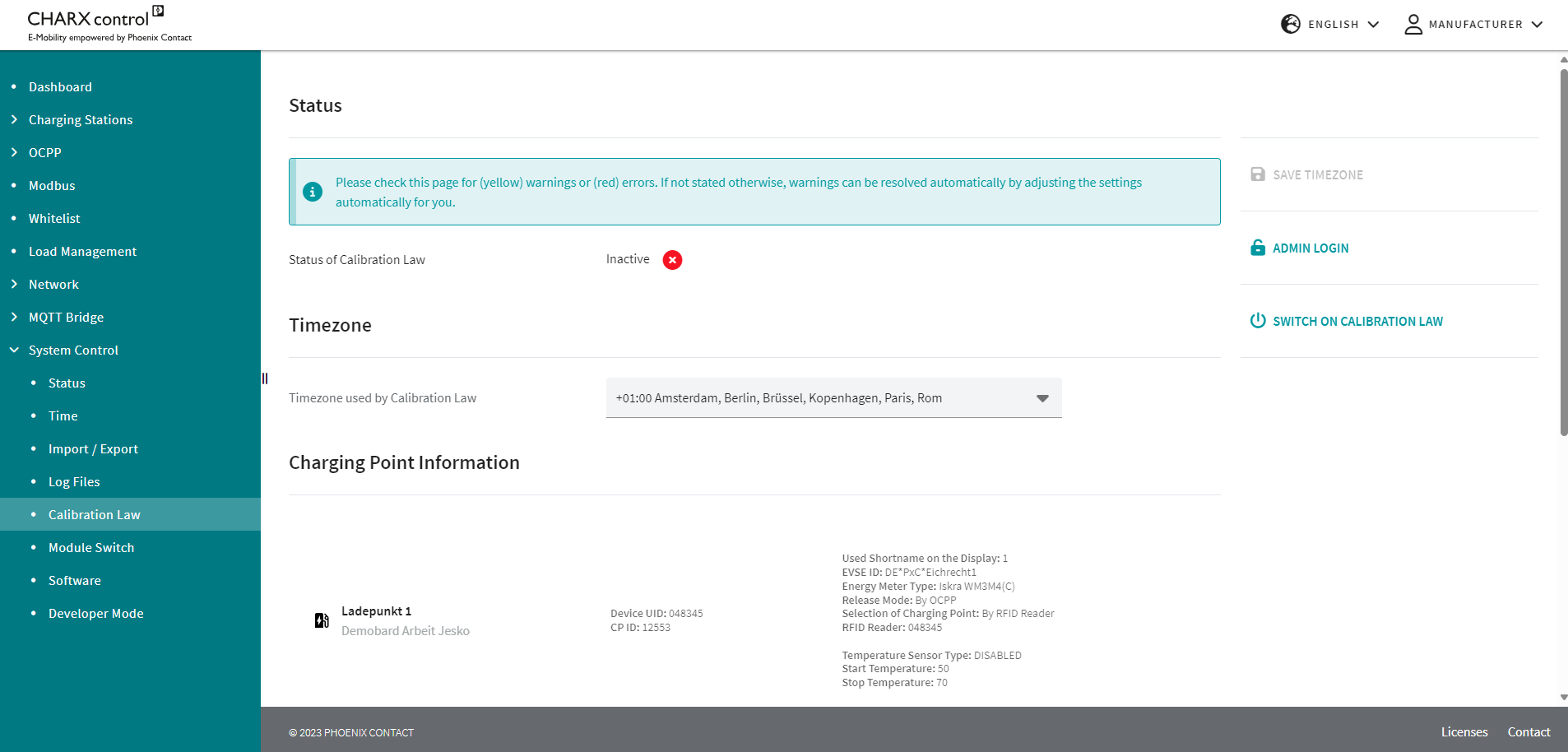
Settings that are not compliant with calibration laws are displayed in red. Warnings are displayed in yellow.
You can activate calibration law using the “SWITCH ON CALIBRATION LAW” button. The controller is then restarted and an additional software service is started.
Further calibration law information
System Control/Developer Mode
In the “System Control/Developer Mode” area, you have access to advanced system functions.
Developer Mode
NOTE: Incorrect settings can result in impairment or failure of the system!
You can change the password for the user “user-app” in the “Linux User Change Password” area. The currently valid password is required for this.
The changed password remains in place after a complete system update and is not reset.
You can reset the password for the user “user-app” to the delivery state (password: user) by clicking on the “RESET PASSWORD” button.
System Control/Log Files
In the “System Control/Log Files” area, you can download the current log data for the system and the application software by pressing the “DOWNLOAD LOGS” button.
The log data for the relevant software services is saved in various files. When the log files are downloaded, they are compressed into one file. The log files can be extracted on the target computer.
Figure 5-39Downloading log files in the WBM
Phoenix Contact Support
If problems occur when operating the charging controller, you can contact Phoenix Contact Support (automation-service@phoenixcontact.de).
Have the following information ready:
–Log files
–Error description
–Details of the charging controllers used
Accessing the log files via OCPP
The log files can also be accessed by the charging controller via the OCPP command “GetDiagnostics”.
System Control/Module Switch
In the “System Control/Module Switch” area, you can prepare charging controllers for operation as a client in client/server mode (see “CHARX SEC-3xxx charging controllers in the Ethernet network” on page 19).
By preparing for this switch-over, the automated processes involved when combining charging controllers to create a client/server group can be performed faster.
Some software services are shut down when the button is activated. The system will be restarted. This process can take a few minutes.
Reduced scope of functions in the WBM after module switch-over
Switching to client operating mode deactivates some important functions of the charging controller, which are taken over by the server. This means that only a reduced scope of functions is available in the WBM after switch-over.
WBM only accessible via USB after module switch-over
Following configuration, the WBM can only be accessed via the USB interface under IP address 192.168.5.1.
Figure 5-40Module switch-over for client/server mode
System Control/Software
You can update individual application programs, the charging controller firmware, or the entire system via the “System Control/Software” area.
Figure 5-41Software update via the WBM
Pressing the “INSTALL UPDATE” button opens a file selection dialog where you can select the corresponding software package.
Following successful update, the charging controller must be restarted manually.
If there are additional charging controllers in the network, the updates will be automatically transferred to the relevant connected charging controllers.
Waiting time until software is transferred to connected charging controllers in the network
After the software update on the server and its restart, the server checks the software version on the connected clients and updates the clients in an additional step. The software update is installed on the clients after a restart. Depending on the application and operation, the entire update process can take up to 10 minutes per charging point.