5.4.5Charging Stations/Charge Point/Event Actions
In the “Charging Stations | Charge Point | Event Actions” menu item, specific actions can be assigned to events that occur. The combination of an event and action is referred to as an Event Action. The current state of the inputs and outputs of the controller is shown in the top area of the web page in Figure 5-13.
Figure 5-13View of the Event Actions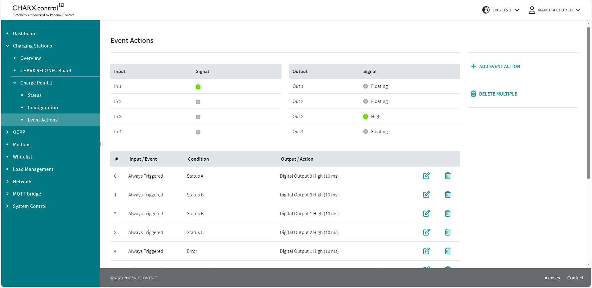
The Event Actions can be triggered internally in the charging controller or also by changes to the input signals. For example, an internal signal could be the rejection of an RFID or the detection of a vehicle that is plugged in. An input signal could be the change of a voltage level at the input or a rising/falling edge. The configured Event Actions are listed below the status of the inputs and outputs. In Figure 5-12, there are three configured Event Actions for controlling the digital outputs.
Each Event Action is associated with an event, which represents the time of the request in the system. Assign an action resulting from the event. You can also request a condition. This is ANDed to the required event. Here, you can add further Event Actions or delete existing Event Actions. The maximum number of configured Event Actions is 32.
Repeated processing of Event Actions
The Event Actions are processed in an endless loop in the specified sequence. This can lead to actions from an Event Action being directly overwritten by a subsequent action and thus not being effective.
Targeted resetting of actions necessary
Depending on the configuration, it may be necessary to cancel actions resulting from Event Actions in a targeted manner when the condition no longer applies. If a condition is not met or a configured event does not occur, this does not automatically mean that the configured action is inverted.
Creating a new Event Action or editing an existing one
Pressing the buttons to create or edit Event Actions opens the Editor. You can select events, actions, and conditions from drop-down fields and make additional settings for them. Figure 5-14 shows the configuration view.
Figure 5-14Configuration view for Event Actions (Event)
Different options can be selected in each column. First, select an input or event that should cause the Event Action in question.
Input or event
The Event Action is only triggered in the case of an event and is ignored for the rest of the time. An event represents a one-time request. If an event is no longer present, the action is not reset.
Charging Park | Charging Stations | Charge Point Details | Event Actions | |
|---|---|
Never Triggered | The event is never triggered, the Event Action is never used. |
Always Triggered | The condition is always queried. An action can be triggered at any time. If a condition changes, this is immediately registered and the Action Timer starts running from the moment of this change. |
New Error | An error is detected. |
Error Resolved | An error no longer occurs. |
Digital Input X Rising | The selected digital input has detected a rising edge. |
Digital Input X Falling | The selected digital input has detected a falling edge. |
Plug Connected | A charging connector has been plugged into the connected charging socket. |
Plug Disconnected | A charging connector has been removed from the connected charging socket. |
EV Connected | A vehicle has been connected to the charging point. |
EV Disconnected | A vehicle has been disconnected from the charging point. |
RFID Charge Release | A charging process has been enabled via an RFID card. |
RFID Denied | An RFID card has been rejected. |
Temperature Derating Started | Curtailment started by the charging controller due to excessively high temperature. |
Temperature Derating Ended | Curtailment has been lifted. |
Contactor Failure Detected | A contactor error has been detected. |
Teach-in Successful | An RFID card has been successfully read and stored in the system. |
Teach-out Successful | An RFID card has been successfully read and removed from the system. |
Teach-in Failed | An RFID card has not been read successfully. |
Condition
Another configuration option is available in the form of conditions that specify the function of Event Actions. Some conditions require further additional settings, which appear below the selection.
Figure 5-15Configuration view for Event Actions (Condition)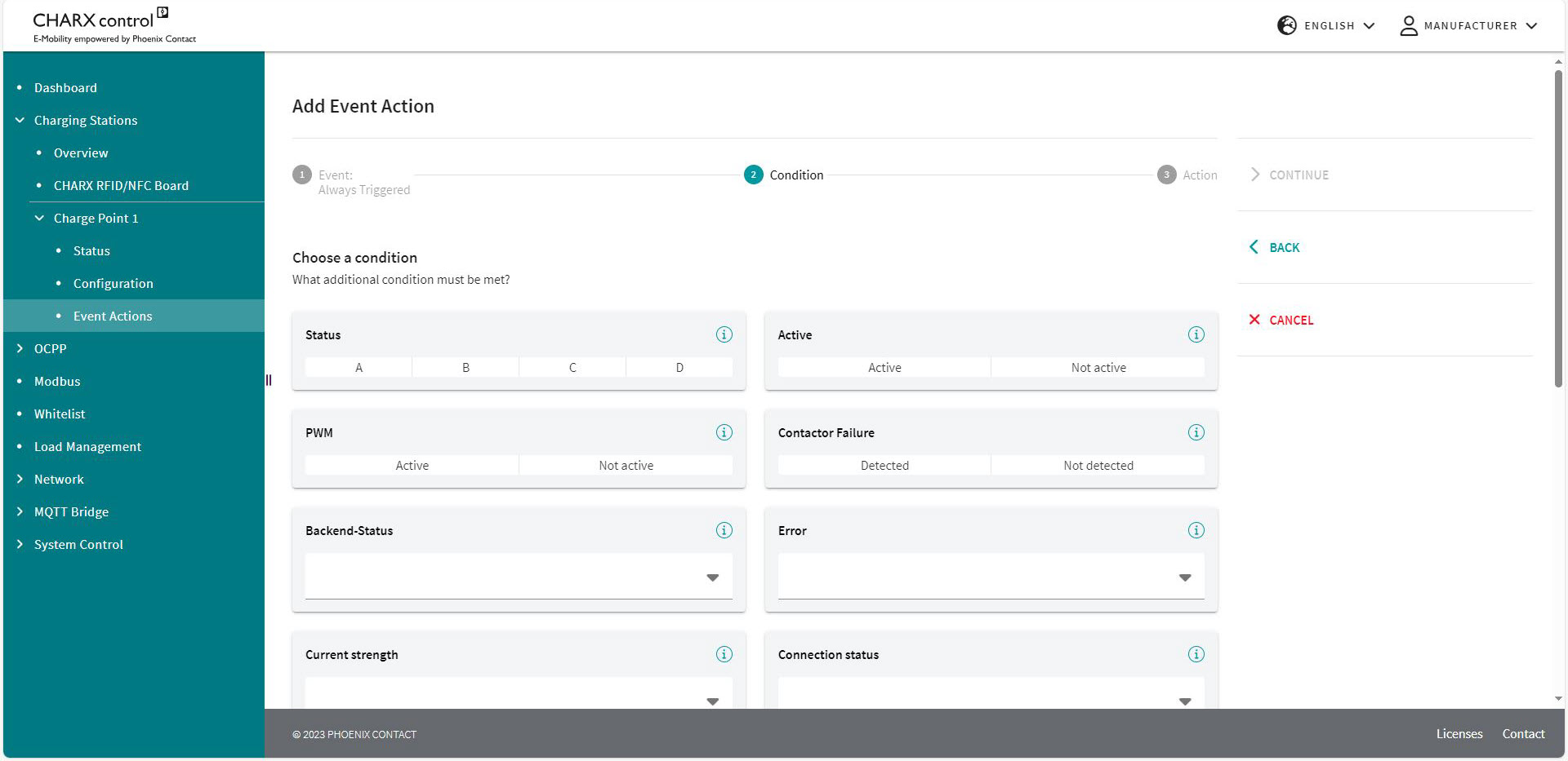
Charging Stations | Charge Point | Event Actions | ||
|---|---|---|
Condition | ||
Never True | The condition is never met, the action cannot be triggered. | |
Active | The condition is always met, the action just depends on the event. | |
Digital Input High | Selection of the input | The selected input corresponds to the High state. |
Digital Input Low | Selection of the input | The selected input corresponds to the Low state. |
Connector plugged | A charging connector is inserted into the charging socket. | |
Error | An error is available in the charging controller. | |
Error Internal | An internal error has occurred in the charging station. | |
Error External | An external error has occurred on the vehicle. | |
PP XX A | The resistance value of the plugged-in charging cable corresponds to the carrying capacity of XX amps. | |
Status A | The charging point is in status A. | |
Status B | The charging point is in status B. | |
Status C | The charging point is in status C. | |
Status D | The charging point is in status D. | |
EV Connected | A vehicle is connected. | |
EV not Connected | There is no vehicle connected. | |
Available | The charging point is in “Available” status. | |
Preparation | The charging point is in “Preparing” status. | |
Charging | The charging point is in “Charging” status. | |
Suspended EV | The charging point is in “Suspended EV” status. | |
Suspended EVSE | The charging point is in “Suspended EVSE” status. | |
Finishing | The charging point is in “Finishing” status. | |
Reserved | The charging point is in “Reserved” status. | |
Unavailable | The charging point is in “Unavailable” status. | |
Contactor Failure Detected | A contactor error has been detected. | |
Last RFID Invalid | The last read RFID is not valid. | |
PP Under Value | PP current in amps | The resistance value of the charging cable is below a specific current value. |
PP Over Value | PP current in amps | The resistance value of the charging cable is above a specific current value. |
Analog Input X Over Value | Analog input voltage | The voltage at the selected input X is above the entered value. |
Analog Input X Under Value | Analog input voltage | The voltage at the selected input X is below the entered value. |
Charge Release | The charging release is present. | |
No Charge Release | The charging release is not present. | |
External Release | The charging point is available. | |
No External Release | The charging point is not available. | |
Temperature Derating | The charging point is curtailed due to excessively high temperature. | |
No Temperature Derating | The charging point is not curtailed. | |
Authorization Request ongoing | Authorization of the RFID card is being requested. | |
No Contactor Failure Detected | The charging contactor is working properly, a contactor error has not been detected. | |
Current reduced for External Reasons | The charging current is reduced by an external specification. | |
Current not reduced for External Reasons | The charging current is not reduced by an external specification. | |
CP PWM on | The charging point communicates with the vehicle via the PWM signal. The PWM signal is active. | |
CP PWM off | The charging point does not communicate with the vehicle via the PWM signal. The PWM signal is not active. | |
Backend offline | No connection to the backend available | |
Backend offline, but charging point available | No connection to the backend, but charging station available | |
Backend online | Connection to the backend available | |
Backend online and charging point available | Connection to the backend and charging station available | |
You can save the edited Event Actions below the settings or cancel editing.
Output or action
You then select an action for the event. This action can be performed continuously or for a specific time. Continuously means until the action is revoked by another Event Action. To define the time you use an Action Timer, which requires a value to be entered in milliseconds. In this way you can, for example, switch on LEDs for a specific time after the triggering.
Some actions require further additional settings, which appear below the Action Timer if this is the case.
Figure 5-16Configuration view for Event Actions (Action)
Charging Stations | Charge Point | Event Actions | ||
|---|---|---|
No Action | There is no action linked to the event. | |
Enable Charging | Enable Status | The charging release is switched. Bus controlled: The charging release is issued and withdrawn via Modbus. Enable: The charging release is set. Disable: The charging release is withdrawn. |
Lock Connector | The actuator moves to the locking position in the charging socket. | |
Unlock Connector | The actuator moves to the unlocking position in the charging socket. | |
Digital Output X Low | The digital output goes to 0 V. | |
Digital Output X High | The digital output goes to 12 V. | |
Digital Output X Floating | The digital output has no potential. | |
Digital Output X Flashing High | Flashing PWM | The digital output flashes and assumes 12 V for a specific period. The entry in Flashing PWM affects the setting of the percentage value for how long the output is set to High in relation to the total period length. Period length = 2 s. |
Digital Output X Flashing Low | Flashing PWM | The digital output flashes and assumes 0 V for a specific period. The entry in Flashing PWM affects the setting of the percentage value for how long the output is set to Low in relation to the total period length. Period length = 2 s. |
Digital Output X Pulsatile Low | The output pulsates and assumes the voltage level of 0 V, increasing and decreasing in time. | |
Digital Output X Buscontrolled | The output can be controlled via internal or external software. | |
Reduce maximum charging current | Reduction maximum current | The set current at the charging point is reduced. The set current should be reduced to this set value in amps. |
External Release | Enable Status | The availability of the charging point is switched. Bus controlled: The availability is set via the Modbus registers. Enable: The charging point is set to available. Disable: The charging point is set to not available. Optionally, a freely definable error description can be sent to an OCPP backend. The event “Digital Input X Rising/Falling” and the condition “Always True” are required for this. If “EmergencyStop” is entered as an error description, the StopReason “EmergencyStop” is transmitted to the backend. |

Action Timer
If an action should cease immediately when a condition changes, set the Action Timer to a very low value (e.g., 10 ms).
If an action should not cease automatically when a condition changes, set the Action Timer to 0 ms.
The action remains until it is manually reset (e.g., by another Event Action). If the one-time occurrence of a short event is to be followed by a longer action, set the Action Timer to the duration of this action.
For example: The RFID card is rejected via OCPP. Then a flashing red LED appears for five seconds.
Examples of Event Action configuration
Event Actions for external specifications
Input | 1 | 2 | 3 |
|---|---|---|---|
Description | Charging release via a digital input as a button when a car is connected. | Shutdown of the charging point by an input. | Current reduction to 16 A by an input. |
Event | Digital Input 1 Rising | Always Triggered | Always Triggered |
Action | Create Charging Release | External Release | Reduce maximum charging current |
Action Timer | 0 ms | 1000 ms | 10 ms |
Reduce maximum Current: 16 A | |||
Condition | Status B | Digital Input High: “Low” | Digital Input High: “High” |
Event Action configuration for the LED charging socket
Connection to the first digital output: Red
Status | Charging point error | Vehicle error | Invalid RFID | Reserved charging point | Vehicle rejected |
|---|---|---|---|---|---|
Description | In the event of a charging point error, the red LED is steady on. | In the event of a vehicle error, the red LED flashes. | In the event of a rejected RFID, the LED flashes for 3 seconds. | If the charging point is reserved, the LEDs light up yellow. | If there is no charging release for the charging point, the LEDs flash yellow. |
Event | Always Triggered | Always Triggered | RFID Denied | Always Triggered | Always Triggered |
Action | Digital Output 1 High | Digital Output 1 Flashing High | Digital Output 1 Flashing High | Digital Output 1 High | Digital Output 1 Flashing High |
Action Timer | 10 ms | 10 ms | 3000 ms | 10 ms | 10 ms |
Condition | Error External | Error External | Always True | Reserved | Suspended EVSE |
Connection to the second digital output: Green
Status | Available | Reserved charging point | Vehicle rejected |
|---|---|---|---|
Description | If the charging point is available, the green LED lights up. | If the charging point is reserved, the LEDs light up yellow. | If there is no charging release for the charging point, the LEDs flash yellow. |
Event | Always Triggered | Always Triggered | Always Triggered |
Action | Digital Output 2 High | Digital Output 2 High | Digital Output 2 Flashing High |
Action Timer | 10 ms | 10 ms | 10 ms |
Condition | Available | Reserved | Suspended EVSE |
Connection to the third digital output: Blue
Status | Preparation | Charge | Vehicle paused |
|---|---|---|---|
Description | If charging is started, the blue LED is steady on. | When the vehicle is charging, the blue LED flashes. | If the vehicle is fully charged or rejects charging, the blue LED flashes slowly. |
Event | Always Triggered | Always Triggered | Always Triggered |
Action | Digital Output 3 High | Digital Output 3 Flashing High; Flashing PWM 50% | Digital Output 3 Flashing High; Flashing PWM 80% |
Action Timer | 10 ms | 10 ms | 10 ms |
Condition | Preparing | Charging | Suspended EV |
Connection to the fourth digital input
Input | 4 | 4 |
|---|---|---|
Description | Stop charging process when emergency switching off switch is pressed | Continue charging process when emergency switching off switch is reset |
Event | Digital Input 4 Rising | Digital Input 4 Falling |
Action | External Release | External Release |
Action Timer | Permanent | Permanent |
Enable Status | Disable Message to OCPP backend: EmergencyStop | Bus-controlled |
Condition | Always Active | Always Active |
Variable „NOTE“ ist nicht definiertEnsure additional safety relay or contactor
This Event Action configuration is only used to transmit the correct StopReason to the OCPP backend. In the event of an emergency shutdown, you must also ensure that the power supply of the charging socket or the charging cable is interrupted by a contactor or safety relay.