
FP 0,8/ 52-FV-SL 4,85
-
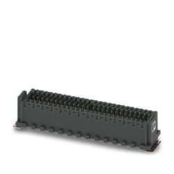
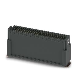
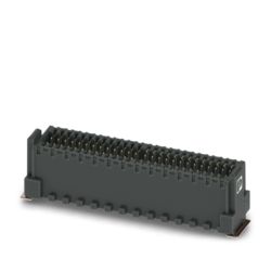
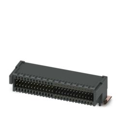
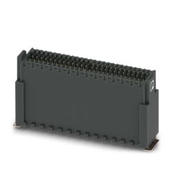
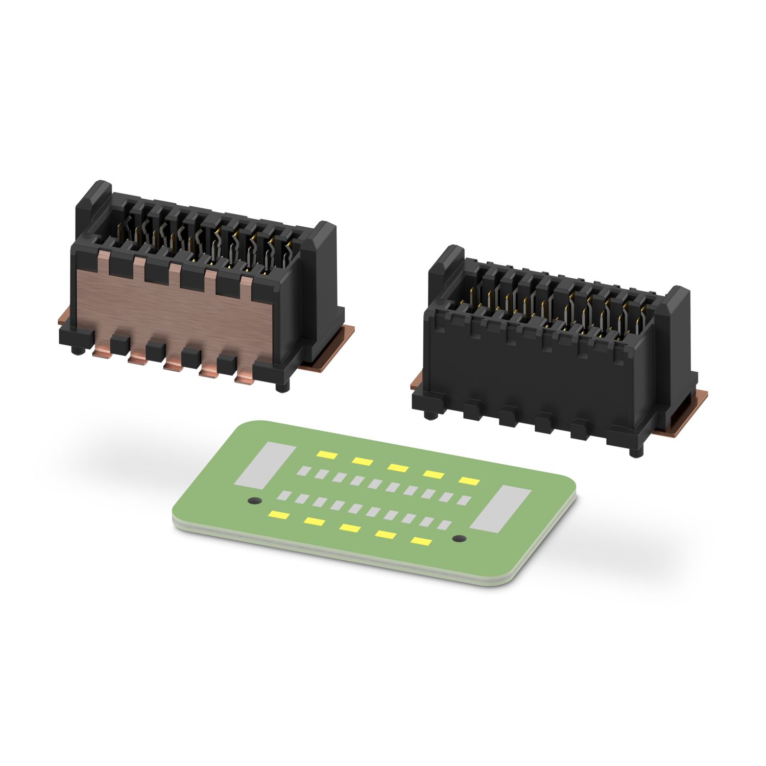
SMD female connectors
1545311
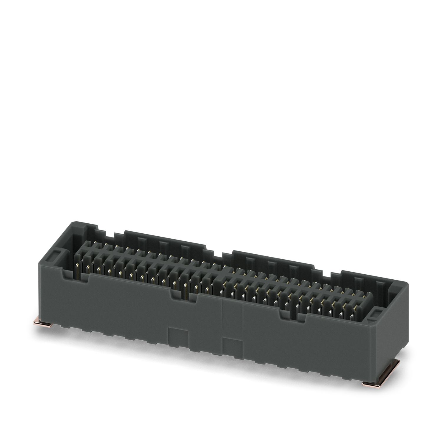
SMD female connector, nominal current: 1.7 A, test voltage: 500 V AC, number of positions: 52, pitch: 0.8 mm, color: black, contact surface: Au, contact connection type: Socket, mounting: SMD soldering
Number of positions
Product details
| Product type | SMD female connector |
| Product family | FP 0,8/...-FV-SL 4,85 |
| Number of positions | 52 |
| Pitch | 0.8 mm |
| Number of rows | 2 |
| Pin layout | Linear pad geometry |
| Properties | |
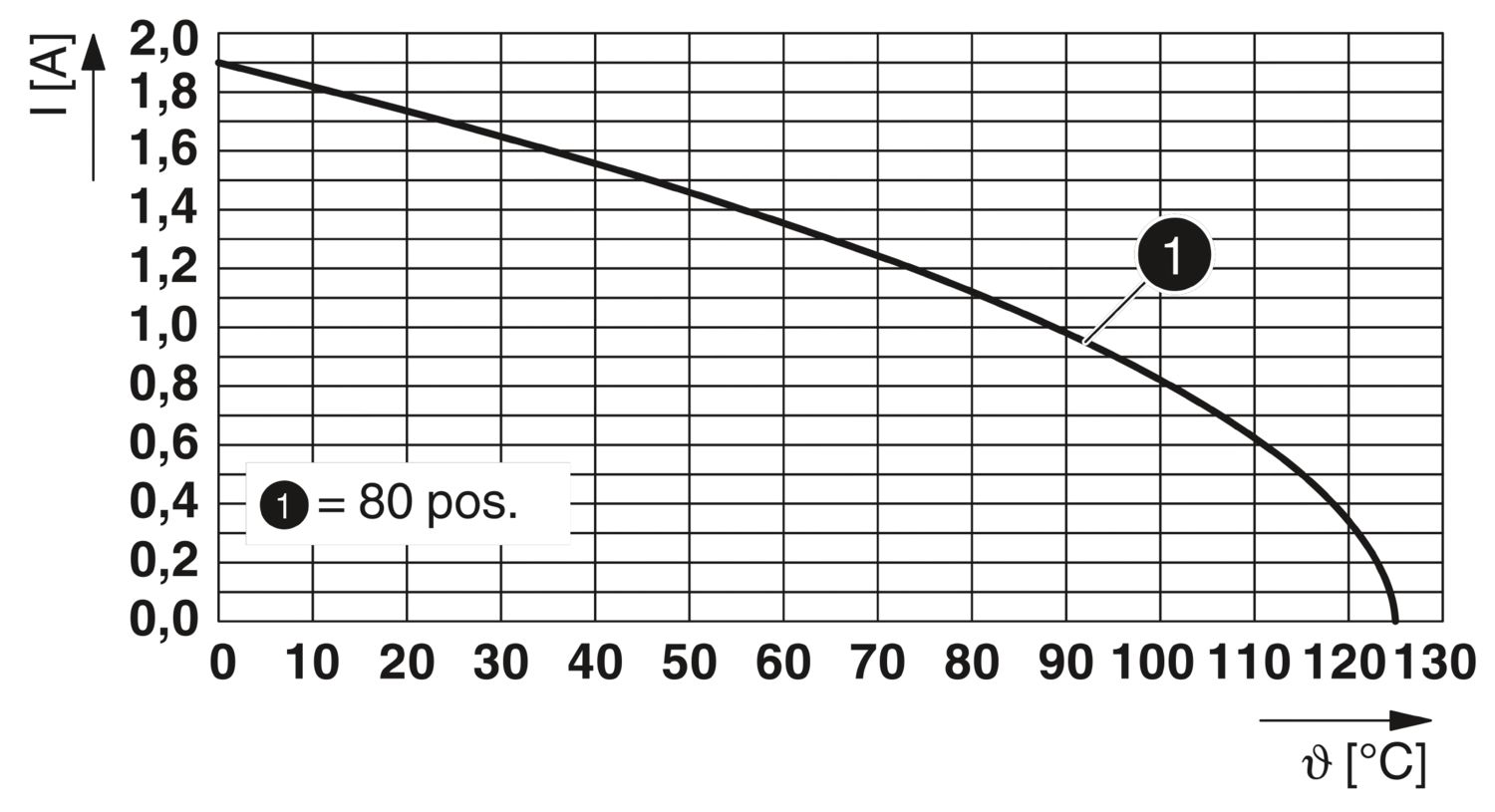
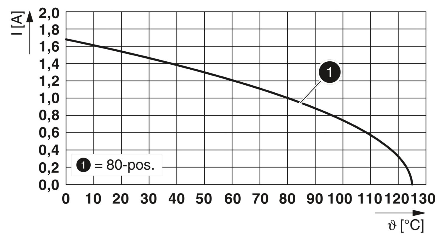
| Nominal current IN | 1.7 A IEC 60512-5-2:2002-02 (at 20°C 80-pos.) |
| Contact resistance | 15 mΩ |
| Test voltage | 500 V AC IEC 60512-4-1:2003-05 |
| Data transmission | |
| Data transmission rate | 16 Gbps |
| Mounting type | SMD soldering |
| Pin layout | Linear pad geometry |
| Processing notes | |
| Process | Reflow soldering |
| Moisture Sensitive Level | MSL 1 |
| Classification temperature Tc | 260 °C |
| Solder cycles in the reflow | 3 |
| Material data - contact | |
| Note | WEEE/RoHS-compliant, free of whiskers according to IEC 60068-2-82/JEDEC JESD 201 |
| Contact material | Cu alloy |
| Surface characteristics | Selective coating |
| Metal surface contact area (top layer) | Gold (Au) |
| Metal surface contact area (middle layer) | Nickel (Ni) |
| Metal surface soldering area (top layer) | Tin (Sn) |
| Metal surface soldering area (middle layer) | Nickel (Ni) |
| Material data - housing | |
| Color (Housing) | black (9005) |
| Insulating material | LCP |
| Insulating material group | IIIb |
| CTI according to IEC 60112 | 150 |
| Flammability rating according to UL 94 | V0 |
| Notes on operation | The permissible voltage during operation depends on the application, taking into consideration the air clearances and creepage distances within the scope of insulation requirements in accordance with IEC 60664-1. |
| Details for soldering processes | The items are suitable for assembly on both sides and for overhead soldering. |
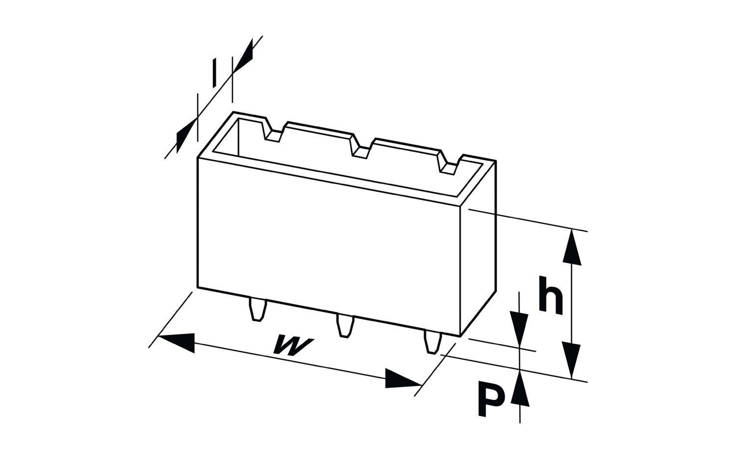
| Dimensional drawing |
|
| Pitch | 0.8 mm |
| Width [w] | 25.58 mm |
| Height [h] | 5.45 mm |
| Length [l] | 6.9 mm |
| Installed height | 4.8 mm |
| Application | |
| Contact cover | 0.8 mm |
| Center offset | ± 0.7 mm in longitudinal and transverse direction |
| Stack height | 6 mm Tolerance: +1,5 mm (in combination with Range of articles:FP 0,8/...-MV-SL 1,15) |
| 7.5 mm Tolerance: +1,5 mm (in combination with Range of articles:FP 0,8/...-MV-SL 2,65) | |
| 12 mm Tolerance: +1,5 mm (in combination with Range of articles:FP 0,8/...-MV-SL 7,15) | |
| 13.5 mm Tolerance: +1,5 mm (in combination with Range of articles:FP 0,8/...-MV-SL 8,65) | |
| Wipe length | 1.5 mm |
| Angular tolerance | ± 5 ° in longitudinal and transverse direction (when plugging in) |
| ± 5 ° in longitudinal and transverse direction (when plugged in) | |
| Axial offset in X direction (longitudinal) | ± 0.3 mm (Tolerance compensation when plugged in) |
| Axial offset in Y direction (transversal) | ± 0.3 mm (Tolerance compensation when plugged in) |
| PCB design | |
| Pad geometry | 0.5 x 1.1 mm |
| Thermal test | Test group C | |
| Specification | IEC 60512-5-2:2002-02 |
| Tested number of positions | 80 |
| Insulation resistance | |
| Specification | IEC 60512-3-1:2002-02 |
| Insulation resistance, neighboring positions | ≥ 5 GΩ |
| Air clearances and creepage distances | | |
| Insulating material group | IIIb |
| Minimum value for clearance and creepage distance | 0.25 mm |
| Vibration test | |
| Specification | IEC 60068-2-6:2007-12 |
| Frequency | 10 - 2000 - 10 Hz |
| Sweep speed | 1 octave/min |
| Amplitude | 1.5 mm (10 Hz ... 60.1 Hz) |
| Acceleration | 200 m/s² (58 Hz ... 2000 Hz) |
| Test duration per axis | 2.5 h |
| Test directions | X-, Y- and Z-axis |
| Durability test | |
| Specification | IEC 60512-9-1:2010-03 (following) |
| Impulse withstand voltage at sea level | 0.8 kV |
| Contact resistance R1 | 15 mΩ |
| Contact resistance R2 | 15 mΩ |
| Insertion/withdrawal cycles | 500 |
| Insulation resistance, neighboring positions | ≥ 5 GΩ |
| Climatic test | |
| Specification | IEC 60512-11-7:2003-05 |
| Corrosive stress | Method 1, 10 days |
| Power-frequency withstand voltage | 500 V AC |
| Shocks | |
| Specification | IEC 60068-2-27:2008-02 |
| Pulse shape | Semi-sinusoidal |
| Acceleration | 490 m/s² |
| Shock duration | 11 ms |
| Test directions | X-, Y- and Z-axis (pos. and neg.) |
| Ambient conditions | |
| Ambient temperature (operation) | -55 °C ... 125 °C |
| Ambient temperature (storage/transport) | -40 °C ... 70 °C |
| Relative humidity (storage/transport) | 30 % ... 70 % |
| Ambient temperature (assembly) | -5 °C ... 100 °C |
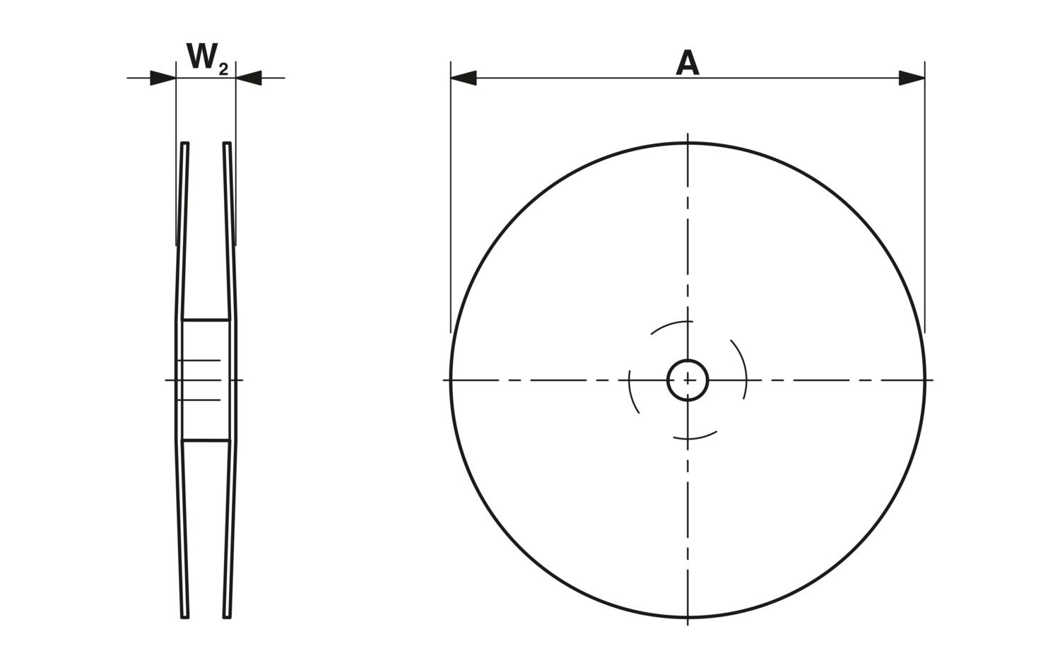
| Dimensional drawing |
|
| Type of packaging | 44 mm wide tape |
| [W] tape width | 44 mm |
| [W2] coil overall dimension | ≤ 50.4 mm |
| [A] coil diameter | ≤ 330 mm |
| Outer packaging type | Transparent-Bag |
Compatible products
Your advantages
Reliable mechanical and electrical connections, thanks to the double-sided ScaleX contact system
Robustness: ScaleX technology for high tolerance compensation and protection of contacts
Flexible device design: various numbers of positions, designs, and stack heights with high wipe lengths
Frequently asked questions
What is ScaleX?
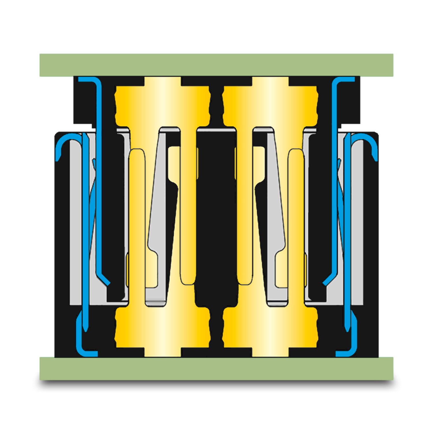
ScaleX is our registered technology trademark for a patented contact system. The unique double contact ensures a reliable, robust connection with two contact points. The contacts are extremely well protected in the housing and offer high tolerance co... View more
ScaleX is our registered technology trademark for a patented contact system. The unique double contact ensures a reliable, robust connection with two contact points. The contacts are extremely well protected in the housing and offer high tolerance compensation during insertion, which promotes the longevity of the connection. Even in the inserted state, outstanding tolerance compensation of ± 0.3 mm is possible and several connectors can be placed on one PCB. This is a particularly valuable feature of ScaleX technology and enables completely new device designs.
View lessWhat makes the FP 0,8 series board-to-board connector so special?
A key feature of the FP 0,8 series is the ability to arrange several board-to-board connectors on one PCB. This enables new flexibility in device design. The basis for this is high tolerance compensation both during inserting and in the inserted stat... View more
A key feature of the FP 0,8 series is the ability to arrange several board-to-board connectors on one PCB. This enables new flexibility in device design. The basis for this is high tolerance compensation both during inserting and in the inserted state. Thanks to ScaleX technology, the FP 0,8 is a versatile specialist in terms of robustness, flexibility, and variability. The system is characterized by high data transmission rates of up to 52 Gbps and a current carrying capacity of 1.7 A per contact (at 20°C). The shielded (SH) and unshielded (SL) versions with the same footprint enable flexible PCB layout design without adaptation when changing versions.
View lessCan I also achieve higher nominal currents than 1.7 A per contact?
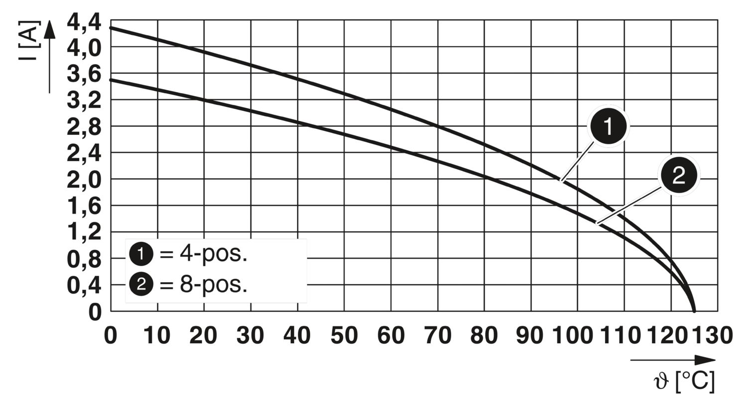
Yes, the nominal current is 1.7 A per contact for a fully energized, 80-pos. connector at an ambient temperature of 20°C. For an 80-pos. version with 1.7 A per contact, for example, this means a total of 80 x 1.7 A = 136 A. The derating curve shows t... View more
Yes, the nominal current is 1.7 A per contact for a fully energized, 80-pos. connector at an ambient temperature of 20°C. For an 80-pos. version with 1.7 A per contact, for example, this means a total of 80 x 1.7 A = 136 A. The derating curve shows the temperature-dependent current carrying capacity for different numbers of positions. In practice, selective pins are often energized, which achieves even higher currents per contact. Example: With selective energization of four contacts, 3.9 A per contact can be achieved, i.e. a total of 4 x 3.9 A = 15.6 A.
The shielded item version is also suitable for current transmission via the two shielding plates on the side of the item, so that 16 A can be transmitted per shielding plate in an 80-pos. version. A derating curve for the shielding plate can also be found in the technical data.
With which numbers of positions is the FP 0,8 board-to-board connector available?
The FP 0,8 product family is available with five different numbers of positions (12, 20, 32, 52, and 80), each as a shielded or unshielded version. Other numbers of positions are available on request.
How can the solder contacts be inspected after reflow soldering?
SH (shielded) and SL (short layout, unshielded) versions: CT scan or X-ray analysis required, as the contacts are located under the component.
AOI (unshielded) versions: AOI-capable, as the contacts are routed out and visible.
Are the different item versions from the FP 0,8 series compatible with regard to the footprint?
The items from the unshielded FP 0,8-SL series are compatible with the footprint of the shielded FP 0,8-SH items. It is therefore possible to switch flexibly between items from the FP 0,8-SH and FP 0,8-SL series without having to adapt the PCB layout... View more
The items from the unshielded FP 0,8-SL series are compatible with the footprint of the shielded FP 0,8-SH items. It is therefore possible to switch flexibly between items from the FP 0,8-SH and FP 0,8-SL series without having to adapt the PCB layout.
View lessWhy are there two unshielded AOI and SL versions in the FP 0,8 series?
The unshielded AOI version offers the advantage of the exposed solder contacts for automatic optical inspection.
The unshielded SL version (shieldless) has the advantage that the solder contacts and therefore the footprint on the PCB are identical...
View more
The unshielded AOI version offers the advantage of the exposed solder contacts for automatic optical inspection.
The unshielded SL version (shieldless) has the advantage that the solder contacts and therefore the footprint on the PCB are identical to the shielded SH version. This means that shielded and unshielded versions can be used without changing the PCB layout. Here, the solder joints can be checked via CT scan or X-ray analysis.
Does the specified data transmission rate apply to all combinations?
No, the specified data transmission rate refers to an example combination. It may vary depending on the item combination. Factors such as different stack heights - due to longer or shorter contacts - influence the signal quality and thus the achievab... View more
No, the specified data transmission rate refers to an example combination. It may vary depending on the item combination. Factors such as different stack heights - due to longer or shorter contacts - influence the signal quality and thus the achievable data rate. We can work with you to optimize high-speed data transmission for individual applications. Feel free to contact us.
View lessWhere can I find information on extended air clearances and creepage distances to realize the necessary voltage requirements in my application?
The minimum distances are specified in the technical data. We are happy to calculate distances for partially assembled connectors or between omitted pins (so-called death metal parts) on request. This means that increased voltage requirements can also be realized.