Alarm
What you will find in this section:
The digital output complies with IEC 61131-2 Type 3. It can be configured via the web server or the Modbus communication interface.
Alarm
If limit value alarms are present (see chapter: Alarming) and the function of the digital output is set to Alarm, the digital output can reflect these alarms.
|
Navigation on the web server |
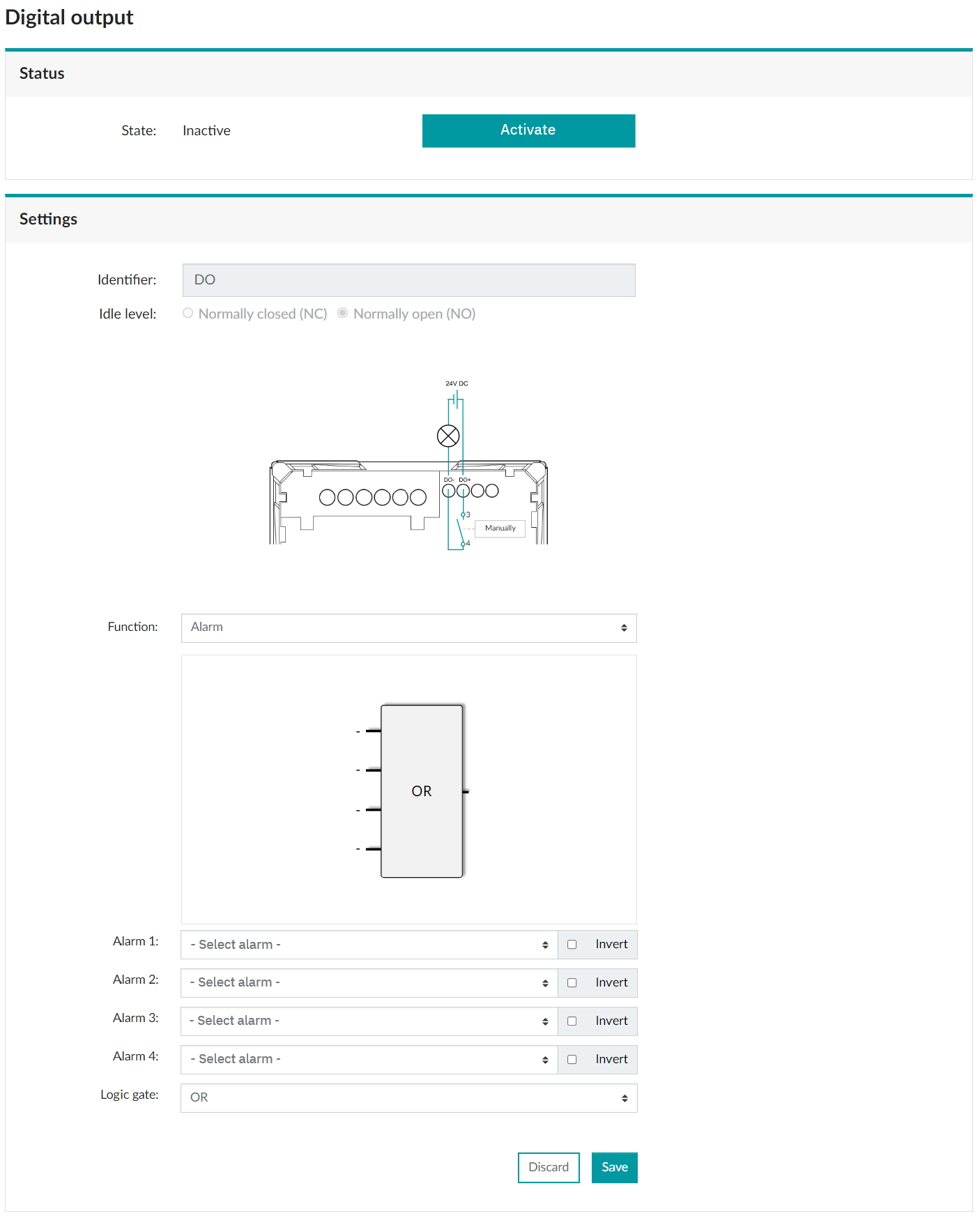
Menu: “Settings, Digital output”, “Alarm” function |
|
Status |
The “Status” area shows the current status of the digital output. |
|
Identifier |
The identifier can be used to assign a user-specific designation to the digital output. |
|
Idle level |
There are two possible statuses for the idle level.
|
|
Function |
Select the “Alarm” function. |
The integrated logic gate makes it possible to define several alarm messages for the alarm function of the digital output. The digital output can be used for this type of multiple assignment, depending on up to four alarms/thresholds.
|
Alarm 1…4: |
Select the alarms that are to be linked to the logic gate. You can use the checkbox to invert the signal. |
|
Logic gate |
An operator has to be defined for the function of the logic gate. |
Select a logic operator from the drop-down menu:
- AND
- OR
- XOR
- NAND
- NOR
- NXOR
The alarms themselves are configured via “Settings, Alarms”.
Function description of the logic gate
The logic gate links configured statuses of the respective alarms with an assigned logic function. Various application-specific statuses can be monitored, depending on how the connections are combined.
Below, you can find explanations on how the logic operators work:
AND operator

When all alarms are active at the same time, this signal output is set.
If one of the alarms is no longer active, this signal output is reset.
NAND operator
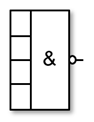
When none of the alarms are active, this signal output is set.
If one of the alarms is active, this signal output is reset.
OR operator

When one of the alarms is active, the signal output is set.
If none of the alarms are active, this signal output is reset.
NOR operator
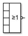
When none of the alarms are active, this signal output is set.
If one of the alarms is active, this signal output is reset.
XOR operator

If an alarm is active, this signal output is set.
If none or several of the alarms are active, this signal output is reset.
NXOR operator
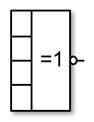
If none or several of the alarms are active, this signal output is set.
If only one of the alarms is active, this signal output is reset.
Related topics