clipx ENGINEER Release Notes 2.5
This document describes the most important changes between versions 2.5 and 2.4.1 of the clipx ENGINEER software from Phoenix Contact (phoenixcontact.com/product/1272241).
The following new features have been added:
- RailFIX – Support for the mechanical mounting of DIN rails
- CAPAROC Station Assistant
- Mechanical machining – Holes extending beyond rail ends
- Mechanical machining – Keyhole cutouts
- Custom zero cut for perforated DIN rails
- Warning labels and warning covers as new accessories
- PLC V8 adapter for relay modules
- Customer-specific item numbers
- Filler plugs and insulating sleeves as new accessories
- Enhanced navigation in the project tree
RailFIX – Support for the mechanical mounting of DIN rails
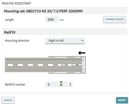
With version 2.5, clipx ENGINEER expands mechanical planning to include support for RailFIX mounting adapters. RailFIX serves as an accessory for the secure mounting of DIN rails on mounting panels.
In clipx ENGINEER, RailFIX is treated as an accessory to the DIN rail and is directly linked to the respective rail. After selecting a DIN rail, the RailFIX wizard can be launched to assist the user with placement. The software automatically calculates the required number of RailFIX adapters based on applicable rules, such as maximum rail length, minimum spacing, and the maximum allowed number per DIN rail. The calculated positions are visualized directly on the rail.
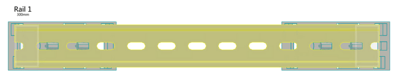
The user can manually adjust the suggested number of RailFIX adapters if necessary. clipx ENGINEER then automatically recalculates the positions. Additionally, the mounting direction of the RailFIX adapters can be changed.
For more information on the RailFIX mounting adapter, visit the Phoenix Contact product page at: https://www.phoenixcontact.com/en-pc/products/mounting-material/railfix.
CAPAROC Station Assistant
With version 2.5, clipx ENGINEER expands its functionality with a CAPAROC Station Assistant, which significantly simplifies the configuration of CAPAROC station systems. The assistant guides users step-by-step through the setup of a station and ensures that only compatible components are selected.
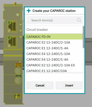
Once a power module is placed, the appropriate base rail is automatically generated, and the configuration process continues directly. clipx ENGINEER automatically handles key tasks, including optimizing sockets and extensions, ensuring that a technically valid and optimized station is created at all times.
Mechanical machining – Holes extending beyond rail ends
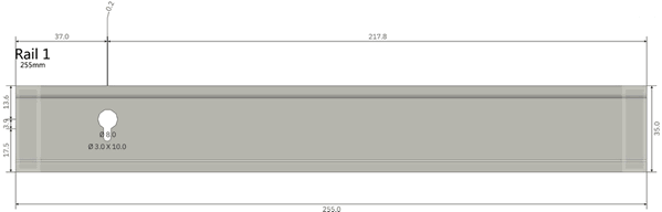
With version 2.5, clipx ENGINEER expands the mechanical machining capabilities for unperforated DIN rails. Starting immediately, drill holes can also be placed beyond the start and end dimensions of the DIN rail. In practice, drill holes are often used at both ends of unperforated DIN rails that extend beyond the actual end of the rail. These holes are created by existing punching tools and are relevant for mounting on the mounting panel. clipx ENGINEER now makes it possible to represent these drill holes realistically.
To do this, the user selects the unpunched DIN rail and activates the mode for mechanical machining. The drill hole can then be placed directly at the beginning or end of the DIN rail so that it extends beyond the rail edge. At the same time, clipx ENGINEER ensures that the placement remains compliant with regulations and prevents drill holes from lying outside the DIN rail.

This enhancement brings mechanical design even closer to actual manufacturing, and typical assembly variations can be modeled directly in the project without workarounds.
Mechanical machining – Keyhole cutouts
With version 2.5, clipx ENGINEER supports the creation of keyhole cutouts on DIN rails. In practice, these are created by combining elongated hole and round hole punching.
clipx ENGINEER now allows round holes to be precisely placed over existing elongated holes, enabling the typical keyhole geometry to be represented realistically. Overlapping machining operations are permitted without additional restrictions.
This enhancement enables a practical representation of manufacturing processes and increases flexibility in the mechanical design of DIN rails.
Custom zero cut for perforated DIN rails
With Version 2.5, clipx ENGINEER expands the mechanical machining of perforated DIN rails by adding the ability to define the zero cut on a project-by-project basis. This allows the zero cut of a DIN rail used in the project to be defined independently of the default settings stored in the project template.
To do this, the user selects the desired perforated DIN rail in the project and activates the mode for mechanical processing. In this mode, clipx ENGINEER provides all relevant functions for perforated DIN rails, including the definition of the DIN rail length and the zero cut. By entering an offset, the zero cut can be specifically adjusted for the selected DIN rail without changing the global settings of the project template.
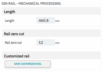
Additionally, it is possible to save the custom-adapted DIN rail and reuse it for future projects. This allows project-specific or customer-specific designs to be efficiently standardized while maintaining maximum flexibility in mechanical planning.
Warning labels and warning covers as new accessories
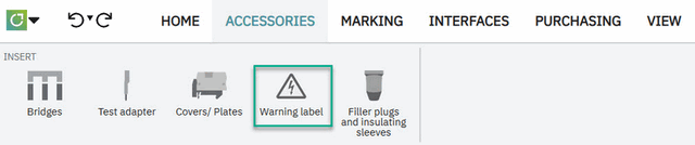
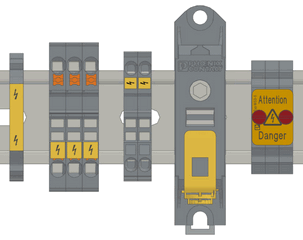
With version 2.5, clipx ENGINEER expands its range of accessories to include warning labels and warning covers for various terminal block families. These accessories serve for clear safety labeling as well as touch protection and can now be planned and placed directly within the project.
Placement is performed via a dedicated mode, which is activated via the accessories ribbon or the circular menu. After selecting the terminal blocks, clipx ENGINEER displays the appropriate warning labels in the insertion center as well as the available insertion points directly at the terminal block. The warning labels can then be inserted with a mouse click or via drag-and-drop.
For power-level terminals and special terminal types, warning covers are also supported; these serve as touch protection and restrict or prevent the connection of conductors depending on the terminal type. Here, too, clipx ENGINEER ensures that only compatible covers are offered and placed in compliance with regulations.
By integrating warning labels and warning covers, clipx ENGINEER supports comprehensive, standards-compliant, and practical safety labeling directly within the engineering process. For more information on the available products, visit the Phoenix Contact product page on plant marking: Plant Marking for Optimal Orientation | Phoenix Contact.
PLC V8 adapter for relay modules
With version 2.5, clipx ENGINEER supports the placement of PLC V8 adapters on PLC relay modules to create valid 8-channel system connections.
For placement, exactly eight relay modules must be selected that are arranged directly next to each other and have the same module width. After activating adapter mode, only the compatible PLC V8 and RIF V8 adapters are automatically displayed in the Insertion Center.
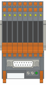
Placement can be performed using insertion points or via drag-and-drop. This ensures that adapters are used exclusively in technically correct configurations and provides optimal support for the user in creating valid system setups.
Customer-specific item numbers
With version 2.5, clipx ENGINEER supports the use and storage of customer-specific item numbers for the first time. This allows users to map their own item number structures in clipx ENGINEER and use them consistently.
The mapping between the original Phoenix Contact item number and the customer-specific item number can be maintained directly in clipx ENGINEER or imported via an Excel list. The Excel lists follow a simple two-column structure in which the original item number is mapped to the customer-specific item number. Multiple mapping lists can be managed in parallel and assigned to individual project templates, allowing for flexible mapping of different customer or project scenarios.
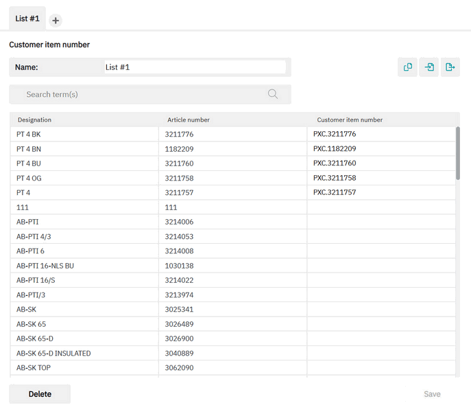
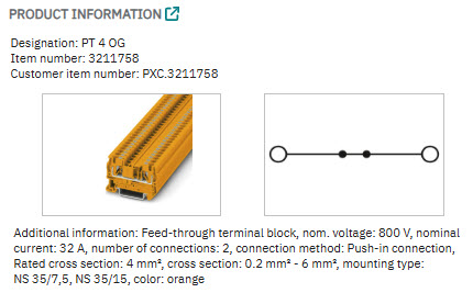
Customer-specific item numbers are then available throughout the engineering process. They can be used for searching in the Insertion Center, displayed in product information, and included in bills of materials within project documentation. This ensures consistency between engineering data, internal item numbers, and customer-specific designations.
Filler plugs and insulating sleeves as new accessories
With version 2.5, clipx ENGINEER expands its accessory functions to include filler plugs and insulating sleeves for terminal blocks. These components enable practical adaptation of wire connections by either completely closing wire openings or reducing their diameter for smaller conductors.
A dedicated accessory mode is available for placement. Once activated, insertion points are displayed on the terminal blocks, and the compatible filler plugs and insulating sleeves are automatically filtered in the accessories area.

The placed accessories are visualized in the 3D model and included in all relevant documentation and bills of materials.
Enhanced navigation in the project tree
With version 2.5, navigation in the project tree has been further improved. By double-clicking on elements in the project tree, they can now be specifically displayed and focused on in the workspace.
This allows users to orient themselves more quickly within complex projects and view relevant project areas directly without having to navigate manually. This feature supports a more efficient workflow and makes it easier to work with extensive project structures.
Fixes
With version 2.5, the following bugs have been fixed:
- The display of markings has been corrected so that black areas no longer appear on marking materials and all content remains clearly legible.
- An error in the order of markings has been fixed, so markings are once again transferred to the marking system in the correct sequence.
- Incorrect collision warnings for PTRV terminal blocks have been corrected, so that only relevant messages are now displayed.
- An upload error ('Cannot access a closed stream') during parallel usage has been fixed, so uploads now work reliably.
- The transfer of device designations (DT / Full DT) from EPLAN has been corrected, so all designations are now imported completely.
- An issue has been fixed where an order was blocked by the current UI state.
- A bug has been fixed where the bridge type changed unexpectedly when shortening bridges.
- Duplicate marking fields after PCP imports are now prevented, ensuring that markings remain unique.
- The display of accessories for D-ST 6-TWIN has been corrected, so all components are shown properly.
- A bug has been fixed where the project name was not transferred correctly after a PCP import.
- The replacement of third-party DIN rails now works reliably.
- ECAD export with PTFIX components now works correctly again.
- Issues during export from production projects have been resolved, so ECAD and marking exports now run reliably.
- The device designation is now displayed correctly in the preview.
- A bug has been fixed where ordering was not possible for virtual rails.
- Problems with item mapping have been corrected, so items can now be found and assigned reliably.
- A bug has been fixed where marking content was lost when widths were changed.
- The width factor for markings is now set correctly, ensuring that content remains visible.
- Missing order buttons in the user interface have been restored.
- An issue has been fixed where bridges (e.g., for PTI terminal blocks) were not transferred from ECAD.
- Saving projects locally now works reliably again after cloud storage.
- Empty marking fields are no longer displayed as black areas, but are shown correctly in a neutral way.