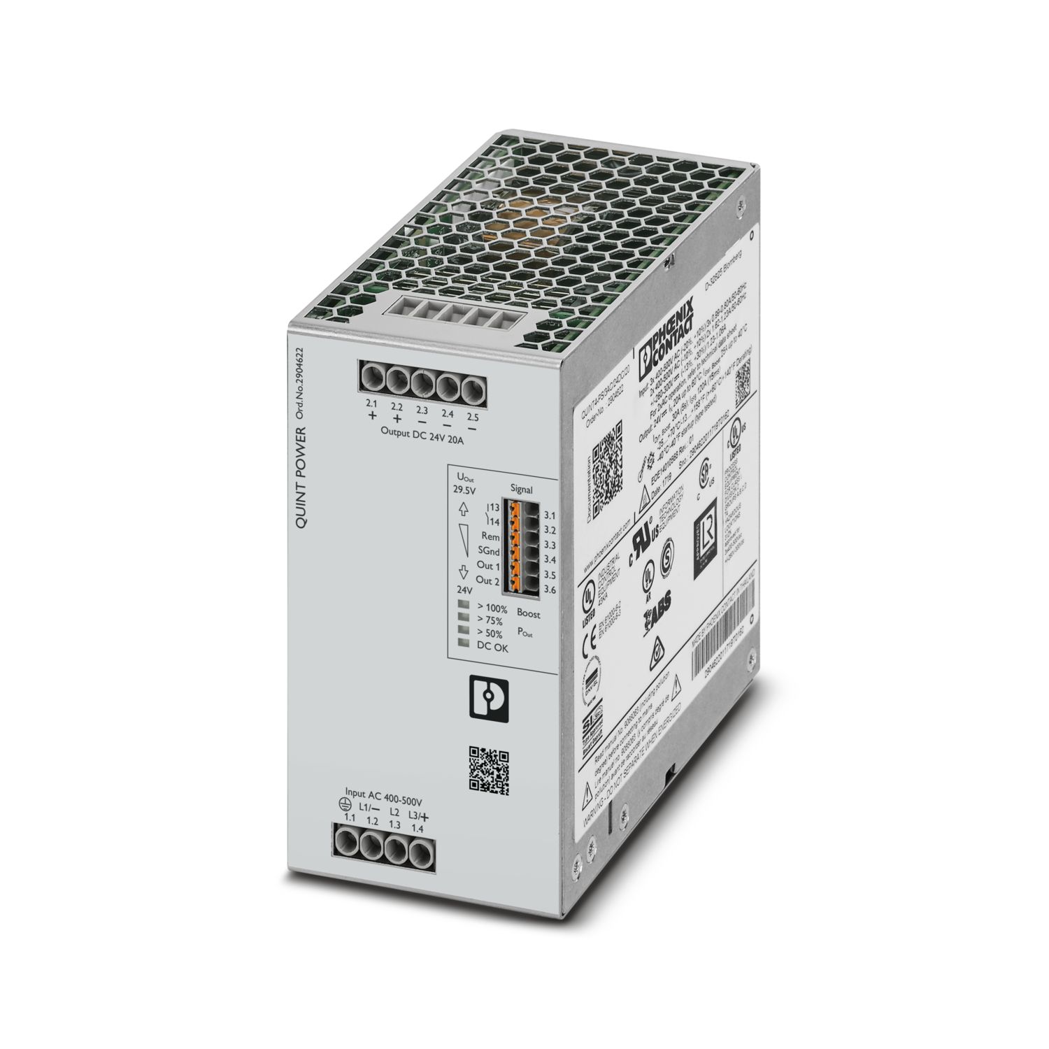
The fourth generation of the high-performance QUINT POWER power supplies ensures superior system availability by means of new functions. Signaling thresholds and characteristic curves can be individually adjusted via the NFC interface.
The unique SFB technology and preventive function monitoring of the QUINT POWER power supply increase the availability of your application.
QUINT4-PS/3AC/24DC/20/KONF1
-
Power supply
1035480
Preconfigured version of the primary-switched QUINT POWER power supply for DIN rail mounting with free choice of output characteristic curve and SFB (Selective Fuse Breaking) Technology, input: 3-phase,
output: 24 V DC / 20 A
Free download available.
Downloads
Product details
| Control input (configurable) Rem | Output power ON/OFF (SLEEP MODE) |
| Default | Output power ON (>40 kΩ/24 V DC/open bridge between Rem and SGnd) |
| AC operation | |
| Network type | Star network |
| Nominal input voltage range | 3x 400 V AC ... 500 V AC |
| 2x 400 V AC ... 500 V AC | |
| Input voltage range | 3x 400 V AC ... 500 V AC -20 % ... +10 % |
| 2x 400 V AC ... 500 V AC -10 % ... +10 % | |
| Typical national grid voltage | 400 V AC |
| 480 V AC | |
| Voltage type of supply voltage | AC/DC |
| Inrush current | typ. 2 A (at 25 °C) |
| Inrush current integral (I2t) | < 0.1 A2s |
| Inrush current limitation | 3 A (after 1 ms) |
| AC frequency range | 50 Hz ... 60 Hz -10 % ... +10 % |
| Frequency range (fN) | 50 Hz ... 60 Hz -10 % ... +10 % |
| Mains buffering time | ≥ 25 ms (3x 400 V AC) |
| ≥ 25 ms (3x 480 V AC) | |
| Current consumption | 3x 0.99 A (400 V AC) |
| 3x 0.81 A (480 V AC) | |
| 2x 1.62 A (400 V AC) | |
| 2x 1.37 A (480 V AC) | |
| 3x 0.8 A (500 V AC) | |
| 2x 1.23 A (500 V AC) | |
| Nominal power consumption | 541 VA |
| Protective circuit | Transient surge protection; Varistor, gas-filled surge arrester |
| Switch-on time | < 1 s |
| Typical response time | 300 ms (from SLEEP MODE) |
| Recommended breaker for input protection | 3x 4 A ... 20 A (Characteristic B, C or comparable) |
| Recommended fuse for input protection | ≥ 300 V AC |
| Discharge current to PE | < 3.5 mA |
| 1.7 mA (550 V AC, 60 Hz) | |
| DC operation | |
| Nominal input voltage range | ± 260 V DC ... 300 V DC |
| Input voltage range | ± 260 V DC ... 300 V DC -13 % ... +30 % |
| Voltage type of supply voltage | AC/DC |
| Current consumption | 1.23 A (± 260 V DC) |
| 1.06 A (±300 V DC) | |
| Recommended breaker for input protection | 1x 6 A (10 x 38 mm, 30 kA L/R = 2 ms) |
| Recommended fuse for input protection | ≥ 1000 V DC |
| Efficiency | typ. 93.9 % (400 V AC) |
| typ. 93.8 % (480 V AC) | |
| Nominal output voltage | 26 V DC |
| Setting range of the output voltage (USet) | 24 V DC ... 29.5 V DC (constant capacity) |
| Nominal output current (IN) | 20 A |
| Static Boost (IStat.Boost) | 25 A |
| Dynamic Boost (IDyn.Boost) | 30 A (5 s) |
| Selective Fuse Breaking (ISFB) | 120 A (15 ms) |
| Magnetic circuit breaker tripping | A1...A16 / B2...B13 / C1...C6 / Z1...Z16 |
| Derating | > 60 °C (2.5 %/K) |
| Feedback voltage resistance | ≤ 35 V DC |
| Protection against overvoltage at the output (OVP) | ≤ 32 V DC |
| Control deviation | < 0.5 % (Static load change 10 % ... 90 %) |
| < 3 % (Dynamic load change 10 % ... 90 %, (10 Hz)) | |
| < 0.25 % (change in input voltage ±10 %) | |
| Residual ripple | < 60 mVPP (with nominal values) |
| Short-circuit-proof | yes |
| No-load proof | yes |
| Output power | 480 W |
| 600 W | |
| 720 W | |
| Apparent power | 686 VA (400 V, UOUT = 24 V, IOUT = stat. Boost) |
| 698 VA (480 V, UOUT = 24 V, IOUT = stat. Boost) | |
| Maximum no-load power dissipation | < 7 W (400 V AC) |
| < 7 W (480 V AC) | |
| Power loss nominal load max. | < 32 W (400 V AC) |
| < 33 W (480 V AC) | |
| Power dissipation SLEEP MODE | < 5 W (400 V AC) |
| < 5 W (480 V AC) | |
| Crest factor | typ. 1.78 (400 V AC) |
| typ. 2.1 (480 V AC) | |
| Rise time | < 80 ms (UOut = 10 % ... 90 %) |
| Connection in parallel | yes, for redundancy and increased capacity |
| Connection in series | yes |
| Signal | |
| Signal ground SGnd | Reference potential for Out1, Out2, and Rem |
| Signal Out 1 (configurable) | |
| Digital | 24 V DC 20 mA |
| Default | 24 V DC 20 mA 24 V DC for UOut > 0.9 x USet |
| Signal Out 2 (configurable) | |
| Default | 24 V DC 20 mA 24 V DC for POut < 0,8 PN and 3 AC OK |
| Signal relay 13/14 (configurable) | |
| Default | closed (Uout > 0.9 USet) |
| Digital | 24 V DC 1 A |
| 30 V AC/DC 0.5 A | |
| Input | |
| Connection method | Screw connection |
| Conductor cross-section, rigid min. | 0.2 mm² |
| Conductor cross-section, rigid max. | 6 mm² |
| Conductor cross-section flexible min. | 0.2 mm² |
| Conductor cross-section flexible max. | 4 mm² |
| Conductor cross-section AWG min. | 30 |
| Conductor cross-section AWG max. | 10 |
| Stripping length | 8 mm |
| Tightening torque, min | 0.5 Nm |
| Tightening torque max | 0.6 Nm |
| Output | |
| Connection method | Screw connection |
| Conductor cross-section, rigid min. | 0.2 mm² |
| Conductor cross-section, rigid max. | 6 mm² |
| Conductor cross-section flexible min. | 0.2 mm² |
| Conductor cross-section flexible max. | 4 mm² |
| Conductor cross-section AWG min. | 30 |
| Conductor cross-section AWG max. | 10 |
| Stripping length | 8 mm |
| Tightening torque, min | 0.5 Nm |
| Tightening torque max | 0.6 Nm |
| Signal | |
| Connection method | Push-in connection |
| Conductor cross-section, rigid min. | 0.2 mm² |
| Conductor cross-section, rigid max. | 1.5 mm² |
| Conductor cross-section flexible min. | 0.2 mm² |
| Conductor cross-section flexible max. | 1.5 mm² |
| Conductor cross-section AWG min. | 24 |
| Conductor cross-section AWG max. | 16 |
| Stripping length | 8 mm |
| Signal output | |
| POut | > 100 % (LED lights up yellow, output power > 480 W) |
| > 75 % (LED lights up green, output power > 360 W) | |
| > 50 % (LED lights up green, output power > 240 W) | |
| UOut | > 0.9 x USet (LED lights up green) |
| < 0.9 x USet (LED flashes green) | |
| Number of phases | 3 |
| Insulation voltage input/output | 4 kV AC (type test) |
| 2.4 kV AC (routine test) | |
| Insulation voltage output / PE | 0.5 kV DC (type test) |
| 0.5 kV DC (routine test) | |
| Insulation voltage input / PE | 3.5 kV AC (type test) |
| 2.4 kV AC (routine test) | |
| Switching frequency | 90.00 kHz ... 110.00 kHz (Auxiliary converter stage) |
| 56.00 kHz ... 500.00 kHz (Main converter stage) | |
| 25.00 kHz ... 500.00 kHz (PFC stage) |
| Product family | QUINT POWER |
| MTBF (IEC 61709, SN 29500) | > 985000 h (25 °C) |
| > 638000 h (40 °C) | |
| > 311000 h (60 °C) | |
| Environmental protection directive | RoHS Directive 2011/65/EU |
| WEEE | |
| Reach | |
| Insulation characteristics | |
| Protection class | I |
| Degree of pollution | 2 |
| Life expectancy (electrolytic capacitors) | |
| Current | 10 A |
| Temperature | 40 °C |
| Time | 344000 h |
| Additional text | 400 V AC |
| Life expectancy (electrolytic capacitors) | |
| Current | 10 A |
| Temperature | 40 °C |
| Time | 320000 h |
| Additional text | 480 V AC |
| Life expectancy (electrolytic capacitors) | |
| Current | 20 A |
| Temperature | 25 °C |
| Time | 445000 h |
| Additional text | 400 V AC |
| Life expectancy (electrolytic capacitors) | |
| Current | 20 A |
| Temperature | 25 °C |
| Time | 432000 h |
| Additional text | 480 V AC |
| Life expectancy (electrolytic capacitors) | |
| Current | 20 A |
| Temperature | 40 °C |
| Time | 157000 h |
| Additional text | 400 V AC |
| Life expectancy (electrolytic capacitors) | |
| Current | 20 A |
| Temperature | 40 °C |
| Time | 152000 h |
| Additional text | 480 V AC |
| Dimensional drawing |
|
| Width | 70 mm |
| Height | 130 mm |
| Depth | 125 mm |
| Installation dimensions | |
| Installation distance right/left | 0 mm / 0 mm |
| Installation distance top/bottom | 30 mm / 30 mm |
| Alternative assembly | |
| Width | 122 mm |
| Height | 130 mm |
| Depth | 73 mm |
| Mounting type | DIN rail mounting |
| Assembly note | alignable: PN ≥50%, 5 mm horizontally, 15 mm next to active components, 50 mm vertically alignable: PN <50%, 0 mm horizontally, 40 mm vertically top, 20 mm vertically bottom |
| Mounting position | horizontal DIN rail NS 35, EN 60715 |
| With protective coating | no |
| Flammability rating according to UL 94 (housing / terminal blocks) | V0 |
| Housing material | Metal |
| Hood version | Stainless steel X6Cr17 |
| Side element version | Aluminum |
| Ambient conditions | |
| Degree of protection | IP20 |
| Ambient temperature (operation) | -25 °C ... 70 °C (> 60 °C Derating: 2,5 %/K) |
| Ambient temperature (storage/transport) | -40 °C ... 85 °C |
| Ambient temperature (start-up type tested) | -40 °C |
| Maximum altitude | ≤ 5000 m (> 2000 m, observe derating) |
| Climatic class | 3K3 (in acc. with EN 60721) |
| Max. permissible relative humidity (operation) | ≤ 95 % (at 25 °C, non-condensing) |
| Shock | 18 ms, 30g, in each space direction (according to IEC 60068-2-27) |
| Vibration (operation) | 5 Hz ... 100 Hz resonance search 2.3g, 90 min., resonance frequency 2.3g, 90 min. (according to DNV GL Class C) |
| Rail applications | EN 50121-3-2 |
| EN 50121-4 | |
| EN 50121-5 | |
| IEC 62236-3-2 | |
| IEC 62236-4 | |
| IEC 62236-5 | |
| HART FSK Physical Layer Test Specification Compliance | Output voltage UOut compliant |
| Standard – Electronic equipment for use in electrical power installations and their assembly into electrical power installations | EN 50178/VDE 0160 (PELV) |
| Standard – Limitation of mains harmonic currents | EN 61000-3-2 |
| Standard - Electrical safety | IEC 60950-1/VDE 0805 (SELV) |
| Standard – Safety extra-low voltage | IEC 60950-1 (SELV) and EN 60204-1 (PELV) |
| Standard - Safe isolation | DIN VDE 0100-410 |
| Standard - safety for equipment for measurement, control, and laboratory use | IEC 61010-1 |
| Standard - Safety of power supply units up to 1100 V (insulation distances) | DIN EN 61558-2-16 |
| Standard - Safety of transformers | EN 61558-2-16 (air clearances and creepage distances only) |
| Standard - power supply devices for low voltage with DC output | EN 61204-3 |
| Approval - requirement of the semiconductor industry with regard to mains voltage dips | SEMI F47-0706, EN 61000-4-11 |
| Overvoltage category | |
| EN 60950-1 | II |
| EN 61010-1 | II |
| EN 62477-1 | III |
| CSA | CAN/CSA-C22.2 No. 60950-1-07 |
| CSA-C22.2 No. 107.1-01 | |
| Shipbuilding approval | DNV GL, PRS, BV, LR, ABS |
| UL approvals | UL Listed UL 508 |
| UL/C-UL Recognized UL 60950-1 | |
| UL ANSI/ISA-12.12.01 Class I, Division 2, Groups A, B, C, D (Hazardous Location) |
| Electromagnetic compatibility | Conformance with EMC Directive 2014/30/EU |
| Low Voltage Directive | Conformance with Low Voltage Directive 2014/35/EC |
| EMC requirements for noise emission | EN 61000-6-3 |
| EN 61000-6-4 | |
| EMC requirements for noise immunity | EN 61000-6-1 |
| EN 61000-6-2 | |
| Conducted noise emission | |
| Standards/regulations | EN 55016 |
| EN 61000-6-3 (Class B) | |
| Noise emission | |
| Standards/regulations | Additional basic standard EN 61000-6-5 (immunity in switching devices), IEC/EN 61850-3 (power supply) |
| Noise emission | |
| Standards/regulations | EN 55016 |
| EN 61000-6-3 (Class B) | |
| DNV GL conducted noise emissions | |
| DNV | Class A |
| Additional text | Area power distribution |
| DNV GL noise radiation | |
| DNV | Class B |
| Additional text | Bridge and deck area |
| Harmonic currents | |
| Frequency range | 0 kHz ... 2 kHz |
| Flicker | |
| Frequency range | 0 kHz ... 2 kHz |
| Electrostatic discharge | |
| Standards/regulations | EN 61000-4-2 |
| Electrostatic discharge | |
| Contact discharge | 8 kV (Test Level 4) |
| Discharge in air | 15 kV (Test Level 4) |
| Comments | Criterion A |
| Electromagnetic HF field | |
| Standards/regulations | EN 61000-4-3 |
| Electromagnetic HF field | |
| Frequency range | 80 MHz ... 1 GHz |
| Test field strength | 20 V/m (Test Level 3) |
| Frequency range | 1 GHz ... 6 GHz |
| Test field strength | 10 V/m (Test Level 3) |
| Frequency range | 1 GHz ... 6 GHz |
| Test field strength | 10 V/m (Test Level 3) |
| Comments | Criterion A |
| Fast transients (burst) | |
| Standards/regulations | EN 61000-4-4 |
| Fast transients (burst) | |
| Input | 4 kV (Test Level 4 - asymmetrical) |
| Output | 4 kV (Test Level 3 - asymmetrical) |
| Signal | 2 kV (Test Level 4 - asymmetrical) |
| Comments | Criterion A |
| Surge voltage load (surge) | |
| Standards/regulations | EN 61000-4-5 |
| Surge voltage load (surge) | |
| Input | 3 kV (Test Level 4 - symmetrical) |
| 6 kV (Test Level 4 - asymmetrical) | |
| Output | 1 kV (Test Level 3 - symmetrical) |
| 2 kV (Test Level 3 - asymmetrical) | |
| Signal | 1 kV (Test Level 2 - asymmetrical) |
| Comments | Criterion A |
| Conducted interference | |
| Standards/regulations | EN 61000-4-6 |
| Conducted interference | |
| Input/output/signal | asymmetrical |
| Frequency range | 0.15 MHz ... 80 MHz |
| Comments | Criterion A |
| Voltage | 10 V (Test Level 3) |
| Power frequency magnetic field | |
| Standards/regulations | EN 61000-4-8 |
| Frequency | 16.67 Hz |
| 50 Hz | |
| 60 Hz | |
| Test field strength | 100 A/m |
| Additional text | 60 s |
| Comments | Criterion A |
| Frequency | 50 Hz |
| 60 Hz | |
| Frequency range | 50 Hz ... 60 Hz |
| Test field strength | 1 kA/m |
| Additional text | 3 s |
| Frequency | 0 Hz |
| Test field strength | 300 A/m |
| Additional text | DC, 60 s |
| Voltage dips | |
| Standards/regulations | EN 61000-4-11 |
| Voltage | 400 V AC |
| Frequency | 50 Hz |
| Voltage dip | 70 % |
| Number of periods | 0.5 / 1 / 25 periods |
| Additional text | Test Level 2 |
| Comments | Criterion A: 0.5 / 1 period Criterion B: 25 periods |
| Voltage dip | 40 % |
| Number of periods | 5 / 10 / 50 periods |
| Additional text | Test Level 2 |
| Comments | Criterion B |
| Voltage dip | 0 % |
| Number of periods | 0.5 / 1 / 5 / 50 periods |
| Additional text | Test Level 2 |
| Comments | Criterion A: 0,5 / 1 period Criterion B: 5 / 50 periods |
| Pulse-shape magnetic field | |
| Standards/regulations | EN 61000-4-9 |
| Test field strength | 1000 A/m |
| Comments | Criterion A |
| Attenuated sinusoidal oscillations (ring wave) | |
| Standards/regulations | EN 61000-4-12 |
| Input | 2 kV (Test Level 4 - symmetrical) |
| 4 kV (Test Level 4 - asymmetrical) | |
| Comments | Criterion A |
| Asymmetrical conducted disturbance variables | |
| Standards/regulations | EN 61000-4-16 |
| Test level 1 | 50 Hz 60 Hz (Test Level 3) |
| Voltage | 10 V (Permanent) |
| Test level 2 | 0 Hz 16.67 Hz 50 Hz 60 Hz (Test Level 2) |
| Voltage | 100 V (1 s) |
| Comments | Criterion A |
| Attenuated oscillating wave | |
| Standards/regulations | EN 61000-4-18 |
| Input/Output/Signal | 0.5 kV (Test Level 2 - symmetrical) |
| 1 kV (Test Level 2 - asymmetrical) | |
| Comments | Criterion A |
| Criteria | |
| Criterion A | Normal operating behavior within the specified limits. |
| Criterion B | Temporary impairment to operational behavior that is corrected by the device itself. |
| Criterion C | Temporary adverse effects on the operating behavior, which the device corrects automatically or which can be restored by actuating the operating elements. |
| Item number | 1035480 |
| Packing unit | 1 pc |
| Minimum order quantity | 1 pc |
| Note | Made to order (non-returnable) |
| Sales key | CMP |
| Product key | CMPI33 |
| GTIN | 4055626541846 |
| Weight per piece (including packing) | 1,516.8 g |
| Weight per piece (excluding packing) | 1,203 g |
| Customs tariff number | 85044095 |
| Country of origin | TH |
ECLASS
| ECLASS-13.0 | 27040701 |
ETIM
| ETIM 9.0 | EC002540 |
UNSPSC
| UNSPSC 21.0 | 39121000 |
| EU RoHS | |
| Fulfills EU RoHS substance requirements | Yes |
| Exemption | 7(a), 7(c)-I |
| China RoHS | |
| Environment friendly use period (EFUP) |
EFUP-25
An article-related China RoHS declaration table can be found in the download area for the respective article under "Manufacturer declaration". For all articles with EFUP-E, no China RoHS declaration table issued and required.
|
| EU REACH SVHC | |
| REACH candidate substance (CAS No.) | Lead (CAS: 7439-92-1) |
| SCIP | fa899f36-795e-4eed-bb4a-dbf4d1a990a9 |
Compatible products
Your advantages
SFB technology trips standard circuit breakers selectively, loads that are connected in parallel continue working
Preventive function monitoring indicates critical operating states before errors occur
Signaling thresholds and characteristic curves that can be adjusted via NFC maximize system availability
Easy system extension thanks to static boost; starting of difficult loads thanks to dynamic boost
High degree of immunity, thanks to integrated gas-filled surge arrester and mains failure bridging time of more than 20 milliseconds
Robust design thanks to metal housing and wide temperature range from -40°C to +70°C
Worldwide use thanks to the wide range input and international approval package
Phoenix Contact UAB
Svitrigailos str. 11M, 03228 Vilnius