Wiring Current Transformer
What you will find in this section:
![]() DANGER: Risk of electric shock
DANGER: Risk of electric shock
If the device is disconnected, the secondary side of the relevant current transformers must be short circuited.
Install the current sensors and corresponding measuring devices only when the power supply of the system is disconnected.
When the current transformer is operated with an open secondary circuit, hazardous voltages may occur at the secondary terminal blocks.
![]()
When measuring by means of current transformers or Rogowski coils, the accuracy is greatly influenced by the quality of the current sensors used.
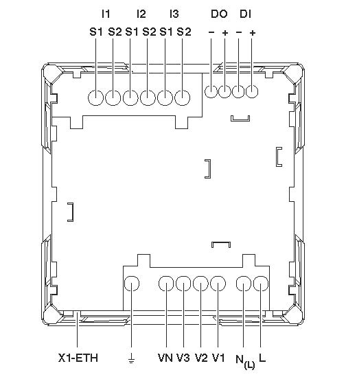
Pin assignment example
![]() Maximum tightening torque for the relevant screws: 0.5 Nm ... 0.6 Nm.
Maximum tightening torque for the relevant screws: 0.5 Nm ... 0.6 Nm.

Hint: This image shows an example of EEM-MA770
|
I1, I2, I3 |
Current measuring input, current transformer |
|
DI+, DI- |
Digital input |
|
DO+, DO- |
Digital output |
|
L, N(L) |
Supply |
|
V1, V2, V3, VN |
Voltage measuring input |
|
|
Functional ground |
|
X1-ETH |
Modbus/TCP / REST-API (RJ45) |
|
LED |
Status |
|
Optional power supply (depending on the version): |
|
|
L, N(L) |
Power supply for 230V/400V AC (L-N/L-L) |
|
24V DC +,- |
Power supply for 24V DC (+/-) |
|
Optional communication interface (depending on the version): |
|
|
LED |
Status |
|
1 x RS-485 |
RS-485 connection (Modbus/RTU) |
|
2 x ETH RJ45 |
Ethernet connection |
|
Ethernet connection |
|
Related topics
See also