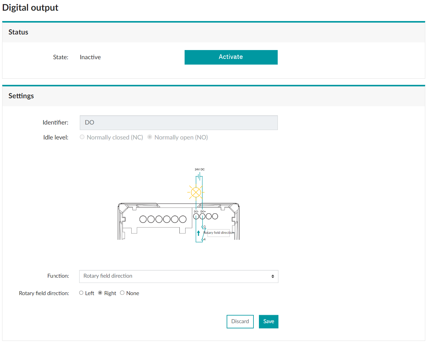
Rotary Field Direction
What you will find in this section:
The digital output complies with IEC 61131-2 Type 3. It can be configured via the web server or the Modbus communication interface.
Rotary field direction
The recognition of the rotary field direction is used to inform the digital output about the state of the application. The rotary field direction can be configured for both directions (left, right).
|
Navigation on the web server |
“Digital output, Settings, “Rotary field direction” function |

|
Status |
The “Status” area shows the current status of the alarms. |
|
Settings |
Set the alarm according to your requirements. |
|
Identifier |
The identifier can be used to assign a user-specific designation to the function. |
| Idle level |
There are two possible statuses for the idle level.
The default setting for the digital output is NO. |
|
Function |
Select the “Rotary field direction” function from the drop-down menu. |
|
Rotary field direction |
Select the appropriate rotary field direction. |