Mechanical Processing of Mounting Rails
You can use the mechanical processing mode of a mounting rail to
- define the length of the mounting rail (creates a customer-specific rail with a fixed length).
- place a single drill hole or a hole matrix on an unperforated mounting rail.
- save your customized mounting rail for reuse.
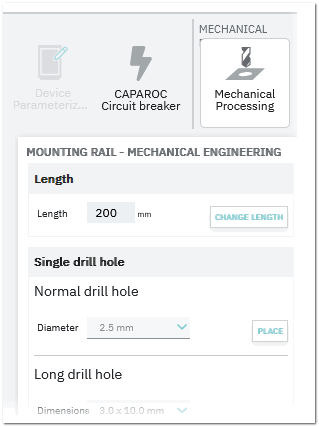
The mechanical processing mode is activated via the ribbon HOME > MECHANICAL PROCESSING or via the radial menu of the mounting rail. The mechanical processing center is then displayed instead of the Insertion Center.
This topic contains the following sections:
- Define the length of the mounting rail
- Place a single drill hole or a hole matrix on an unperforated mounting rail
- Edit drill hole / hole matrix properties
- Save and edit customized mounting rails
Define the length of the mounting rail
- Activate the manual processing mode via the HOME > MECHANICAL PROCESSING ribbon.
- Select the mounting rail in the workspace, enter the required length in the Length field in the mechanical processing center and then click the CHANGE LENGTH button.
The rail length will be modified accordingly in the workspace (creates a customer-specific rail with a fixed length; see below how to save the rail as customized rail).
Place a single drill hole or a hole matrix on an unperforated mounting rail
| Note
Drill holes and hole matrices can only be placed on unperforated mounting rails. |
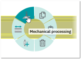
- Activate the manual processing mode via the HOME > MECHANICAL PROCESSING ribbon or select the following command in the radial menu of the mounting rail.
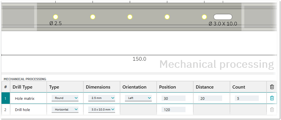
- In the mechanical processing center (see figure above), do the following:
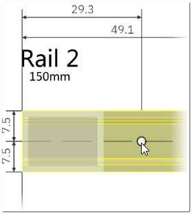
To place a... Do the following... Normal drill hole Select the required drill hole diameter from the Diameter dropdown list in the Single drill hole section, then click the PLACE button and move the cursor along the mounting rail to move the drill hole.When placing a single (normal or long) drill hole, the drill hole is attached to the mouse cursor when you drag the hole to the rail. The coordinates (in millimeters) for the hole are displayed when dragging the hole.  Example
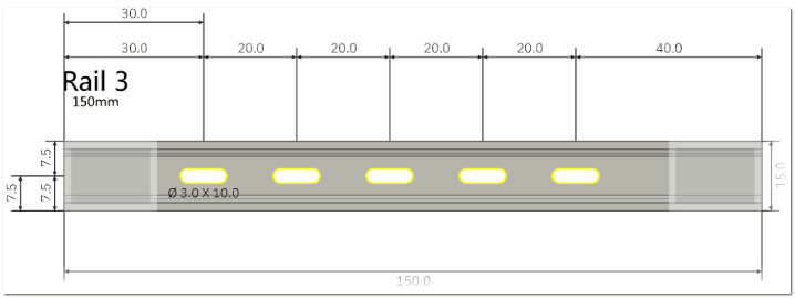
Long drill hole Select the drill hole dimensions from the Dimensions dropdown list in the Single drill hole section and the drill hole type, then click the PLACE button and move the cursor along the mounting rail to move the drill hole. (The placement behavior is the same than with a normal drill hole, see above.) Hole matrix Select the hole matrix properties in the Hole matrix section, and then click the ADD HOLE MATRIX button. The hole matrix is directly placed on the mounting rail and added to the MECHANICAL PROCESSING table in the lower area of the screen (see the following section). Example
Note
You can abort the placement operation of a single drill hole by pressing <Esc>. - For a single (normal or long) drill hole, drag the hole to the desired position and then click (the drill hole can only be placed in the horizontal middle of the rail). The hole with its property (diameter resp. dimensions and type) is displayed on the rail and added to the MECHANICAL PROCESSING table in the lower area of the screen (see the following section).
Optional: You can delete a drill hole or hole matrix by selecting the hole or hole matrix on the rail and pressing <Del> or clicking the Delete button in the radial menu and confirm the deletion.Note
If you want to place the drill hole in an invalid position, the drill hole is shown red.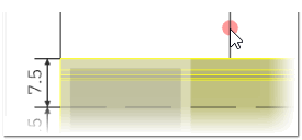
Edit drill hole / hole matrix properties
Each drill hole (single holes and hole matrices) once placed on a mounting rail is shown in the MECHANICAL PROCESSING table in the lower area of the screen. For each drill hole and hole matrix, a set of properties, such as the type, the dimensions, orientation (only available for a hole matrix), position, etc. is shown. You can edit the properties in the table by selecting a value from a dropdown list or enter a value, and pressing <Enter>. To delete a drill hole or a hole matrix, click the corresponding trash icon on the right.
Save and edit customized mounting rails
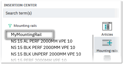
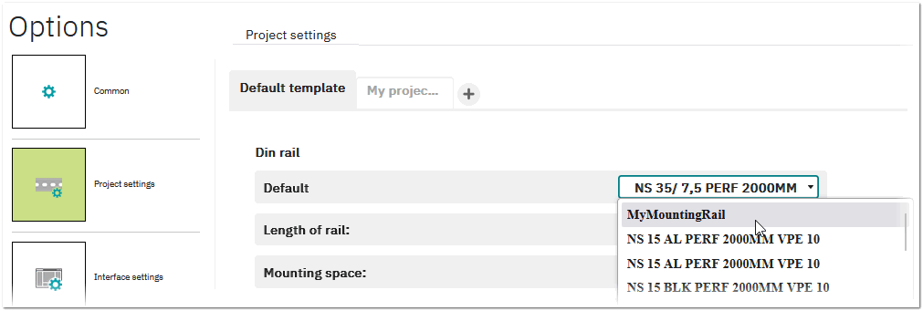
You can save your customized mounting rail to reuse it later. Once you save the customized mounting rail, the rail appears:
To save a customized rail:
- Activate the mechanical processing mode as described above and select the customized mounting rail in the workspace.
- In the mechanical processing center, click the SAVE CUSTOMIZED RAIL button in the Customized Rail section.
Note
If the selected mounting rail is already saved as a customized rail, the EDIT CUSTOMIZED RAIL button is shown (see below). - In the appearing dialog, enter an item number and a designation (mandatory fields) and, optionally, a short description and click SAVE.
To edit or delete a customized rail:
- Activate the mechanical processing mode as described above and select the customized mounting rail in the workspace.
- In the mechanical processing center, click the EDIT CUSTOMIZED RAIL button in the Customized Rail section.
Note
If the selected mounting rail is not already saved as a customized rail, the SAVE CUSTOMIZED RAIL button is shown (see above). - In the appearing dialog, edit the designation and short description and click SAVE. To remove the customized mounting rail from the list of mounting rails in the Insertion Center and the default rails (see above), click the DELETE button.