clipx ENGINEER Release Notes 2.4
This chapter describes the most important changes between versions 2.4 and 2.3 of the clipx ENGINEER software from Phoenix Contact(phoenixcontact.com/product/1272241).
The following new functions have been integrated:
Interface to MARKING system
The interface to MARKING system enables the transfer of all labels used in clipx ENGINEER, including their contents. After transfer, the data can either be displayed and further processed directly in MARKING system or saved in a file for later use in MARKING system.
Requirements for using this function:
- Version 1.2 of the MARKING system software must be installed.
- The clipx ENGINEER web link has been installed and is active. This service runs in the background and starts automatically each time the computer is started. It is necessary to ensure communication between clipx ENGINEER and MARKING system.
After successful integration, the MARKING system button can be used in the Export section of the Interface tab. Clicking this button exports all marking information and automatically opens it in MARKING system for further processing.
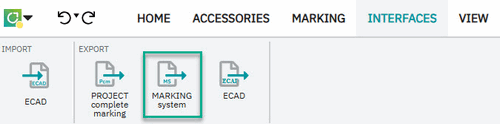
This feature ensures a seamless transition from project planning to marking and significantly reduces manual steps.
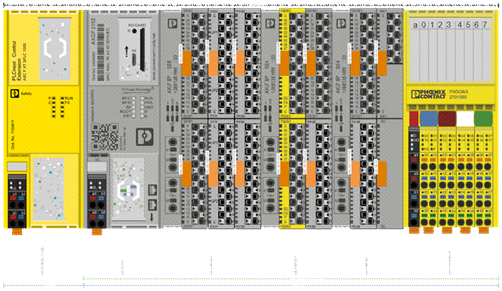
Configuration and testing of automation stations in clipx ENGINEER
The new IO PLAN wizard supports users when setting up automation stations on a DIN rail and uses the auto-correction function to check compliance with the systemic project planning rules.
Setting up a new station
To create a new automation station, the wizard is called up via the START menu - without first selecting an existing station or device. The wizard recognizes that a new station is to be set up and first queries the application area:
- PLCnext Technology: Selection of suitable controllers.
- Remote I/O systems: Selection of suitable bus couplers for fieldbus or Ethernet networks.
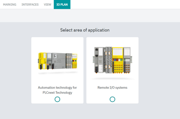
In addition, temperature ranges and required approvals can be defined so that the proposed devices meet the project requirements.
If a remote I/O station is to be set up for connection to a fieldbus or Ethernet network, the wizard offers the appropriate bus couplers for the respective communication system. Depending on the model, PLCnext controllers can be expanded with modules such as safety controller, fieldbus, PROFInet interface or machine learning functions. The selected extensions are installed directly on the DIN rail and can be supplemented with additional I/O modules.
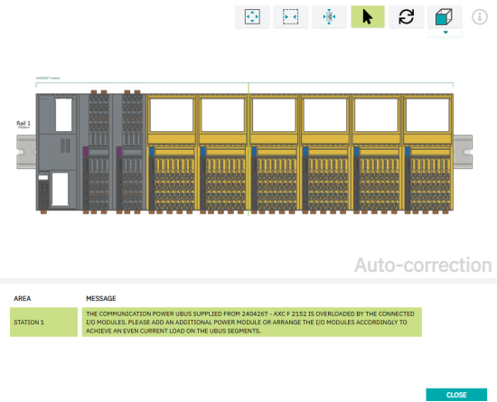
Checking the project planning rules via auto-correction
The auto-correction function in the START menu can be used to check compliance with the system configuration rules at any time. Each rule violation is displayed in the auto-correction window, including a description and correction note. When the entry is selected, the affected module in the station is highlighted and the position for the correction is marked - for example, for inserting a supply module to feed the local bus.
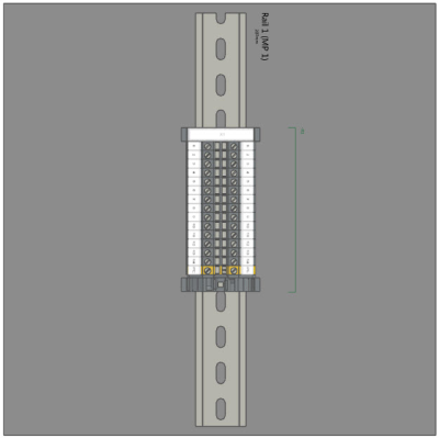
Graphical representation
If IO PLAN is called up with a module or station selected, the wizard generates a graphic layout plan. The layout plan shows the front view of the station with all the labels on the devices, plus the names of the items, the specific power consumption of this configuration and the width of the station on the DIN rail. The diagram can be copied to the clipboard as an SVG and pasted into other applications for documentation and further processing.
The complete integration of IO PLAN in clipx ENGINEER ensures intuitive operation throughout. Checking the project planning rules enables a technically correct design of the station and the graphic visualization and export function make planning and documentation easier.
EPLAN Electric P8 interface for the desktop application
With version 2.4 of clipx ENGINEER, the interface to EPLAN Electric P8 has been expanded. From now on, the target version can be specified when calling up data exchange with clipx ENGINEER.
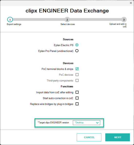
The Desktop option is now available in the drop-down menu. If Desktop is selected, the corresponding project is transferred directly to the clipx ENGINEER desktop application. To use this function, the current version of the clipx ENGINEER EPLAN interface and the desktop application are required.
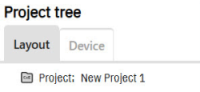
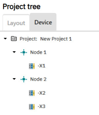
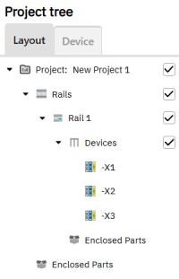
Two project tree views for better overview and navigation
The new version of clipx ENGINEER makes project organization much clearer. Two different project tree views are now available for this purpose: Layout and Device.
The Layout view depicts the physical structure of the project and provides an intuitive representation of the mechanical arrangement. When the user places a DIN rail, it appears directly in the Layout view in the project tree. If devices or items are then positioned on the DIN rail, they are displayed below the DIN rail – in the order in which they were placed, from the beginning to the end of the rail. This creates a clear, logically structured layout that reflects the actual mechanical arrangement.
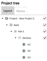
The Device view allows quick navigation to individual devices. Here, the project structure can be individually expanded by creating nodes at the desired position. In the Device view, users can also easily move placed devices to another node. The user selects the desired device in the project tree, holds down the left mouse button, and drags the device to the target node. As soon as the device is released on the new node, clipx ENGINEER automatically assigns it to the new position. In this way, the device project structure can be adapted step by step to individual requirements.
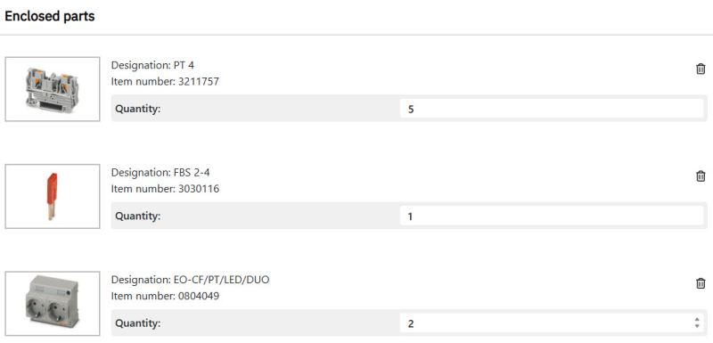
Enclosed parts
With version 2.4 of clipx ENGINEER, unmounted items can now also be added to the project as enclosed parts. Right-clicking in the cxE context menu allows you to add additional parts for project nodes or mounting rail nodes.
The list of additional parts is displayed in the workspace after clicking on the node in the project tree, allowing for easy management of additional components. Each inserted additional part is displayed in the list with the following information:
- Image
- Designation
- Item number
- Quantity
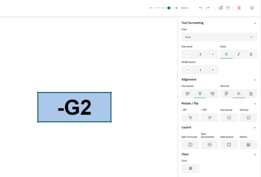
Label editor
The new label editor provides intuitive editing functions for designing customized marking solutions. Thanks to the context-sensitive menu structure, design is simple and efficient. A digital image of the customized marking solution is displayed throughout the entire editing process, helping to avoid errors. In addition, numerous new marking materials have been added, significantly increasing the selection and flexibility for implementing various marking solutions.
Once editing is complete, the marking solution can be transferred to a clipx ENGINEER project. Depending on the application and requirements, different solutions are offered for marking terminal blocks and devices.
Rotation of DIN rails on mounting panels
With the new version of clipx ENGINEER, DIN rails placed on a mounting panel can now be rotated.
Here's how it works:
- Right-click on the desired DIN rail.
- Select the desired rotation direction in the context menu.
- Then place the DIN rail in the desired position on the mounting panel. The rotated DIN rail is highlighted in color in the project tree to make the change visible.
Improvements to project documentation in clipx ENGINEER
With this update, the quality of the project documentation in clipx ENGINEER has been improved.
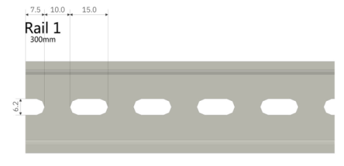
Optimized image quality
The images generated in the project documentation have been revised and their display quality has been significantly improved. As a result, technical details - especially dimensions of DIN rails and drill holes - are now much clearer and easier to read.
Additional illustration with adjusted zero cut
For DIN rails where the zero cut has been adjusted, the documentation now automatically adds an additional detailed illustration. This shows an enlarged section of the affected area and contains precise dimensions of the modified zero cut to ensure maximum transparency and traceability.