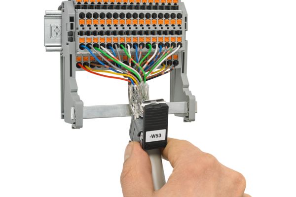
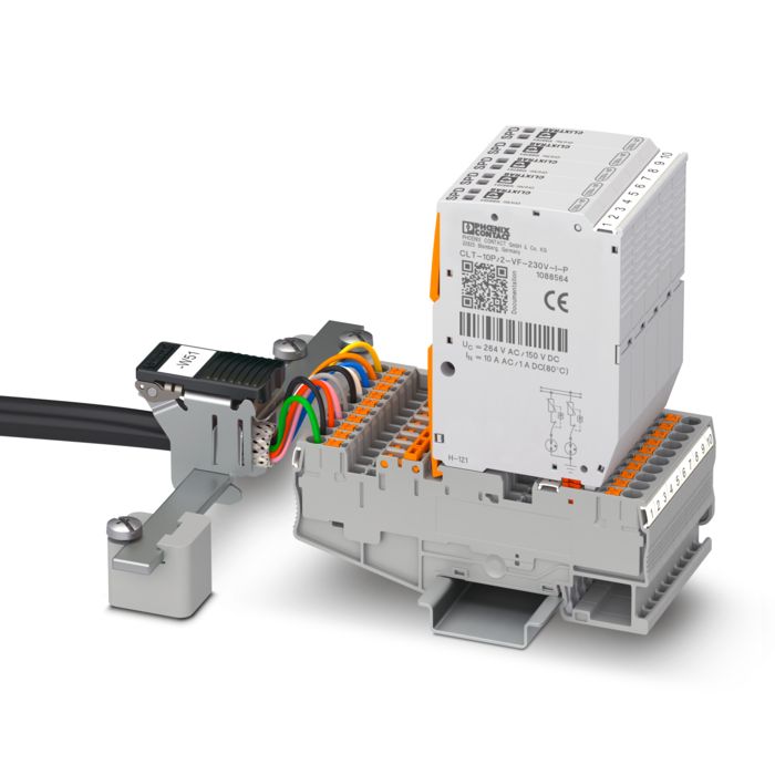
Shield connection in control cabinets Would you like to find out more about shield connection in control cabinets? If so, just contact us!

Five things you should know
- All conductors shield. A conductor that comes from the environment and is not suitably grounded will nullify the shielding.
- The entire metal housing of the control cabinet requires a professional, low-impedance grounding concept (DIN rails, mounting plates, control cabinet door, etc.).
- Do not roll up cables that are too long in the cabinet. This would create a coil, resulting in increased sensitivity to interference. The best countermeasure is to shorten the cables.
- Apply the braided shield as close to the cable entry as possible.
- Avoid pigtails. Twisting the braided shield creates an additional antenna, which actually counteracts the shielding effect.

Shielding structure with the NLS variant of the SSC shield clamp system
Shield connection in real-world applications
The shields of data transmission and MCR cables must be connected to the housing ground as soon as they enter the control cabinet. Space is tight at this point in the control cabinet due to the large number of incoming cables and lines. Only a shield clamp system that permits wiring upstream of the shield connection offers distinct advantages. Subsequent installation of the shield clamps makes work easier when space is at a premium, and thus shortens the control cabinet assembly time.
A shield clamp system consists of:
- Shield clamp
- Busbar
- Busbar support
The shield clamp is responsible for the mechanical and electrical connection of the cable shielding to the busbar. The size of the shield clamps used depends on the diameter of the cable used. The type of shielding determines the chosen busbar support, which either establishes direct contact with the housing ground or insulates the shield clamp system from the housing.

Insulated structure of a shield clamp
Direct grounding or insulated structure?
The type of shielding determines whether a structure directly contacted to the PE potential or an insulated structure is selected. For example, an insulated structure is necessary if the type of interference to be expected means that a star-shaped PE connection to a reference point in the control cabinet is required. In this case, the contact point (star point) is further away from the contact point of the shield than is the case with direct connection. The cable shielding is no longer connected via the busbar support or the DIN rail. Instead, it is connected via a pick-off terminal and a cable that is connected to the control cabinet PE. The conductor cross-section used for this connection should not be too tight. This keeps the coupling resistance described later as low as possible.

SK and SSC shield clamp systems
Flow effects
The flow effects of cables and lines are another important aspect which must be taken into consideration when connecting cable and line shields. Under the pressure exerted by the shield connection clamp, the plastic of the insulation in particular flows into the remaining spaces at the side that have not yet been filled. This is counteracted by a spring-loaded pressure plate that compensates for this effect. The spring action must be sufficient that the cable shielding is always pressed firmly against the busbar and good contact is therefore permanently ensured.

Fig. 1: Shield connection with an avoidable ground loop Fig. 2: Considerable reduction in the ground loop by shifting the pick-off terminal Fig. 3: Correct structure by grounding with a DIN rail Fig. 4: Optimal grounding with star-shaped structure
Low-impedance shield connection
The quality of a shield connection is reflected in the contact resistance between the cable shielding and system ground. With the exception of galvanic interference, all other types of interference are affected by frequency in some form or another. It is therefore not enough to simply consider the ohmic contact resistance. The inductive reactance of a shield connection, which mainly depends on the length of the path between the cable shielding and the reference ground, also plays an important role here. This is the mutual impedance of the shield connection, which is represented as a frequency-dependent curve. A very short connection is achieved by using busbar supports that are contacted directly. For longer busbars, the path to the housing ground is shortened as directly contacted busbar supports are used not just at the ends of the busbar, but are also distributed along its entire length. If an insulated structure is chosen due to the type of interference to be expected, and the connection between the cable shielding and ground is longer, it can be compensated to some extent by a correspondingly larger cable cross-section. However, a low-impedance connection is always also a low-resistance connection. This is why sufficient force must be applied to the mechanical contact points. The use of surface-coated metal parts also contributes significantly to a low-impedance connection. This is because the metals prevent tarnishing and corrosion, even in aggressive atmospheres.

Measurement of mutual impedance
Mutual impedance of shield clamp systems
To assess the quality of shield connections, the mutual impedance values for shield connection systems are represented as a function of the frequency in curve form. Such curves show the strong frequency dependence of the mutual impedance. Depending on the size of the inductive part of the mutual impedance, the curve is more or less steep toward high frequencies. This means that the length of the shield connection is directly represented in the curve, since it determines the inductive part of resistance to a large extent. The resistive part of the impedance is reflected in the height of the curve. Since noticeable differences between copper, steel, and aluminum DIN rails only occur at very high frequencies, the DIN rail material is not the determining factor for the quality of the shield connection. However, if using copper DIN rails, it should be noted that the surface tarnishes quickly. For aluminum, an oxide layer forms very quickly. Both of these properties can impair the quality of the shield connection.
Measuring method of the mutual impedance
In order to ensure accurate results, make sure that external influences are excluded when measuring the mutual impedance of a shield connection system. This means that a self-contained, externally shielded coaxial system must be used for measurement. The measuring instrument is a network analyzer which records the attenuation as a function of the frequency. The attenuation curve can be converted into an impedance curve through a simple calculation. First, the measuring system is calibrated to zero, but without the shield clamp inserted. This also compensates for errors caused by the measuring system itself. Only then is the mutual impedance recorded with the shield clamp inserted. The internal resistance of the test receiver is Ri = 50 Ω, and therefore significantly higher than the mutual impedance to be measured (Zk << 1 Ω ). As a result, current Ik is determined on a very approximate basis only by the generator voltage Ug and Ri . Both are constant, as is Ik. Measured by Zk the loss-free voltage drop U (so to speak)k is proportional to Zk.

Pigtail
Pigtail
This pigtail does not support EMC-compliant cabling. With this shielding design, the cable shielding is twisted into an additional wire and connected to ground or to the device shield. The problem with this method is that the twisted braided shield creates an additional antenna, which counteracts the actual shielding purpose.
