Monitoring active power in motors Predictive maintenance

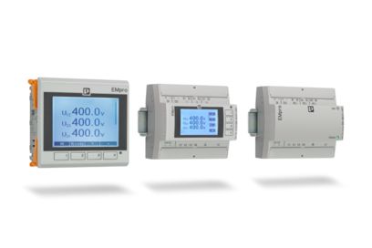
The electronic motor management from Phoenix Contact offers you all the advantages of modern active power monitoring. Every 6.6 ms, the active power consumption of a drive system or other 3-phase load is determined based on three currents, voltages, and the phase angle.
While a cos-phi monitor only detects underload states, and a motor protection relay only detects overload states, active power measurement detects all critical load states of the motor. Use Industry 4.0 and predictive maintenance for high system availability.

Optimize maintenance cycles: Safely protect and monitor the motor and system
- The recorded active power can be recorded linearly over the entire load range and evaluated accordingly
- Monitoring and diagnosis of motors for overload and underload, function, contamination, and early detection of wear and tear
- Efficient measurement of currents and phase angle (cos phi) for linear detection of all critical load conditions – in just one device

Reliable monitoring – exact and fast control
Motors and systems are monitored by means of freely parameterizable switching and signaling thresholds for overload and underload detection. By default, the thresholds are the same for both directions of rotation or are set separately for forward/reverse running.
The value used as the basis for parameterization is the consumed active power, which is independent of voltage fluctuations and the drive machine load, and therefore much more precise than merely taking the current into consideration.
If a switching threshold is violated, the motor manager initiates an emergency shutdown of the motor immediately (or with an adjustable delay time). In addition, a message is sent via an output, for example to a higher-level controller.
Example solutions

CONTACTRON motor manager, middle motor load range
Monitoring “middle motor load range”
About 80% of all motors or drives operate in the middle motor load range in which there is hardly any change to the current or cos-phi.
An overload or underload is only detected reliably by a change to the recorded active power.
In comparison to a current or cos-phi measurement, the active power contains all of the relevant electrical parameters.

CONTACTRON motor manager, optimal motor load range
Monitoring “optimum motor load range”
An ammeter is sufficient for monitoring the upper load range, since the
motor or drive is operated with an optimum cos phi. The motor or drive should ideally be designed in this way.

CONTACTRON motor manager, lower motor load range
Monitoring “lower motor load range”
Monitor a motor or drive that is used in the lower load range
for overload or underload optimally with a cos-phi monitor.

