Electrical tests for connectors and electronics housings High quality through optimum alignment of the current flow and the voltage characteristics in test batch C: During the tests, the current and voltage characteristics of PCB terminal blocks, connectors, and electronics housings are examined. We test the materials with regard to their insulation and current carrying capacity, for example, or measure the contact resistance prior to and after a test sequence.

As the third milestone prior to series release, test batch C consists of the following tests:
-
Cyclical overload test (heat-cycling test in accordance with UL 1059)
-
Cyclical aging test
-
Thermal reliability
-
Insulation resistance (UL 1703, UL27)
-
Current carrying capacity derating curve (IEC 60512-5-2)
-
Contact resistance measurement (IEC 60998-2-1)
-
High-voltage test
-
Impulse withstand voltage test (IEC 60664-1)
-
Air clearances and creepage distances
-
Resistance measurement

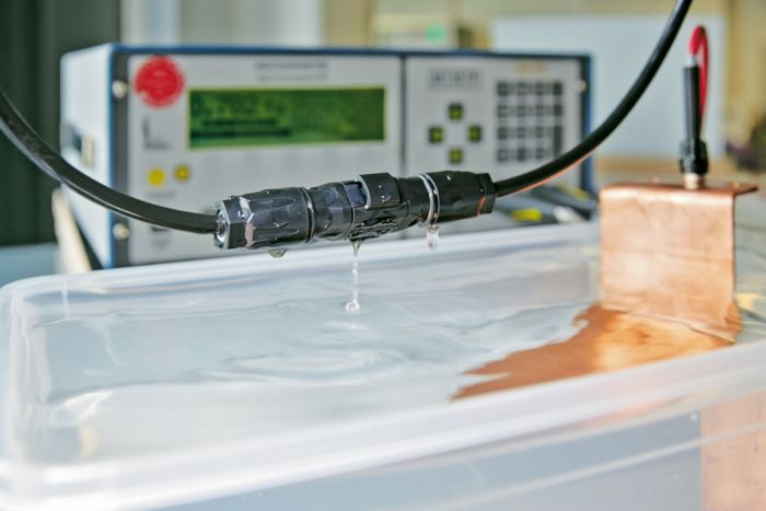
SUNCLIX connectors during the wet insulation resistance test
Wet insulation resistance test in accordance with UL 1703, UL 27
Connectors permanently in use outdoors must be able to withstand wind and weather for up to 25 years. The insulation materials used must reliably protect the users in the long term from dangerous body currents. The wet insulation resistance test offers a quantitative measure for the insulation performance of the test object. By performing the test in a conductive aqueous solution at rest, changes in the air clearances and creepage distances are identified, for example, through hairline cracks.

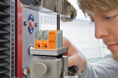
Current carrying capacity test on male connectors at various temperatures
Current carrying capacity in accordance with IEC 60512‑5‑2
The current carrying capacity of a connector is limited by the thermal properties of the materials used for the contacts and connections as well as by the insulating parts of the housing. It is dependent on the self-heating and the ambient temperature at which the component is operated. The current carrying capacity derating curve reflects the ratio of the permissible current at the temperature present.

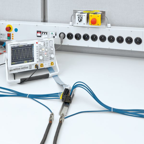
Impulse withstand voltage test in the laboratory
Impulse withstand voltage test in accordance with IEC 60664‑1
The impulse withstand voltage test provides the evidence of sufficiently large air clearances and creepage distances between two neighboring potentials. The magnitude of the test voltage is based on the rated surge voltage of the component. With three voltage surges (1.2/50 µs) per polarity, there must be no sparkovers. This test confirms that the components are safe to use in operation. The oscilloscope shows the time curve for a surge voltage pulse.

Connector voltage-drop test
Volume resistance measurement in accordance with IEC 60998‑2‑1
A gas-tight connection ensures a continuously reliable electrical contact. Determining the electrical transfer resistance, typically before and after a test sequence, assesses the high quality of a connection.


