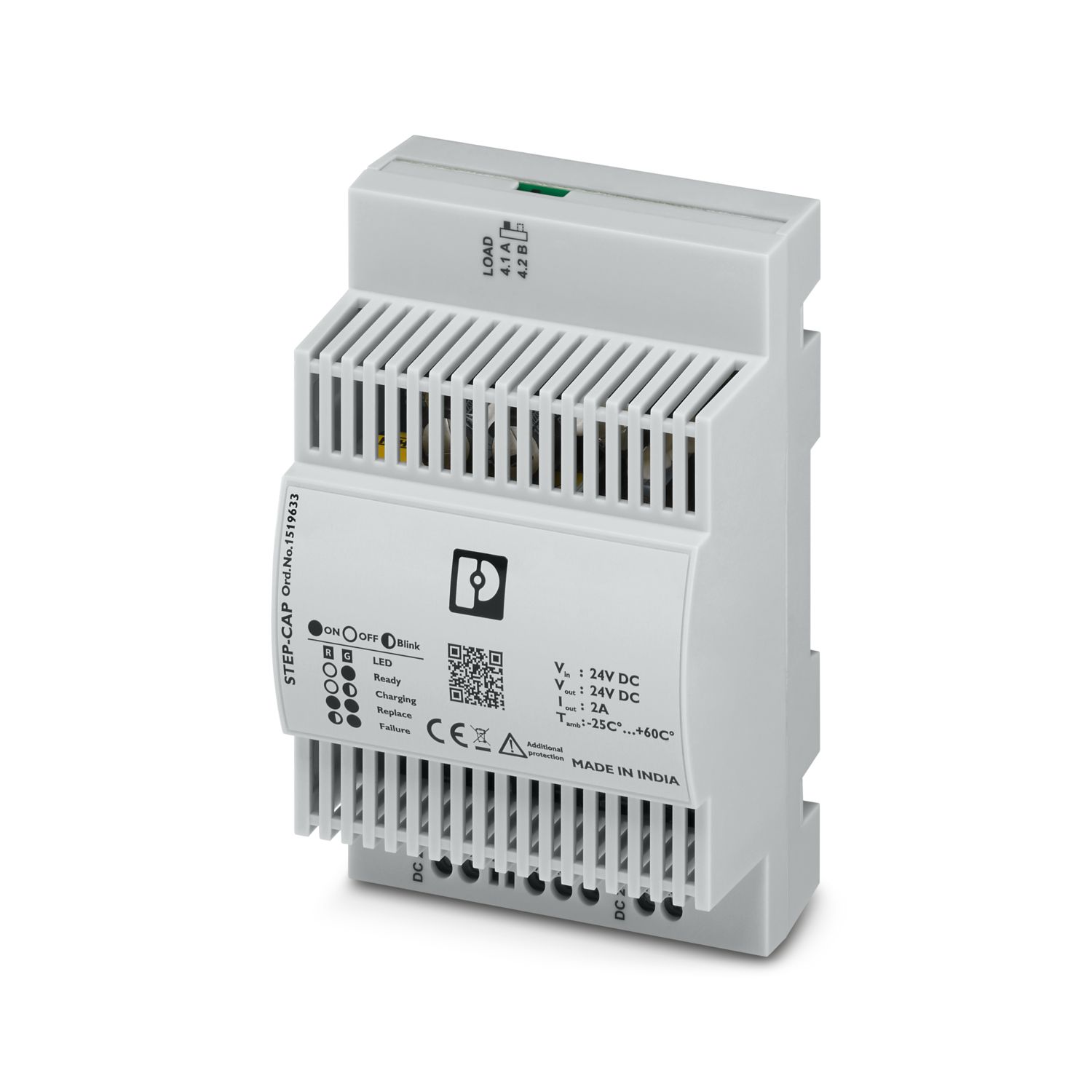
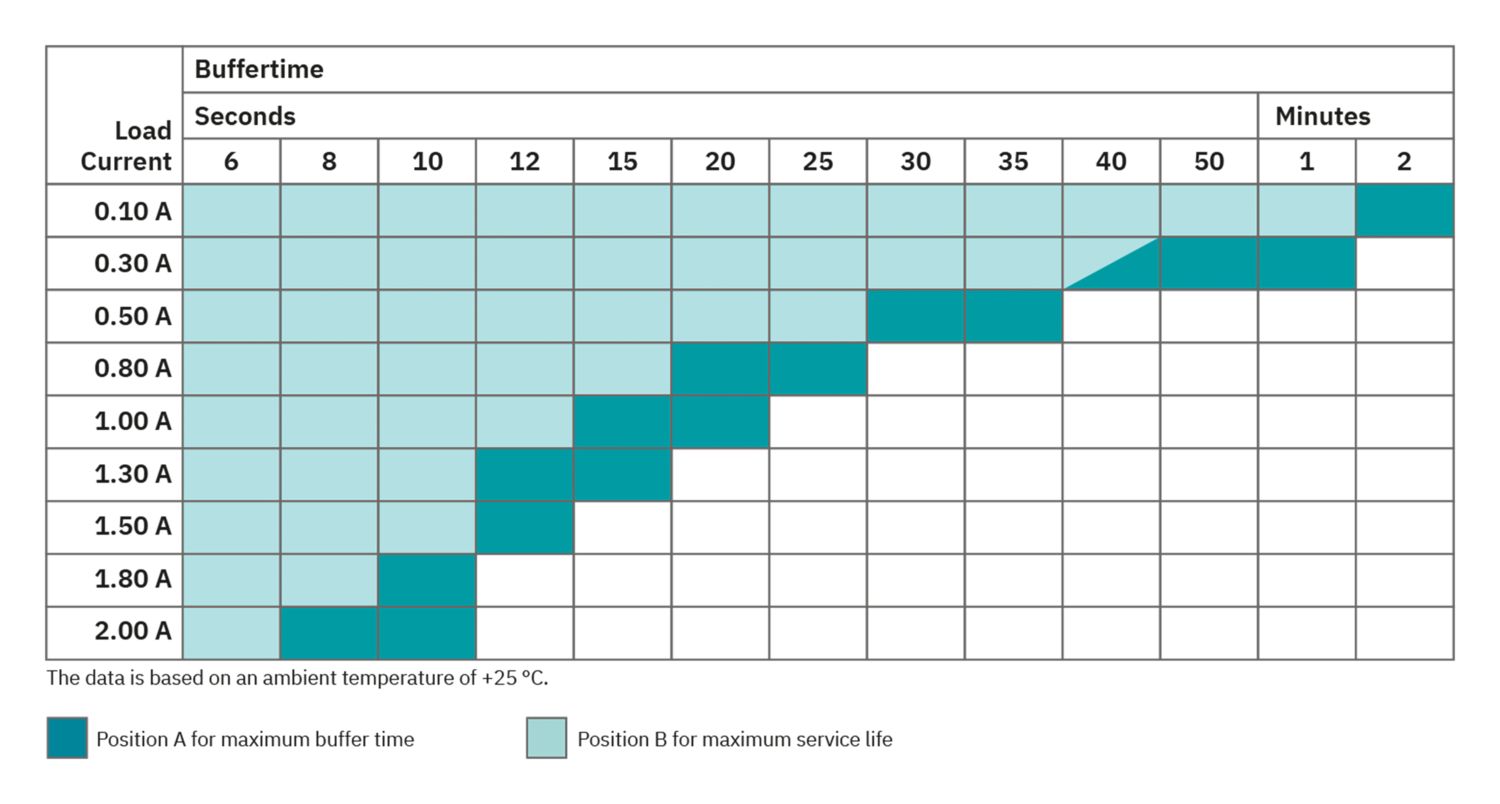
The compact STEP DC UPS with integrated capacitor can bridge power failures lasting up to one minute. The space-saving capacity module combines an electronic switch-over unit and energy storage in the same housing. The capacity module stores the energy required to bridge mains failures in maintenance-free double-layer capacitors. This ensures high system availability.
STEP-CAP/24VDC/2/0.4KJ
-
DC UPS with integrated capacity
1519633
STEP DC UPS with integrated capacitor, with maintenance-free energy storage based on double-layer capacitor, DIN rail mounting, input: 24 V DC, output: 24 V DC / 2 A / 0.4 kJ
Product details
| Input voltage | 24 V DC (SELV) |
| Input voltage range | 23.7 V DC ... 26.5 V DC |
| Fixed backup threshold | > 23.8 V DC (±2 %) |
| < 21.8 V DC (±2 %) | |
| Reverse polarity protection | yes |
| Current consumption INo-Load(UN, IOUT = 0, Icharge = 0) | 0.1 A |
| Current consumption Icharge (UN, IOUT = 0, Icharge = max) | 0.7 A |
| Power consumption PN (UN, IOUT = IN, Icharge = 0) | 50 W |
| Buffer time | 39 s (0.5 A) |
| 10 s (2 A) | |
| 29 s (0.5 A) | |
| 6 s (2 A) | |
| Charging time | 142 s (Pos. A) |
| 119 s (Pos. B) | |
| Recharging time | 71 s (Pos. A) |
| 51 s (Pos. B) | |
| Inrush current | < 15 A (At an ambient temperature of 20°C) |
| Internal input fuse | yes (3 A) |
| Dielectric strength | < 32.5 V DC |
| Efficiency | > 95 % |
| Connection in parallel | yes, for increasing the buffer period |
| Connection in series | no |
| Mains operation | |
| Output voltage | 24 V DC ±2 % (Mains operation) |
| Output current IN | 2 A |
| Output power POUT (UN, IOUT = IN) | 48 W |
| Power dissipation No load (UN, IOut = 0, ICharge = 0) | 1.4 W |
| Power dissipation Nominal load (UN, IOut = IN, ICharge = 0) | 2.3 W |
| Maximum no-load power dissipation | 1.4 W |
| Short-circuit-proof | yes (with internal 3 A fuse) |
| Idling-proof | yes |
| Battery operation | |
| Output voltage | 23 V DC ±2 % (Battery operation) |
| Output current IN | 2 A |
| Output power POUT (UN, IOUT = IN) | 48 W |
| Maximum no-load power dissipation | 1.3 W (<0.1 A) |
| Output current limit | 2.4 A ±10 % |
| Short-circuit-proof | yes |
| Idling-proof | yes |
| Input | |
| Nominal capacity | 0.4 kJ |
| Charging current | < 1 A (at 24 V DC) |
| Charging voltage | 2.8 V (Position A) |
| 2.4 V (Position B) | |
| General | |
| Capacity | 0.4 kJ |
| Energy | 270 J (Position B) |
| 416 J (Position A) | |
| Service life | 2.5 Years ... 5 Years (Position A) |
| 10 Years ... 20 Years (Position B) | |
| Storage medium | Double-layer capacitor |
| Buffer time | 39 s (0.5 A) |
| 10 s (2 A) | |
| 29 s (0.5 A) | |
| 6 s (2 A) | |
| Input | |
| Position | 1.x |
| Identification | 1.1 (+), 1.2 (-) |
| Conductor connection | |
| Connection method | Screw connection |
| rigid | 0.14 mm² ... 1.5 mm² |
| flexible | 0.14 mm² ... 1.5 mm² |
| flexible with ferrule without plastic sleeve | 0.25 mm² ... 1 mm² |
| flexible with ferrule with plastic sleeve | 0.25 mm² ... 1.5 mm² |
| rigid (AWG) | 26 ... 16 |
| Stripping length | 6 mm |
| Tightening torque | 0.5 Nm ... 0.6 Nm |
| Drive form screw head | Slotted L |
| 2-conductor connection | |
| rigid | 0.14 mm² ... 0.75 mm² |
| flexible | 0.14 mm² ... 0.75 mm² |
| flexible with TWIN ferrule with plastic sleeve | 0.5 mm² ... 0.75 mm² |
| Output | |
| Position | 2.x |
| Identification | 2.1 (+), 2.2 (-) |
| Conductor connection | |
| Connection method | Screw connection |
| rigid | 0.14 mm² ... 1.5 mm² |
| flexible | 0.14 mm² ... 1.5 mm² |
| flexible with ferrule without plastic sleeve | 0.25 mm² ... 1 mm² |
| flexible with ferrule with plastic sleeve | 0.25 mm² ... 1.5 mm² |
| rigid (AWG) | 26 ... 16 |
| Stripping length | 6 mm |
| Tightening torque | 0.5 Nm ... 0.6 Nm |
| Drive form screw head | Slotted L |
| 2-conductor connection | |
| rigid | 0.14 mm² ... 0.75 mm² |
| flexible | 0.14 mm² ... 0.75 mm² |
| flexible with TWIN ferrule with plastic sleeve | 0.5 mm² ... 0.75 mm² |
| Signal | |
| Position | 3.x |
| Identification | 3.1 (PF), 3.2 (SGnd), 3.3 (SoH) |
| Conductor connection | |
| Connection method | Screw connection |
| rigid | 0.14 mm² ... 1.5 mm² |
| flexible | 0.14 mm² ... 1.5 mm² |
| flexible with ferrule without plastic sleeve | 0.25 mm² ... 1 mm² |
| flexible with ferrule with plastic sleeve | 0.25 mm² ... 1.5 mm² |
| rigid (AWG) | 26 ... 16 |
| Stripping length | 6 mm |
| Tightening torque | 0.5 Nm ... 0.6 Nm |
| Drive form screw head | Slotted L |
| LED signaling | |
| Types of signaling | LED |
| Signal state Power Failure | |
| Connection labeling | 3.1 |
| Channel | Open collector |
| Switching contact | Transistor |
| Output voltage | 30 V |
| Output can be loaded | 10 mA |
| Signal - state assignment | low - active |
| Reference potential | SGnd |
| LED status indicator | green |
| Resistance | 10 Ω (at 24 V) |
| Signal state State of health (SOH) | |
| Connection labeling | 3.3 |
| Channel | Open collector |
| Switching contact | Transistor |
| Output voltage | 30 V |
| Output can be loaded | 10 mA |
| Signal - state assignment | low - active |
| Reference potential | SGnd |
| LED status indicator | red |
| Resistance | 10 Ω (at 24 V) |
| Signal ground SGnd | |
| Connection labeling | 3.2 |
| Switching voltage | 0 V |
| Current carrying capacity | 20 mA |
| Function | Power Failure (PF), State of Health (SOH) |
| Reference potential | SGnd |
| Insulation voltage input, output / housing | 500 V |
| Product family | STEP DC UPS with integrated capacitor |
| MTBF (IEC 61709, SN 29500) | > 500000 h (@ 25 °C) |
| Insulation characteristics | |
| Protection class | III |
| Overvoltage category | II |
| Degree of pollution | 2 |
| Item dimensions | |
| Width | 80 mm |
| Height | 125 mm |
| Depth | 60 mm |
| Installation dimensions | |
| Installation distance right/left | 0 mm / 0 mm |
| Installation distance top/bottom | 50 mm / 50 mm |
| Mounting type | DIN rail mounting |
| Mounting position | on horizontal DIN rail NS 35 in acc. with EN 60715 |
| Flammability rating according to UL 94 (housing / terminal blocks) | V0 |
| Ambient conditions | |
| Degree of protection | IP20 |
| Ambient temperature (operation) | -25 °C ... 60 °C |
| Ambient temperature (storage/transport) | -30 °C ... 70 °C |
| Maximum altitude | ≤ 2000 m |
| Climatic class | 3K3 (EN 60721) |
| Max. permissible relative humidity (operation) | < 90 % (non-condensing) |
| Shock | 30g, 18 ms |
| Vibration (operation) | 18 Hz ... 1000 Hz (1.14g RMS) |
| Electronic devices in rail vehicles | |
| Shock (operation) | 30g, 18 ms, half sine |
| Vibration (operation) | 18 Hz ... 1000 Hz |
| Electromagnetic compatibility | Conformance with EMC Directive 2014/30/EU |
| Interference emission | Interference emission in accordance with EN 61000-6-3 (residential and commercial) and EN 61000-6-4 (industrial) |
| Electrostatic discharge | |
| Standards/regulations | EN 61000-4-2 |
| Electrostatic discharge | |
| Contact discharge | 6 kV (Test Level 3) |
| Discharge in air | 8 kV (Test Level 3) |
| Comments | Criterion B |
| Electromagnetic HF field | |
| Standards/regulations | EN 61000-4-3 |
| Electromagnetic HF field | |
| Frequency range | 80 MHz ... 6 GHz |
| Test field strength | 10 V/m |
| Comments | Criterion A |
| Fast transients (burst) | |
| Standards/regulations | EN 61000-4-4 |
| Fast transients (burst) | |
| Input | 2 kV |
| Output | 2 kV |
| Signal | 1 kV |
| Surge voltage load (surge) | |
| Standards/regulations | EN 61000-4-5 |
| Surge voltage load (surge) | |
| Input | symmetrical 0.5 kV |
| symmetrical 1 kV | |
| Output | symmetrical 0.5 kV |
| asymmetrical 1 kV | |
| Signal | asymmetrical 1 kV |
| Comments | Criterion B |
| Conducted interference | |
| Standards/regulations | EN 61000-4-6 |
| Typical deviation from the measuring range final value | 80 % |
| Conducted interference | |
| Frequency range | 150 kHz ... 80 MHz |
| Comments | Criterion A |
| Voltage | 10 V |
| Criteria | |
| Criterion A | Normal operating behavior within the specified limits. |
| Criterion B | Temporary impairment to operational behavior that is corrected by the device itself. |
| Criterion C | Temporary adverse effects on the operating behavior, which the device corrects automatically or which can be restored by actuating the operating elements. |
| Item number | 1519633 |
| Packing unit | 1 pc |
| Minimum order quantity | 1 pc |
| Sales key | CMUSC3 |
| Product key | CMUSC3 |
| GTIN | 4063151987343 |
| Weight per piece (including packing) | 313,3 g |
| Weight per piece (excluding packing) | 233 g |
| Customs tariff number | 85322900 |
| Country of origin | IN |
ECLASS
| ECLASS-13.0 | 27040705 |
| ECLASS-15.0 | 27040705 |
ETIM
| ETIM 9.0 | EC000382 |
UNSPSC
| UNSPSC 21.0 | 39121000 |
| EU RoHS | |
| Fulfills EU RoHS substance requirements | Yes |
| Exemption | 7(a), 7(c)-I |
| China RoHS | |
| Environment friendly use period (EFUP) |
EFUP-25
An article-related China RoHS declaration table can be found in the download area for the respective article under "Manufacturer declaration". For all articles with EFUP-E, no China RoHS declaration table issued and required.
|
| EU REACH SVHC | |
| REACH candidate substance (CAS No.) | Lead (CAS: 7439-92-1) |
| SCIP | e51fbe43-fedd-4971-a6e7-856a84198cb2 |
| EF3.1 Climate Change | |
| CO2e kg | 8,121 kg CO2e |
Compatible products
Your advantages
Space savings, thanks to the compact design
Maintenance-free double layer condensators
High system availability due to long capacitor service life
Modular and flexible for various applications: -25°C ... +60°C
PHOENIX CONTACT A/S
Hammerholmen 43C, 1. tv. 2650 Hvidovre