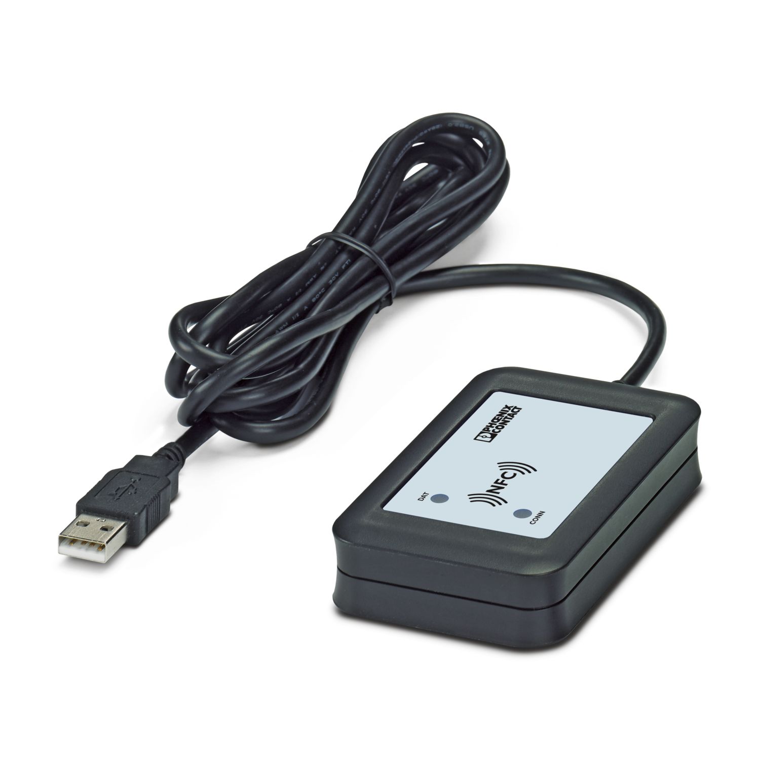
The fourth generation of the high-performance QUINT POWER power supplies ensures superior system availability by means of new functions. Signaling thresholds and characteristic curves can be individually adjusted via the NFC interface.
The unique SFB technology and preventive function monitoring of the QUINT POWER power supply increase the availability of your application.
QUINT4-PS/1AC/24DC/10/+
-
Power supply
2904616
Electrical number:
960908029
Electrical number:
960908029
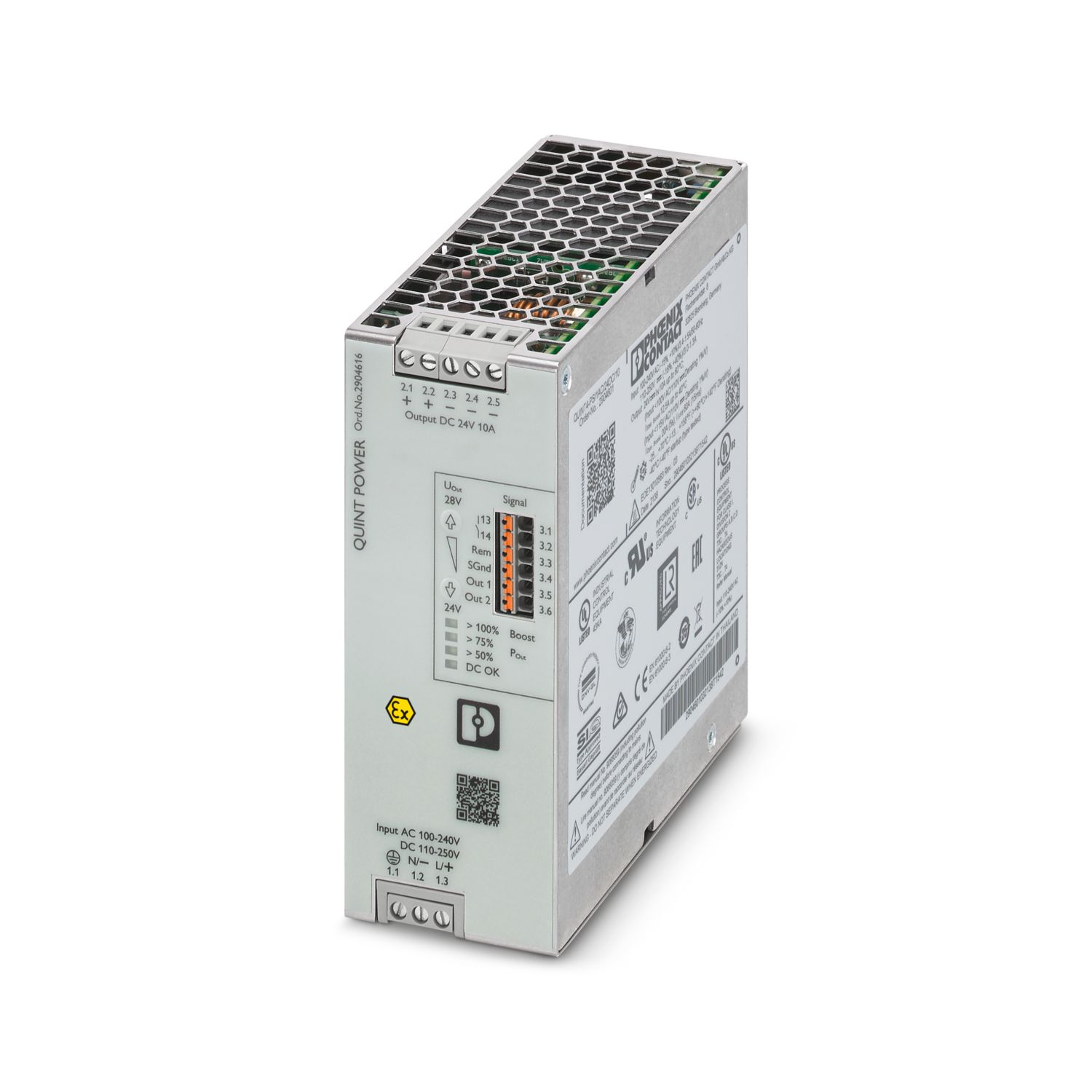
Primary-switched QUINT POWER supply for DIN rail mounting, with selectable output characteristic curve and SFB (Selective Fuse Breaking) Technology, protective coating and integrated decoupling MOSFET, input: 1-phase, output: 24 V DC / 10 A
Free download available.
Downloads
Product details
Control input (configurable) Rem | Output power ON/OFF (SLEEP MODE) |
Default | Output power ON (>40 kΩ/24 V DC/open bridge between Rem and SGnd) |
AC operation | |
Network type | Star network |
Input voltage | min. 77 V DC |
Nominal input voltage range | 100 V AC ... 240 V AC |
Input voltage range | 100 V AC ... 240 V AC -15 % ... +10 % |
Derating | < 100 V AC (1 %/V) |
Electric strength, max. | 300 V AC 60 s |
Typical national grid voltage | 120 V AC |
230 V AC | |
Voltage type of supply voltage | AC |
Inrush current | typ. 15 A (at 25 °C) |
Inrush current integral (I2t) | < 0.9 A2s |
Inrush current limitation | 15 A (after 1 ms) |
AC frequency range | 50 Hz ... 60 Hz -10 % ... +10 % |
Frequency range (fN) | 50 Hz ... 60 Hz -10 % ... +10 % |
16.7 Hz (acc. to EN 50163) | |
Mains buffering time | typ. 53 ms (120 V AC) |
typ. 55 ms (230 V AC) | |
Current consumption | 3.4 A (100 V AC) |
2.8 A (120 V AC) | |
1.5 A (230 V AC) | |
1.5 A (240 V AC) | |
Nominal power consumption | 274 VA |
Protective circuit | Transient surge protection; Varistor, gas-filled surge arrester |
Power factor (cos phi) | 0.94 |
Switch-on time | < 1 s |
Typical response time | 300 ms (from SLEEP MODE) |
Input fuse | 8 A (slow-blow, internal) |
Recommended breaker for input protection | 10 A ... 16 A (Characteristic B, C, D, K or comparable) |
Discharge current to PE | < 3.5 mA |
0.7 mA (264 V AC, 60 Hz) | |
DC operation | |
Input voltage | min. 77 V DC |
Nominal input voltage range | 110 V DC ... 250 V DC |
Input voltage range | 110 V DC ... 250 V DC -18 % ... +40 % |
Derating | < 110 V DC (1 %/V) |
Voltage type of supply voltage | DC |
Current consumption | 3 A (110 V DC) |
1.3 A (250 V DC) |
Efficiency | typ. 92.8 % (120 V AC) |
typ. 93.8 % (230 V AC) | |
Output characteristic | U/I Advanced |
Smart HICCUP | |
FUSE MODE | |
Nominal output voltage | 24 V DC |
Setting range of the output voltage (USet) | 24 V DC ... 28 V DC (constant capacity) |
Nominal output current (IN) | 10 A |
Static Boost (IStat.Boost) | 12.5 A |
Dynamic Boost (IDyn.Boost) | 20 A (5 s) |
Selective Fuse Breaking (ISFB) | 60 A (15 ms) |
Magnetic circuit breaker tripping | A1...A6 / B2...B6 / C1...C3 / Z1...Z6 |
Derating | > 60 °C ... 70 °C (2.5 %/K) |
Feedback voltage resistance | ≤ 35 V DC |
Protection against overvoltage at the output (OVP) | < 30 V DC (double protection with shut off within 20 ms) |
Control deviation | < 0.5 % (Static load change 10 % ... 90 %) |
< 4 % (Dynamic load change 10 % ... 90 %, (10 Hz)) | |
< 0.25 % (change in input voltage ±10 %) | |
Residual ripple | < 50 mVPP (with nominal values) |
Short-circuit-proof | yes |
No-load proof | yes |
Output power | 240 W |
300 W | |
480 W | |
Apparent power | 336 VA (120 V, UOUT = 24 V, IOUT = stat. Boost) |
345 VA (230 V, UOUT = 24 V, IOUT = stat. Boost) | |
Maximum no-load power dissipation | < 4 W (120 V AC) |
< 4 W (230 V AC) | |
Power loss nominal load max. | < 19 W (120 V AC) |
< 16 W (230 V AC) | |
Power dissipation SLEEP MODE | < 3 W (120 V AC) |
< 3 W (230 V AC) | |
Crest factor | typ. 1.57 (120 V AC) |
typ. 1.59 (230 V AC) | |
Rise time | < 100 ms (UOut = 10 % ... 90 %) |
Connection in parallel | yes, for redundancy and increased capacity |
Connection in series | yes |
Signal | |
Signal ground SGnd | Reference potential for Out1, Out2, and Rem |
Signal Out 1 (configurable) | |
Digital | 24 V DC 20 mA |
Default | 24 V DC 20 mA 24 V DC for UOut > 0.9 x USet |
Signal Out 2 (configurable) | |
Digital | 24 V DC 20 mA |
Analog | 4 mA ... 20 mA ±5 % (Load ≤400 Ω) |
Default | 24 V DC 20 mA 24 V DC for POut < PN |
Signal relay 13/14 (configurable) | |
Default | closed (Uout > 0.9 USet) |
Digital | 24 V DC 1 A |
30 V AC/DC 0.5 A |
Input | |
Connection method | Screw connection |
Conductor cross section, rigid min. | 0.2 mm² |
Conductor cross section, rigid max. | 2.5 mm² |
Conductor cross section flexible min. | 0.2 mm² |
Conductor cross section flexible max. | 2.5 mm² |
Single conductor/flexible terminal point with ferrule with plastic sleeve, min. | 0.25 mm² |
Single conductor/flexible terminal point with ferrule with plastic sleeve, max. | 2.5 mm² |
Single conductor/flexible terminal point with ferrule without plastic sleeve, min. | 0.25 mm² |
Single conductor/flexible terminal point with ferrule without plastic sleeve, max. | 2.5 mm² |
Conductor cross section AWG min. | 24 |
Conductor cross section AWG max. | 14 |
Stripping length | 6.5 mm |
Tightening torque, min | 0.5 Nm |
Tightening torque max | 0.6 Nm |
Output | |
Connection method | Screw connection |
Conductor cross section, rigid min. | 0.2 mm² |
Conductor cross section, rigid max. | 2.5 mm² |
Conductor cross section flexible min. | 0.2 mm² |
Conductor cross section flexible max. | 2.5 mm² |
Single conductor/flexible terminal point with ferrule with plastic sleeve, min. | 0.25 mm² |
Single conductor/flexible terminal point with ferrule with plastic sleeve, max. | 2.5 mm² |
Single conductor/flexible terminal point with ferrule without plastic sleeve, min. | 0.25 mm² |
Single conductor/flexible terminal point with ferrule without plastic sleeve, max. | 2.5 mm² |
Conductor cross section AWG min. | 24 |
Conductor cross section AWG max. | 14 |
Stripping length | 6.5 mm |
Tightening torque, min | 0.5 Nm |
Tightening torque max | 0.6 Nm |
Signal | |
Connection method | Push-in connection |
Conductor cross section, rigid min. | 0.2 mm² |
Conductor cross section, rigid max. | 1.5 mm² |
Conductor cross section flexible min. | 0.2 mm² |
Conductor cross section flexible max. | 1.5 mm² |
Single conductor/flexible terminal point with ferrule with plastic sleeve, min. | 0.2 mm² |
Single conductor/flexible terminal point with ferrule with plastic sleeve, max. | 0.75 mm² |
Single conductor/flexible terminal point with ferrule without plastic sleeve, min. | 0.2 mm² |
Single conductor/flexible terminal point with ferrule without plastic sleeve, max. | 1.5 mm² |
Conductor cross section AWG min. | 24 |
Conductor cross section AWG max. | 16 |
Stripping length | 8 mm |
Types of signaling | LED |
Floating signal contact | |
Active signal output Out1 (digital, configurable) | |
Active signal output Out2 (analog, configurable) | |
Remote contact | |
Signal ground SGnd | |
Signal output | |
POut | > 100 % (LED lights up yellow, output power > 240 W) |
> 75 % (LED lights up green, output power > 180 W) | |
> 50 % (LED lights up green, output power > 120 W) | |
UOut | > 0.9 x USet (LED lights up green) |
< 0.9 x USet (LED flashes green) |
Number of phases | 1 |
Insulation voltage input/output | 4 kV AC (type test) |
2 kV AC (routine test) | |
Switching frequency | 90.00 kHz ... 110.00 kHz (Auxiliary converter stage) |
50.00 kHz ... 245.00 kHz (Main converter stage) | |
35.00 kHz ... 700.00 kHz (PFC stage) |
Product type | Power supply |
Product family | QUINT POWER |
MTBF (IEC 61709, SN 29500) | > 1165000 h (25 °C) |
> 700000 h (40 °C) | |
> 321000 h (60 °C) | |
Environmental protection directive | RoHS Directive 2011/65/EU |
WEEE | |
Reach | |
Insulation characteristics | |
Protection class | I |
Degree of pollution | 2 |
Life expectancy (electrolytic capacitors) | |
Current | 5 A |
Temperature | 40 °C |
Time | 247000 h |
Additional text | 120 V AC |
Life expectancy (electrolytic capacitors) | |
Current | 5 A |
Temperature | 40 °C |
Time | 247000 h |
Additional text | 230 V AC |
Life expectancy (electrolytic capacitors) | |
Current | 10 A |
Temperature | 25 °C |
Time | 288000 h |
Additional text | 120 V AC |
Life expectancy (electrolytic capacitors) | |
Current | 10 A |
Temperature | 25 °C |
Time | 345000 h |
Additional text | 230 V AC |
Life expectancy (electrolytic capacitors) | |
Current | 10 A |
Temperature | 40 °C |
Time | 112000 h |
Additional text | 120 V AC |
Life expectancy (electrolytic capacitors) | |
Current | 10 A |
Temperature | 40 °C |
Time | 138000 h |
Additional text | 230 V AC |
Width | 50 mm |
Height | 130 mm |
Depth | 125 mm |
Installation dimensions | |
Installation distance right/left | 5 mm / 5 mm |
Installation distance top/bottom | 50 mm / 50 mm |
Alternative assembly | |
Width | 122 mm |
Height | 130 mm |
Depth | 53 mm |
Mounting type | DIN rail mounting |
Assembly note | alignable: PN ≥50%, 5 mm horizontally, 15 mm next to active components, 50 mm vertically alignable: PN <50%, 0 mm horizontally, 40 mm vertically top, 20 mm vertically bottom |
Mounting position | horizontal DIN rail NS 35, EN 60715 |
With protective coating | yes |
Flammability rating according to UL 94 (housing / terminal blocks) | V0 |
Housing material | Metal |
Hood version | Stainless steel X6Cr17 |
Side element version | Aluminum |
Ambient conditions | |
Degree of protection | IP20 |
Ambient temperature (operation) | -40 °C ... 75 °C (> 60 °C Derating: 2,5 %/K) |
Ambient temperature (storage/transport) | -40 °C ... 85 °C |
Maximum altitude | ≤ 5000 m (> 2000 m, observe derating) |
Climatic class | 3K22 (in accordance with EN 60721-3-3) |
Max. permissible relative humidity (operation) | ≤ 100 % (at 25 °C, non-condensing) |
Shock | 18 ms, 30g, in each space direction (according to IEC 60068-2-27) |
Vibration (operation) | 5 Hz ... 100 Hz resonance search 2.3g, 90 min., resonance frequency 2.3g, 90 min. (according to DNV GL Class C) |
Temp code | T4 (-40 ... +75 °C; > 60 °C, Derating: 2,5 %/K) |
Rail applications | EN 50121-3-2 |
EN 50121-4 | |
EN 50121-5 | |
EN 50163 | |
IEC 62236-3-2 | |
IEC 62236-4 | |
IEC 62236-5 | |
EN 50155 | |
EN 45545-2 (HL3) | |
EN 61373 (Class 1B) | |
HART FSK Physical Layer Test Specification Compliance | Output voltage UOut compliant |
Standard – Limitation of mains harmonic currents | EN 61000-3-2 |
Standard - Electrical safety | IEC 61010-2-201 (SELV) |
Explosive atmosphere | IEC 60079-0 |
IEC 60079-7 | |
IEC 60079-11 | |
IEC 60079-15 | |
Standard – Safety extra-low voltage | IEC 61010-1 (SELV) |
IEC 61010-2-201 (PELV) | |
Standard - Safe isolation | IEC 61558-2-16 |
IEC 61010-2-201 | |
Standard - safety for equipment for measurement, control, and laboratory use | IEC 61010-1 |
Battery charging | DIN 41773-1 |
Noxious gas test | ANSI/ISA 71.04-2013 G3 Harsh Group A |
Approval - requirement of the semiconductor industry with regard to mains voltage dips | SEMI F47-0706, EN 61000-4-11 |
Overvoltage category | |
EN 61010-1 | II (≤ 5000 m) |
EN 62477-1 | III (≤ 2000 m) |
EN 61558-2-16 | II (≤ 5000 m) |
Fire protection in rail vehicles | |
Standard designation | Fire protection in rail vehicles |
Standards/specifications | EN 45545-2 (HL3) |
CSA | CAN/CSA-C22.2 No. 61010-2-201 |
CSA-C22.2 No. 107.1-16 | |
Shipbuilding approval | DNV, BV, LR |
SIQ | CB-Scheme (IEC 61010-1, IEC 61010-2-201) |
UL approvals | UL Listed UL 508 |
UL 121201 & CSA C22.2 No. 213-17 Class I, Division 2, Groups A, B, C, D T4 (Hazardous Location) | |
Conformity/Approvals | |
ATEX | SIQ 22 ATEX 245 X |
II 3 G Ex ec ic nC IIC T4 Gc | |
IECEx | IECEx SIQ 22.0001X |
Ex ec ic nC IIC T4 Gc | |
Functional Safety in accordance with IEC 61508 | SIL 3 |
Electromagnetic compatibility | Conformance with EMC Directive 2014/30/EU |
Low Voltage Directive | Conformance with Low Voltage Directive 2014/35/EC |
EMC requirements for noise emission | EN 61000-6-3 |
EN 61000-6-4 | |
EMC requirements for noise immunity | EN 61000-6-1 |
EN 61000-6-2 | |
EMC requirements, power plant | EN 61850-3 |
EN 61000-6-5 | |
EMC requirements for power supply | IEC 61850-3 (G,H) |
EN 61000-6-5 (switching devices) | |
Conducted noise emission | |
Standards/regulations | EN 55016 |
EN 61000-6-3 (Class B) | |
Noise emission | |
Standards/regulations | Additional basic standard EN 61000-6-5 (immunity in switching devices), IEC/EN 61850-3 (power supply) |
Noise emission | |
Standards/regulations | EN 55016 |
EN 61000-6-3 (Class B) | |
DNV GL conducted noise emissions | |
DNV | Class B |
Additional text | Bridge and deck area |
DNV GL noise radiation | |
DNV | Class B |
Additional text | Bridge and deck area |
Harmonic currents | |
Standards/regulations | EN 61000-3-2 |
EN 61000-3-2 (Class A) | |
Frequency range | 0 kHz ... 2 kHz |
Flicker | |
Standards/regulations | EN 61000-3-3 |
EN 61000-3-3 | |
Frequency range | 0 kHz ... 2 kHz |
Electrostatic discharge | |
Standards/regulations | EN 61000-4-2 |
Electrostatic discharge | |
Contact discharge | 8 kV (Test Level 4) |
Discharge in air | 15 kV (Test Level 4) |
Comments | Criterion A |
Electromagnetic HF field | |
Standards/regulations | EN 61000-4-3 |
Electromagnetic HF field | |
Frequency range | 80 MHz ... 1 GHz |
Test field strength | 20 V/m (Test Level 3) |
Frequency range | 1 GHz ... 6 GHz |
Test field strength | 10 V/m (Test Level 3) |
Comments | Criterion A |
Fast transients (burst) | |
Standards/regulations | EN 61000-4-4 |
Fast transients (burst) | |
Input | 4 kV (Test Level 4 - asymmetrical) |
Output | 4 kV (Test Level 4 - asymmetrical) |
Signal | 4 kV (Test Level 4 - asymmetrical) |
Comments | Criterion A |
Surge voltage load (surge) | |
Standards/regulations | EN 61000-4-5 |
Surge voltage load (surge) | |
Input | typ. 3 kV (Test Level 4 - symmetrical) |
typ. 6 kV (Test Level 4 - asymmetrical) | |
Output | 1 kV (Test Level 3 - symmetrical) |
2 kV (Test Level 3 - asymmetrical) | |
Signal | 4 kV (Test Level 4 - asymmetrical) |
Comments | Criterion A |
Conducted interference | |
Standards/regulations | EN 61000-4-6 |
Conducted interference | |
Input/output/signal | asymmetrical |
Frequency range | 0.15 MHz ... 80 MHz |
Comments | Criterion A |
Voltage | 10 V (Test Level 3) |
Power frequency magnetic field | |
Standards/regulations | EN 61000-4-8 |
Frequency | 16.7 Hz |
50 Hz | |
60 Hz | |
Test field strength | 100 A/m |
Additional text | 60 s |
Comments | Criterion A |
Frequency | 50 Hz |
60 Hz | |
Frequency range | 50 Hz ... 60 Hz |
Test field strength | 1 kA/m |
Additional text | 3 s |
Frequency | 0 Hz |
Test field strength | 300 A/m |
Additional text | DC, 60 s |
Voltage dips | |
Standards/regulations | EN 61000-4-11 |
Voltage | 230 V AC |
Frequency | 50 Hz |
Voltage dip | 70 % |
Number of periods | 0.5 / 1 / 25 / 30 periods |
Additional text | Test Level 2 |
Comments | Criterion A: 0.5 / 1 / 25 / 30 periods |
Voltage dip | 40 % |
Number of periods | 5 / 10 / 50 periods |
Additional text | Test Level 2 |
Comments | Criterion A |
Voltage dip | 0 % |
Number of periods | 0,5 / 1 / 5 / 50 / 250 periods |
Additional text | Test Level 2 |
Comments | Criterion A: 0.5 / 1 period Criterion B: 5 / 50 / 250 periods |
Pulse-shape magnetic field | |
Standards/regulations | EN 61000-4-9 |
Test field strength | 1000 A/m |
Comments | Criterion A |
Attenuated sinusoidal oscillations (ring wave) | |
Standards/regulations | EN 61000-4-12 |
Input | 2 kV (Test Level 4 - symmetrical) |
4 kV (Test Level 4 - asymmetrical) | |
Comments | Criterion A |
Asymmetrical conducted disturbance variables | |
Standards/regulations | EN 61000-4-16 |
Test level 1 | 15 Hz 150 Hz (Test Level 4) |
Voltage | 30 V 3 V |
Test level 2 | 150 Hz 1.5 kHz (Test Level 4) |
Voltage | 3 V |
Test level 3 | 1.5 kHz 15 kHz (Test Level 4) |
Voltage | 3 V 30 V |
Test level 4 | 15 kHz 150 kHz (Test Level 4) |
Voltage | 30 V |
Test level 5 | 16.7 Hz 50 Hz 60 Hz (Test Level 4) |
Voltage | 30 V (10 s) |
Test level 6 | 150 Hz 180 Hz (Test Level 4) |
Voltage | 30 V (10 s) |
Test level 7 | 16.7 Hz 50 Hz 60 Hz (Test Level 4) |
Voltage | 300 V (1 s) |
Comments | Criterion A |
Attenuated oscillating wave | |
Standards/regulations | EN 61000-4-18 |
Input, output (test level 1) | 100 kHz 1 MHz (Test Level 3 - symmetrical) |
Voltage | 1 kV |
Input, output (test level 2) | 10 MHz (Test Level 3 - asymmetrical) |
Voltage | 2 kV |
Input, output (test level 3) | 100 kHz 1 MHz (Test Level 3 - asymmetrical) |
Voltage | 2.5 kV |
Signals (test level 1) | 100 kHz 1 MHz (Test Level 3 - symmetrical) |
Voltage | 1 kV |
Signals (test level 2) | 100 kHz 1 MHz (Test Level 3 - asymmetrical) |
Voltage | 2.5 kV |
Comments | Criterion A |
Attenuated oscillating magnetic field | |
Standards/regulations | EN 61000-4-10 |
Test field strength | 100 A/m |
Test level 1 | 100 kHz |
Test field strength | 100 A/m |
Test level 2 | 1 MHz |
Comments | Criterion A |
Criteria | |
Criterion A | Normal operating behavior within the specified limits. |
Criterion B | Temporary impairment to operational behavior that is corrected by the device itself. |
Criterion C | Temporary adverse effects on the operating behavior, which the device corrects automatically or which can be restored by actuating the operating elements. |
Item number | 2904616 |
Packing unit | 1 pc |
Minimum order quantity | 1 pc |
Sales key | CMPI13 |
Product key | CMPI13 |
GTIN | 4063151023478 |
Weight per piece (including packing) | 1’156.5 g |
Weight per piece (excluding packing) | 897 g |
Customs tariff number | 85044000 |
Country of origin | TH |
ECLASS
ECLASS-13.0 | 27040701 |
ETIM
ETIM 9.0 | EC002540 |
UNSPSC
UNSPSC 21.0 | 39121000 |
cULus Listed
Approval ID: FILE E 123528Type approved
Approval ID: SI-SIQ BG 005/108LR
Approval ID: LR22472797TAcCSAus
Approval ID: 80128434BV
Approval ID: 44621/B0 BVBIS Licence Document
Approval ID: R-41268801SEMI F47
Approval ID: SEMI F47CoC / Compliance Statement
Approval ID: 24PP124-01_0IECEx
Approval ID: IECEx SIQ 22.0001XATEX
Approval ID: SIQ 22 ATEX 245 XUKCA-EX
Approval ID: EXV22UKEX1334XcULus Listed
Approval ID: FILE E 199827CCC
Approval ID: 2022122303116030EU RoHS | |
Fulfills EU RoHS substance requirements | Yes |
Exemption | 6(c), 7(a), 7(c)-I |
China RoHS | |
Environment friendly use period (EFUP) |
EFUP-25
An article-related China RoHS declaration table can be found in the download area for the respective article under "Manufacturer declaration". For all articles with EFUP-E, no China RoHS declaration table issued and required.
|
EU REACH SVHC | |
REACH candidate substance (CAS No.) | Lead (CAS: 7439-92-1) |
SCIP | 13036d76-0847-4a71-85b7-1229aab84221 |
Compatible products
-
UWA 182/52 - Mounting adapter 2938235
-
UWA 130 - Mounting adapter 2901664
-
TWN4 MIFARE NFC USB ADAPTER - Programming adapter 2909681
-
PLT-SEC-T3-230-FM-UT - Type 3 surge protection device 2907919
-
CBMC E4 24DC/1-4A NO - Electronic circuit breaker 2906031
-
CBMC E4 24DC/1-10A NO - Electronic circuit breaker 2906032
-
CBMC E4 24DC/1-4A+ IOL - Electronic circuit breaker 2910410
-
CBMC E4 24DC/1-10A IOL - Electronic circuit breaker 2910411
-
CBM E4 24DC/0.5-10A NO-R - Electronic circuit breaker 2905743
-
CBM E8 24DC/0.5-10A NO-R - Electronic circuit breaker 2905744
Your advantages
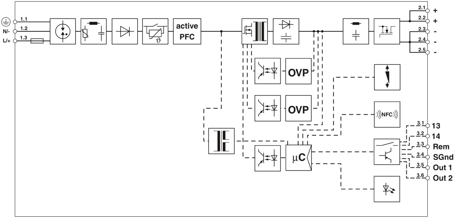
Integrated decoupling MOSFET maximizes system availability and operational safety
Double overvoltage protection (OVP) switches the output off in the event of an error to reliably protect the loads against overvoltages.
Protective coating offers protection against dust, corrosive gases, and humidity
ATEX/IECEx approval in accordance with IEC 60079-0,-7, -11, and -15
Wide temperature range allows use under extreme ambient conditions of -40°C to +75°C
PHOENIX CONTACT AG
Zürcherstrasse 22, CH-8317 Tagelswangen