
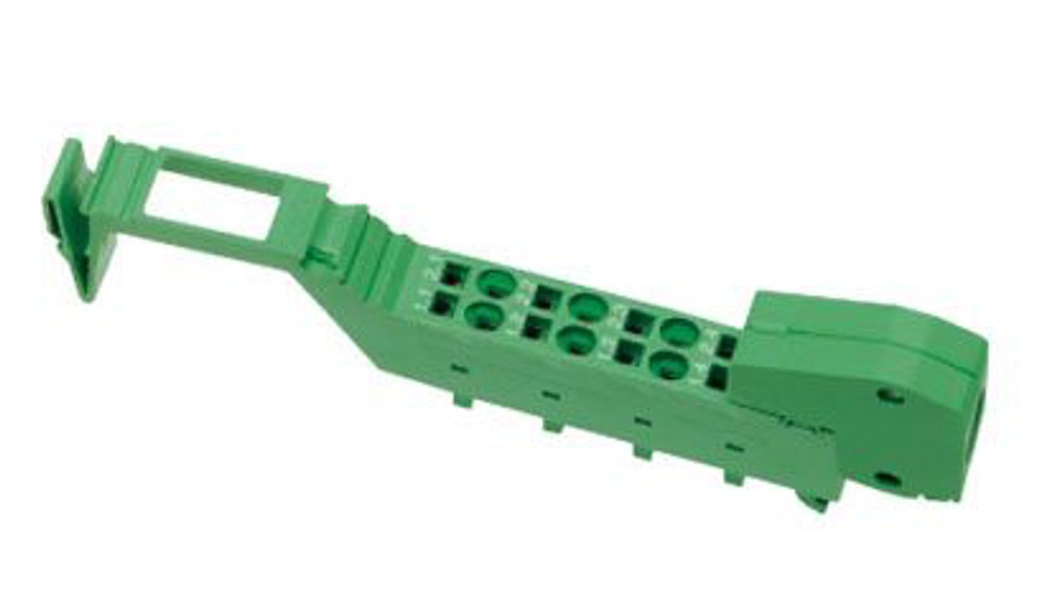
The terminal is designed for use within an Inline station. It is used to acquire analog voltage and current signals.
IB IL AI 2/SF-230-PAC
-
Analog module
2861577
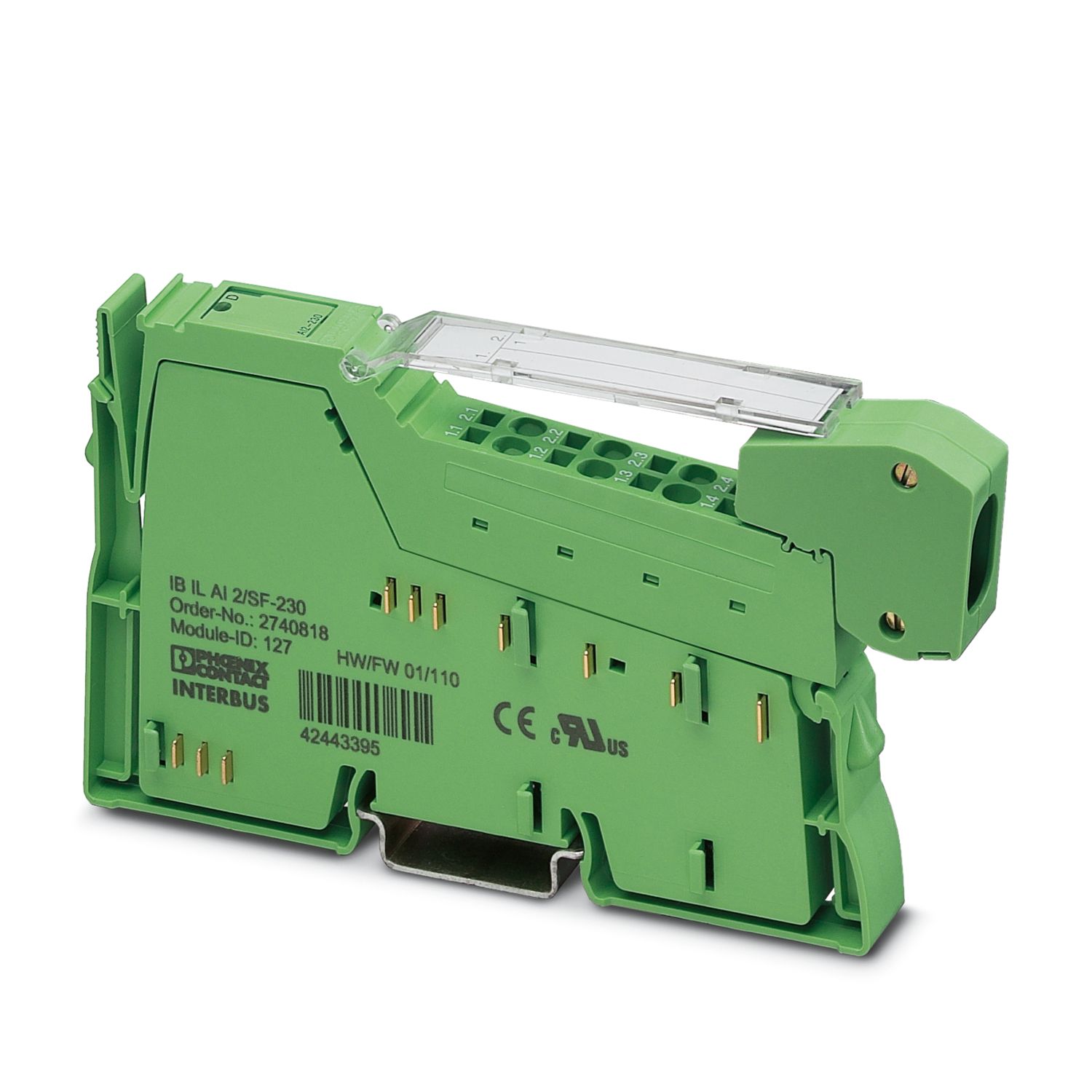

Inline, Analog input terminal, Analog inputs: 2, 0 V ... 10 V, -10 V ... 10 V, 0 mA ... 20 mA, 4 mA ... 20 mA, -20 mA ... 20 mA, connection technology: 2-conductor, transmission speed in the local bus: 500 kbps, 3 dB base frequency at 230 Hz, degree of protection: IP20, including Inline connector and labeling field
Free download available.
Downloads
Product details
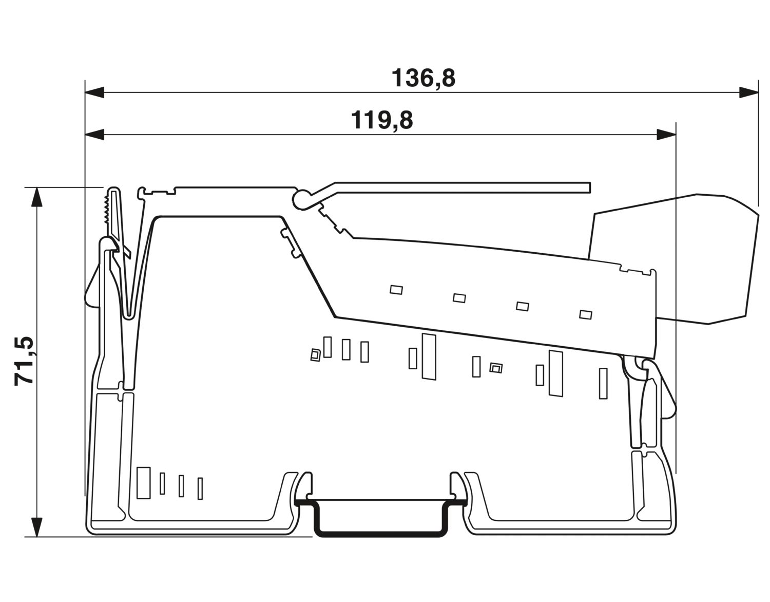
| Dimensional drawing |
|
| Width | 12.2 mm |
| Height | 136.8 mm |
| Depth | 71.5 mm |
| Note on dimensions | Housing dimensions |
| Note on application | |
| Note on application | Only for industrial use |
| Inline local bus | |
| Number of interfaces | 2 |
| Connection method | Inline data jumper |
| Transmission speed | 500 kbps |
| Module | |
| ID code (dec.) | 127 |
| ID code (hex) | 7F |
| Length code (hex) | 02 |
| Length code (dec) | 02 |
| Process data channel | 32 bit |
| Input address area | 4 Byte |
| Output address area | 4 Byte |
| Register length | 32 bit |
| Required parameter data | 6 Byte |
| Required configuration data | 4 Byte |
| Analog: General | |
| Input name | Analog inputs |
| Description of the input | Single-ended inputs, voltage or current |
| Number of inputs | 2 |
| A/D conversion time | typ. 120 µs (per channel) |
| Connection method | Inline shield connector |
| Connection technology | 2-conductor |
| Note regarding the connection technology | shielded |
| Current input signal | 0 mA ... 20 mA |
| 4 mA ... 20 mA | |
| -20 mA ... 20 mA | |
| Input resistance current input | 50 Ω (Shunt) |
| Voltage input signal | 0 V ... 10 V |
| -10 V ... 10 V | |
| Input resistance of voltage input | > 220 kΩ |
| Data formats | IB IL, IB ST, IB RT, standardized representation |
| Limit frequency (3 dB) | 230 Hz |
| Common mode voltage range signal - ground | 40 V (Between current input and functional ground) |
| 40 V (between voltage input and functional ground) | |
| Measuring principle | Successive approximation |
| Measured value resolution | 16 bits (15 bits + sign bit) |
| Measured value representation | 16 bit two's complement |
| Protective circuit | Surge protection; Suppressor diodes in the analog inputs |
| Product family | Inline |
| Type | modular |
| Installation location | Control cabinet |
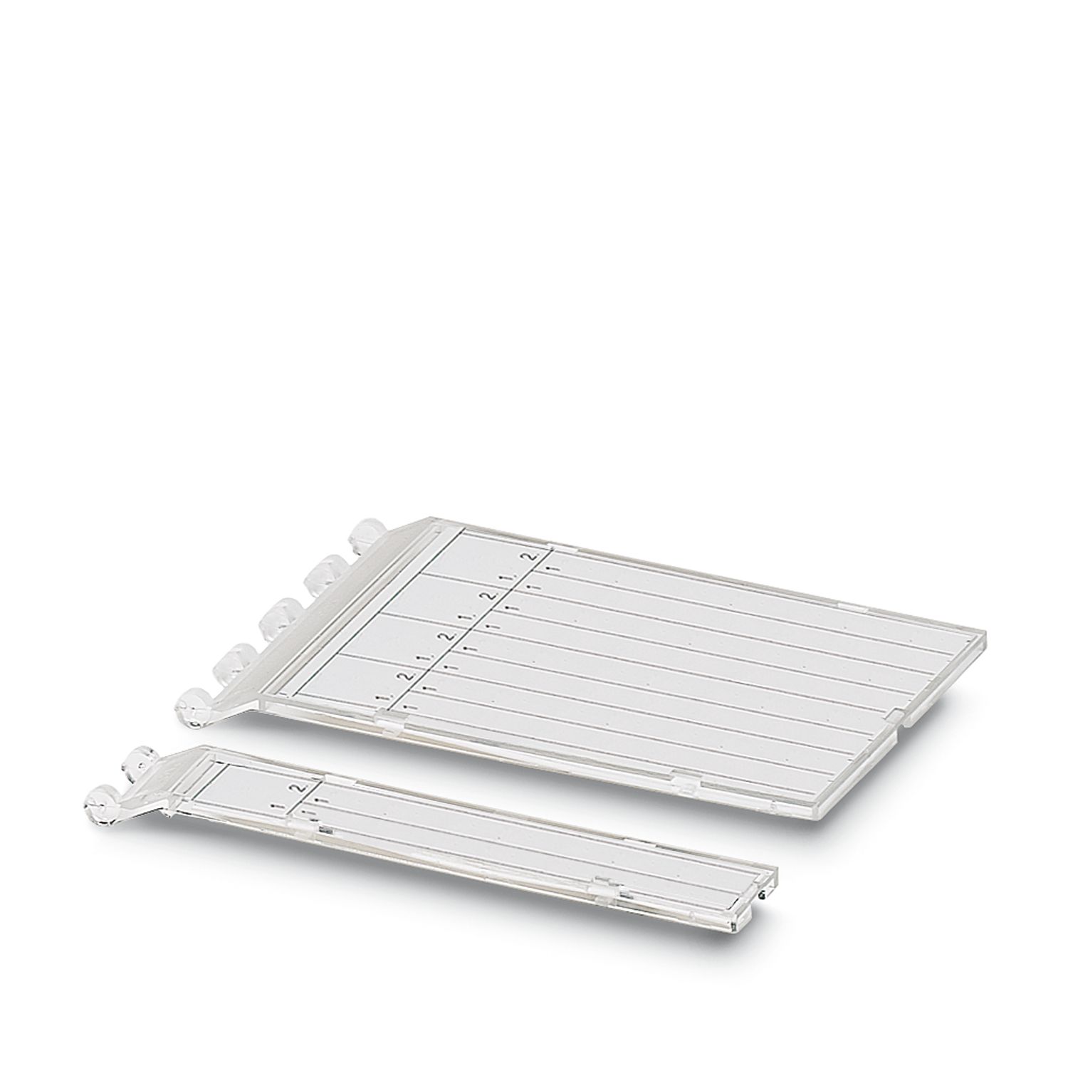
| Scope of supply | including Inline connector and labeling field |
| Operating mode | Process data operation with 2 words |
| Special properties | 3 dB base frequency at 230 Hz |
| Diagnostics messages | Failure of the internal I/O supply yes |
| I/O error Error message in the process data | |
| User error Error message in the process data | |
| Insulation characteristics | |
| Overvoltage category | II (IEC 60664-1, EN 60664-1) |
| Pollution degree | 2 (IEC 60664-1, EN 60664-1) |
| Maximum power dissipation for nominal condition | 0.9 W |
| Potentials: Communications power (UL) | |
| Supply voltage | 7.5 V DC (via voltage jumper) |
| Current draw | max. 60 mA |
| typ. 45 mA | |
| Potentials: Supply of analog modules (UANA) | |
| Supply voltage | 24 V DC (via voltage jumper) |
| Supply voltage range | 19.2 V DC ... 30 V DC (including all tolerances, including ripple) |
| Current draw | max. 18 mA |
| typ. 13 mA | |
| Electrical isolation/isolation of the voltage ranges | |
| Test voltage: 7.5 V supply (bus logic), 24 V supply UANA / I/O | 500 V AC, 50 Hz, 1 min |
| Test voltage: 7.5 V supply (bus logic), 24 V supply UANA / functional ground | 500 V AC, 50 Hz, 1 min |
| Test voltage: I/O/functional ground | 500 V AC, 50 Hz, 1 min |
| Connection technology | |
| Connection name | Inline connector |
| Conductor connection | |
| Connection method | Spring-cage connection |
| Conductor cross-section rigid | 0.08 mm² ... 1.5 mm² |
| Conductor cross-section flexible | 0.08 mm² ... 1.5 mm² |
| Conductor cross-section AWG | 28 ... 16 |
| Stripping length | 8 mm |
| Inline connector | |
| Connection method | Spring-cage connection |
| Conductor cross-section, rigid | 0.08 mm² ... 1.5 mm² |
| Conductor cross-section, flexible | 0.08 mm² ... 1.5 mm² |
| Conductor cross-section AWG | 28 ... 16 |
| Stripping length | 8 mm |
| Ambient conditions | |
| Ambient temperature (operation) | -25 °C ... 55 °C |
| Degree of protection | IP20 |
| Air pressure (operation) | 70 kPa ... 106 kPa (up to 3000 m above sea level) |
| Air pressure (storage/transport) | 70 kPa ... 106 kPa (up to 3000 m above sea level) |
| Ambient temperature (storage/transport) | -25 °C ... 85 °C |
| Permissible humidity (operation) | 10 % ... 95 % (non-condensing) |
| Permissible humidity (storage/transport) | 10 % ... 95 % (non-condensing) |
| Protection class | III (IEC 61140, EN 61140, VDE 0140-1) |
| Mounting type | DIN rail mounting |

Your advantages
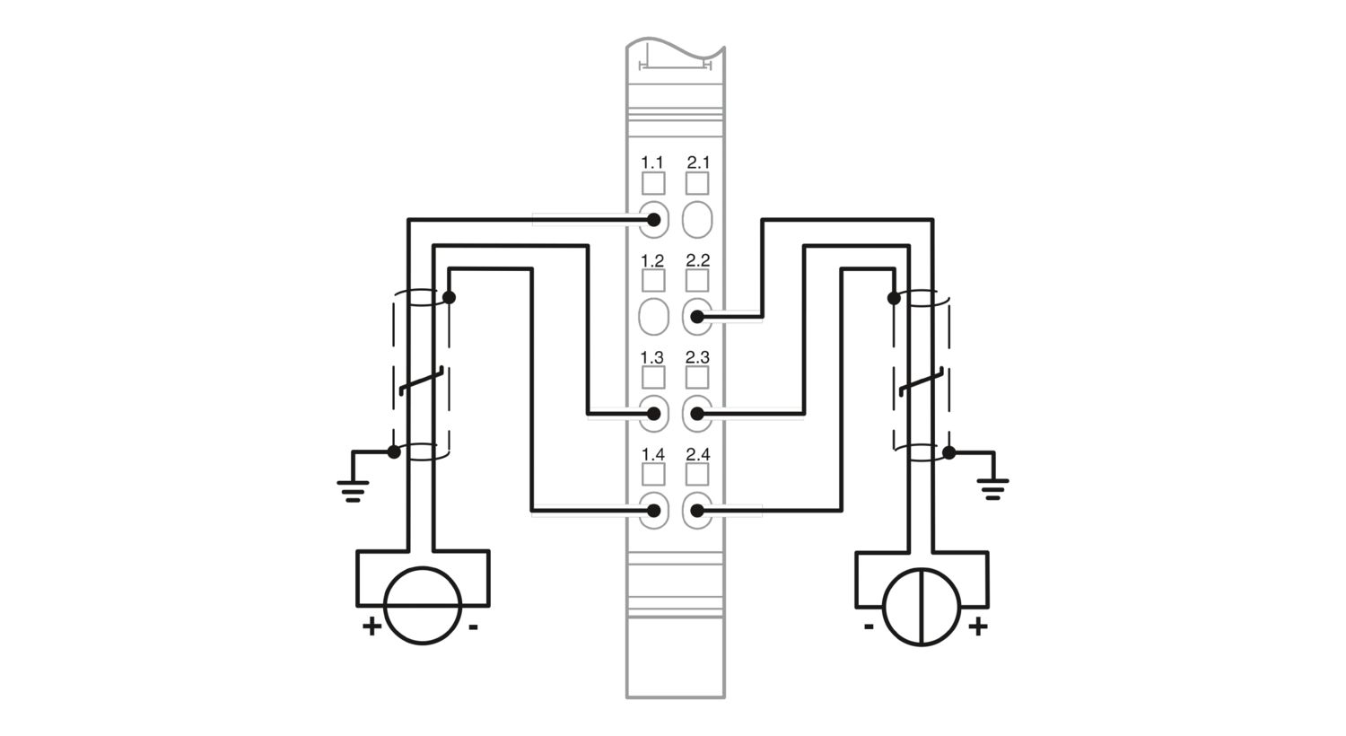
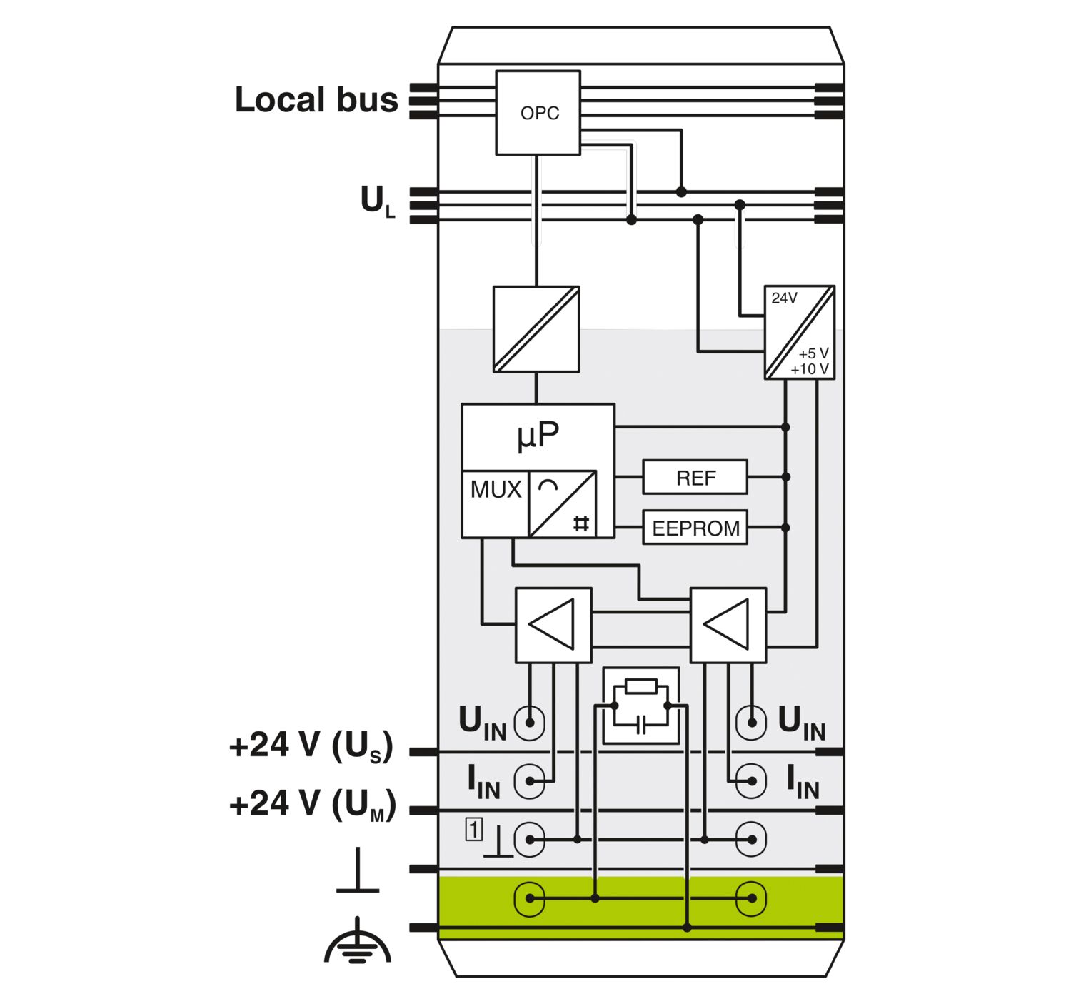
2 analog single-ended signal inputs for the connection of either voltage or current signals
Connection of sensors in 2-conductor technology
Current ranges: 0 mA ... 20 mA, 4 mA ... 20 mA, ±20 mA
Voltage ranges: 0 V ... 10 V, ±10 V
The channels are parameterized independently of one another via the bus system
Measured values can be represented in four different formats
Resolution depends on the representation format and the measuring range
Process data update of both channels within a max. of 1.5 ms