Overview
What you will find in this section:
All devices are equipped with an Ethernet interface (RJ45 socket X1) for Modbus TCP, REST API, MQTT, Webserver and BACnet IP communication. Additional Ethernet Interfaces (with RJ45 sockets X2 and X3) or an serial interface (with RS-485 socket) are available optionally for Modbus/RTU, BACnet MS/TP, PROFINET and EtherNet/IP communication.
Modbus TCP, REST API, MQTT, Webserver and BACnet IP (optional) via X1
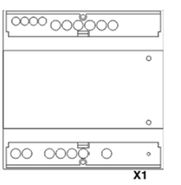
|
X1 |
Modbus/TCP, REST API, Webserver, BACnet IP (optional) |
Write and read access |
The device configuration can be performed via this Ethernet interface which supports 10/100 Mbit full/half duplex communication. It is recommended to use at least Cat.5 cables (EIA/TIA-568) for installation. Up to four clients can access the interface simultaneously.
IP addressing
The EMpro devices can be assigned both a static and a dynamic IP configuration.
Current devices support IPv4.
In the delivery state, the devices use a static IP configuration with the following parameters:
|
IP address |
192.168.1.2 |
|
Subnet mask |
255.255.255.0 |
|
Default gateway |
0.0.0.0 |
|
DNS server |
0.0.0.0 |
The entry IP 0.0.0.0, e.g., for the default gateway, indicates that no default gateway has been configured.
When the dynamic IP assignment is used, the device receives its IP configuration via the DHCP protocol from another DHCP server in the same network.
Configuration of the communication interface
You can adapt the following parameters of the network interface:
|
Function |
Information |
Web server |
Display |
Register |
|
Mode |
The mode is used to define whether a static IP configuration from the device memory has to be used, or a dynamic configuration should be performed via DHCP instead. |
x |
x |
x |
|
IP address |
This setting is only used in static mode. Here, the static IP address of the device is configured. In dynamic mode, this parameter is supplied by the DHCP server. |
x |
x |
x |
|
Subnet mask |
This setting is only used in static mode. Here, the static subnet mask of the device is configured. In dynamic mode, this parameter is supplied by the DHCP server. |
x |
x |
x |
|
Default gateway |
This setting is only used in static mode. Here, the static IP address of the default gateway to be used is configured. In dynamic mode, this parameter is supplied by the DHCP server. The default gateway is required to allow communication across network boundaries. This is defined by means of the subnet mask. |
x |
x |
x |
|
DNS server |
This setting is only used in static mode.Here, the static IP address of the DNS server to be used is configured. In dynamic mode, this parameter is supplied by the DHCP server. The DNS server is used to perform name resolutions, e.g., for an NTP time server. |
x |
x |
x |
|
Device name |
The device supports the NetBios name service. With this protocol, the device can be addressed using a host name, without knowing the IP address of the device. The device has three NetBios names. Two of these names are manufacturer-specific and cannot be modified. You can change the third name. The following names have been defined: First manufacturer-specific NetBios name: <DEVICE_NAME> (e.g., EEM-MA770) Second manufacturer-specific NetBios name: eem<SERIAL_NUMBER> (e.g.,eem1234567890) User-specific NetBios name: <YOUR_DEVICE_NAME> (default: <DEVICE_NAME>) |
x |
x (read only) |
x |
Status of the communication interface
If the network interface is ready, this is indicated by the  icon on the display.
The following conditions must be met for the network interface to be ready:
- Device start completed
- Network link established
- IP configuration valid
- Always true for static configurations
- True for dynamic configurations after the IP configuration has been received by the DHCP server
The current status of the network interface can be viewed via the WBM, the display, Modbus and BACnet.
There are two LEDs on the RJ45 socket:
- Green LED for link status, to the left of the RJ45 connector
- Orange LED for sending activity, to the right of the RJ45 connector
Topology
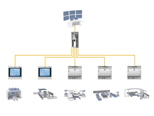
Multiple EMpro devices can be connected to higher-level control systems in a star topology.
Modbus RTU and BACnet MS/TP (optional) via RS-485
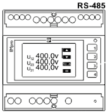
|
RS-485 |
Modbus/TCP, BACnet MS/TP (optional) |
Write and read access |
The device configuration can be performed via this RS-485 interface.
Addressing & Settings
In the delivery state, the devices use a configuration with the following parameters:
|
Address |
1 |
| Transmission speed | 9,6 kBit/s |
| Parity (only Modbus) | Even |
Please observe the following:
- Each server is assigned an address between 1 and 247 (Modbus RTU) or 0 and 127 (BACnet MS/TP).
- Each address is used only once.
- There is only one client per RS-485 network.
- All devices use the same parameters for the baud rate, stop bits and parity.
You can configure the following parameters that are supported by the RS-485 interface:
- Baud rates: 2400 (Modbus RTU), 4800 (Modbus RTU), 9600, 19200, 38400, 57600 and 115200 bps
- Autobauding (BACnet MS/TP): If activated, the device listens to the network and automatically detects the baud rate. The configured baud rate is then ignored.
- Parity (Modbus RTU): even, odd, none
- Max Master (BACnet MS/TP): Maximum master address for token passing process in the network
- Max Info (BACnet MS/TP): Maximum of exchanged info frames until the token is passed to next device in the network
Connections and designations
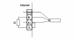
The RS-485 interface has four assigned terminals.
|
GND |
Shield of signal line |
|
B- and A+: |
Signal lines |
|
Ω: |
120 Ω resistor |
The non-inverted signal can have the following designations: A, +, A+, TxD+/RxD+, D+
The inverted signal can have the following designations: B, -, B-, TxD-/RxD-, D-
To ensure that the communication is guaranteed even in the event of malfunctions, ensure that the following conditions are met in the RS-485 network:
- Twisted pair conductors (A and B) (stranding)
- Shielded conductors (GND)
- Termination resistors (and a bias network)
NOTE: If you want to activate the integrated 120 Ω resistor, bridge the terminals Ω and A+.
Topology
Multiple EMpro devices can be connected to higher-level control systems in a serial line topology.
The smallest network via RS-485 that makes sense consists of two devices:
- 1 x client 1 x server
The typical limit is 32 devices:
- 1 x client 31 x servers

PROFINET or EtherNet/IP™ via X2 and X3
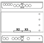
|
X2 |
PROFINET or EtherNet/IP™ |
Read access |
| X3 | PROFINET or EtherNet/IP™ | Read access |
The interfaces (X2 and X3) do not offer any options for device configuration and can therefore not be reached via the display or the web server.
The interfaces only offer a read function for the data via the dual ports (2xRJ45).
You can use one or two communication protocols with only one cable. To do so, bridge interfaces X1 and X3. Via the interface X2, both protocols (Modbus/TCP and PROFINET, or Modbus/TCP and EtherNet/IP™) can now be used in parallel.
Addressing
The associated IP addresses are assigned accordingly via the controller.
Topology
Multiple EMpro devices can be connected to higher-level control systems in a star topology and also via Daisy Chain or Ring Topology over Ethernet.

Related topics
See also