Voltage Quality
What you will find in this section:
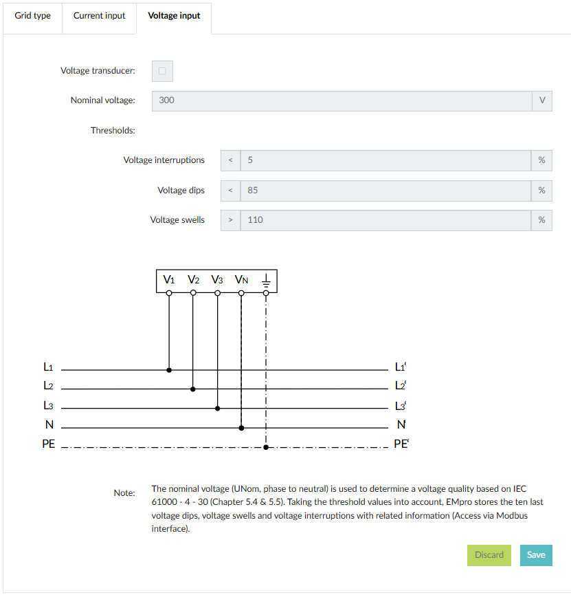
Voltage quality
The device is able to capture voltage interruptions, voltage dips and voltage swells based on IEC 61000-4-30 (Chapter 5.4 & 5.5). The measurements are defined in EN 61557-12. The reference voltage is the nominal voltage (phase to neutral) which needs to be set in the basic voltage input configuration. For each type of voltage threshold violation the device stores the last 10 events with complete parameter information including time stamp. These information can be read out via modbus interface. The event is stored at the time when the event is completed (T2 or T4).
Parameter information of events:
- Cause of voltage threshold violation
- Lowest voltage value during event (voltage dip) / Highest voltage value during event (voltage swell)
- Duration of voltage threshold violation
- Start time of voltage threshold violation (date & time in UTC format)
For voltage interruption only the start time of voltage threshold violation (date & time) is stored.
Voltage interruptions
The threshold value range is adjustable from 5%...10% of nominal voltage (Un).
The voltage interruption Uint has the behavior as the voltage dip Udip.
The difference is that the threshold values are very small and the values of the lowest
voltages are no longer output.
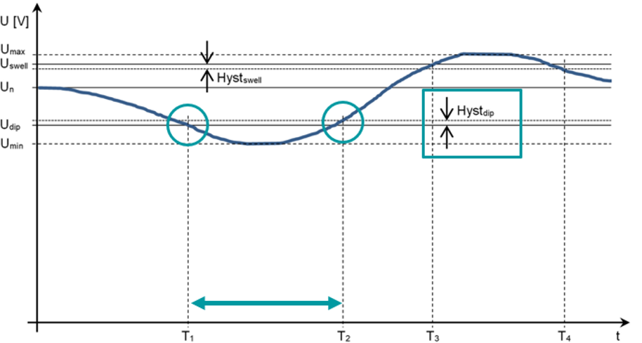
Voltage dips
The threshold value range is adjustable from 20%...100% of nominal voltage (Un).
T1: The signal drops down below the threshold value Udip
T2:The signal exceeds the threshold value Udip + Hysteresisdip
T2-T1: Duration of voltage dip Udip
Voltage swells
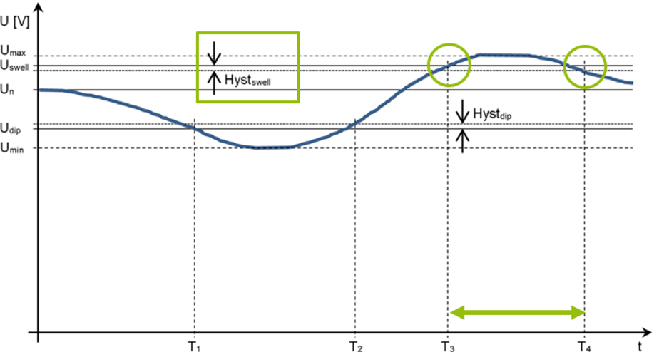
The threshold value range is adjustable from 100%...120% of nominal voltage (Un).
T3: The signal exceeds the upper threshold value Uswl
T4:The signal drops down below the threshold value Uswl - Hysteresisswl
T4-T3: Duration of voltage swell Uswl
Important note: Ensure that the device supply is guaranteed at all times, especially when recording voltage interruptions.
Configuration
Configuration of thresholds is possible via WBM. The default value for the hysteresis is 2 % and can be changed via modbus interface only.