Harmonics
What you will find in this section:
Signal analysis
Simplified (according to Joseph Fourier), a periodic function f(t) with period T>0 can be represented by a series of sine and cosine functions whose frequencies are integer multiples (k=0-∞) of the fundamental frequency ω=2π/Τ,
, a periodic function f(t)_2.png)
or divided into real part and imaginary part
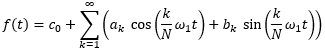
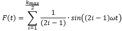
The following figure shows an example of rectangular synthesis according to Fourier.
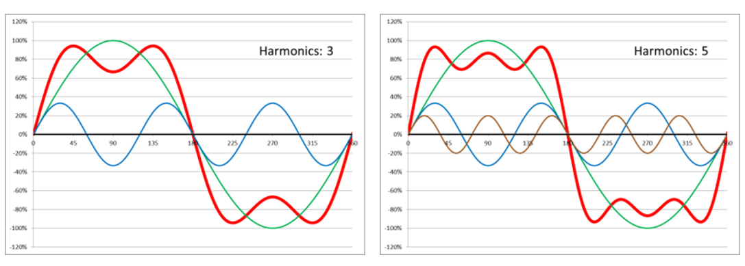
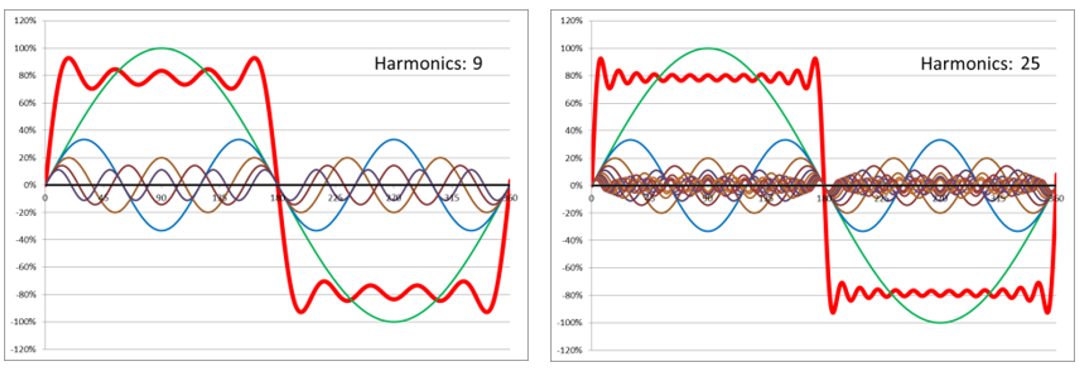
Here, a square wave signal is added up from sine waves. The following applies for all odd harmonics k=1 to kmax: F(t)k=1/k-sin(kωt). These signals are added together to produce the square wave. kmax is indicated in the diagrams.
Harmonics
Calculation of the amplitudes of the harmonics
According to DIN EN 61000-4-7:2009-12 Chapter 3.1 Terms relating to frequency analysis, the following calculation rules apply:
The continuous signal f(t) is sampled with a number M of supporting points per period. Several (N) periods can be sampled for the calculation. The standard requires 10 at 50Hz or 12 at 60Hz base frequency (i.e. approx. 200ms). As an FFT is to be used, the number of supporting points must always be a power of 2.
For further consideration, the formulas from the standard DIN EN 61000-4-7:2009-12 Chapter 3.1 have already been adapted to the discrete signal due to sampling. It is also assumed that only one period is considered. However, the discrete sampled values can be mean values over N periods. The continuous signal f(t) becomes the discrete-time signal F[A0, A1, ... AM]. Am denotes the amplitude at time m.
For each harmonic (k = 0 to Max), the real and imaginary components are calculated for all samples (m = 0 to M). Max is the highest harmonic under consideration. The DIN EN 61557-12 standard, Table 41, specifies the requirement to measure up to the 50th order. In DIN EN 61000-4-7, hmax is specified as 40. (EN 61000-4-7)
For this purpose, the sampled value F[Am] at the point ω=2π-m/M of the supporting point m is multiplied by the sine and cosine at the point ω=2π-m/M-k (point ω=2π-m/M multiplied by the number of harmonics k), added up and divided by half the number of supporting points.
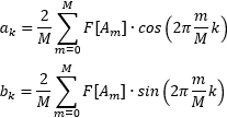
This results in the real component ak and the imaginary component bk of the harmonic k.
The first harmonic forms the fundamental frequency.
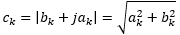
Because the real component ak and the imaginary component bk are at right angles to each other, the amplitude ck of the component with k times the frequency (fH,k) of the fundamental frequency fH,1 is calculated as:
DC component:
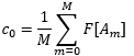
Because there is no imaginary part for the zero harmonic for the DC component (sin(0) = 0). The multiplication with the cosine is also saved since cos(0) = 1.
The RMS value YC,k of the amplitude ck is formed by

The harmonic component YH,h is identical to the spectral component YC,k, where k = h × N (YH,h = YC,h × N). Depending on requirements, the symbol Y is replaced by the symbol I for currents or by the symbol U for voltages. The index H identifies the variable I or U as a harmonic.
THD
THD in relation to the fundamental component
According to the standard DIN EN 61000-4-7, the total harmonic distortion THD is defined: THDY (symbol)
Ratio of the RMS value of the sum of all harmonic components (YH,h) up to a certain harmonic order (hmax) to the RMS value of the fundamental component (YH,1) is:
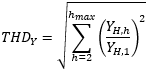
The simplified representation from the standard DIN EN 61557-12, Table A.2 is the ratio of the square root of the sum of the squares of the harmonic components up to the 63rd harmonic to the fundamental component. So hmax is specified here. The result is the same.
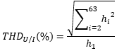
In the DIN EN 61557-12 standard, hi is defined as the harmonic component of rank i. It is not clearly defined whether the RMS value or the amplitude is meant. Since the two specifications have a linear relationship (factor √2), this is not relevant in the specified ratio. The different notations in the two cited standards result in hi ≈ YH,h.
THD in relation to the RMS value
The simplified representation from the standard DIN EN 61557-12, Table A.2 is the ratio of the square root of the sum of the squares of the harmonic components up to the 63rd harmonic to the RMS value of the alternating signal. It must be specified here that the harmonic components are RMS values.
hi = YH,h.
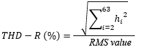
Standard DIN EN 61557-12 with RMS value = Urms for THD-Ru bzw. Irms for THD-Ri
The total RMS value is calculated from:
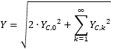
For the application with 63 harmonics, this results in the calculation rule:
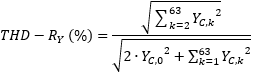
According to the definition of the distortion factor, the DC component is not taken into account when calculating the RMS value. The values cannot be compared with signals with a DC component.
Related topics