Modbus/RTU
What you will find in this section:
Modbus/RTU
In the case of Modbus/RTU, the Modbus application layer protocol is supplemented with additional information and physically sent via an RS-485 interface. The start and end of a Modbus message is coordinated by means of timings.
Modbus/RTU describes a client/server protocol. Here, the EMpro acts as Modbus/RTU server. An exception here is the gateway mode.
The additional information consists of a byte for addressing the device. Valid device addresses are in the range from 1-247.
The default setting for the devices is address 1. Address 0 is reserved for broadcast messages in the network and cannot be assigned as an address to a device.
According to the specification, addresses 248-255 are reserved and cannot be assigned to the device either.
A cyclic redundancy check (CRC) is attached to the Modbus message as additional information. The CRC is used to detect transmission errors. The calculation and the polynomial used are documented in the Modbus specification.
The Modbus/RTU protocol is supported by all EMpro versions with an RS-485 interface.
Topology
The smallest network via RS-485 (Modbus) that makes sense consists of two devices:
- 1 x client 1 x server
The typical limit is 32 devices. - 1 x client 31 x servers
The largest network via RS-485 (Modbus) that makes sense consists of 248 devices, because of the addressing:
- 1 x client 247 x servers

Using connections and designations

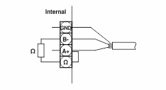
The RS-485 interface has four assigned terminals.
|
GND |
Shield of signal line |
|
B- and A+: |
Signal lines |
|
Ω: |
120 Ω resistor |
The non-inverted signal can have the following designations: A, +, A+, TxD+/RxD+, D+
The inverted signal can have the following designations: B, -, B-, TxD-/RxD-, D-
To ensure that the communication is guaranteed even in the event of malfunctions, ensure that the following conditions are met in the RS-485 network:
- Twisted pair conductors (A and B) (stranding)
- Shielded conductors (GND)
- Termination resistors (and a bias network)
NOTE: If you want to activate the integrated 120 Ω resistor, bridge the terminals Ω and A+.
Parameters for using Modbus via RS-485

|
Status |
The “Status” area gives an overview of the current Modbus configuration. |

Please observe the following:
- Each server is assigned an address between 1 and 247.
- Each address is used only once.
- There is only one client per RS-485 network.
- All devices use the same parameters for the baud rate, stop bits and parity.
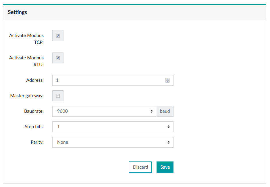
You can configure the following parameters that are supported by the RS-485 interface:
- Baud rates: 2400, 4800, 9600, 19200, 38400, 57600 and 115200 bps
- Stop bits: 1, 2
- Parity: even, odd, none
The parameters can also be set via Modbus/TCP.
Related topics