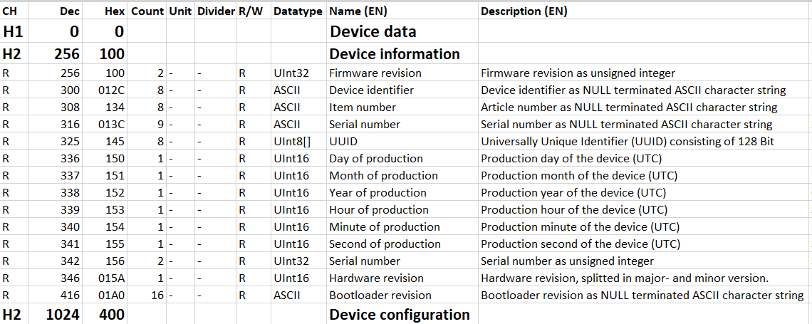
Description of the Register Table
What you will find in this section:
Description of the register table

Content of the line (CH)
The first line of the register table contains information about the content of the respective line or column.
H1 … Hn: Heading
An “H” with a number indicates a heading. The number behind it indicates the hierarchical level.
To keep the register entries structured and readable, they are divided by headings.
R: Register
The “R” stands for Register and designates the lines that each describe a register.
Only lines that also contain registers are relevant for automatic processing of the register table.
U: Unused
The “U” describes unused entries. These can be, e.g., address ranges that do not have a function (yet) and are reserved.
E: End
The “E” describes the end of the table.
Dec: Decimal address
The second column of the register table contains register addresses in decimal form.
Hex: Hexadecimal address
The third column of the register table contains register addresses in hexadecimal form.
Count
The “Count” column displays the number of registers required for the function described in this line. The required number is directly dependent on the data type.
Short designation
The “Short designation” column contains the abbreviated designations of the registers. The short designations are unique, so that all other data can be referenced using the short designations.
Unit
The unit for the process values is given in the “Unit” column. For example, the unit for the voltages is volt [V].
Divider
The “Divider” column states the divider by which the value is to be divided to get the correct value. This is necessary, e.g., if the data type is an integer value, but a decimal fraction has to be entered.
Example:
If the harmonics are specified as percentage with signed integer, but have to be output with a precision of a tenth of a percent. In this case, for example, 15.2% is used as 152 with divider 10.
R/W: Read/write access
This column specifies which access is permitted for the respective register.
R: Read only
These registers can only be read. Attempting write access to these registers causes an error.
R/W: Read and write
It is possible to both read and write to these registers.
W: Write only
These registers can only be written. Attempting read access to these registers causes an error.
W/R0: Write only and read 0
These registers can only be written. Read access to these registers results in a zero as response.
Datatype
This column contains the data type to be used for decoding the contents of each respective register.
ASCII
Each register (16 Bit) contains two ASCII characters. When the number is entered, the number of individual registers contained in the character string is determined.
Example:
Dez:1234567
Hex: 0X31, 0X32, 0X33, 0X34, 0X35, 0X36, 0X37
Zero-terminated: “12345670”
Hex: 0X31, 0X32, 0X33, 0X34, 0X35, 0X36, 0X37, 0X00
Number of registers = 4: Hex: 0X3231, 0X3433, 0X3534, 0X0037
Bit mask
Each bit (bit 15-bit 0) of the register (16 bit) is evaluated individually.
Example: “Resetting the tariff meter”
Bit 0: Reset tariff 1
Bit 1: Reset tariff 2
Bit 2: Reset tariff 3
Bit 3: Reset tariff 4
An individual tariff meter, or any combination of meters from all tariff meters can be reset.
Bool
This data type makes a logical statement.
0: false
1: true
Fl32
IEEE-754-single number 1.8.23 (32 bits, two 16-bit registers):
1 sign bit: positive and negative
8 exponent bits: ≈ value range of 38 decimal places
23 mantissa bits: ≈ precision of 6 decimal places
Decimal value range: ±1.175·10-38 to 3.40282·1038
Register in float
32-bit value from the registers: 0X41340000 = 01000001 00110100 00000000 00000000b
Bit31 = 0: SB, sign bit. This number is positive.
Bit30 - Bit23: E, exponent. In this case: 130.
Bit22 - Bit0: M, mantissa. Here it is 3,407,872.
Z = 11.25
Float in register
Floating-point number X = 11.25
SB, sign bit. This number is positive => Bit31 = 0 / 0X00 / 0b
In this case 130 => Bit30 - Bit23 = 130 / 0X82 / 10000010b
mantissa. Here it is 3,407,872 => Bit22 - Bit0 = 3407872 / 0x340000 / 0110100 00000000 00000000b
32-bit value for the register: 0X41340000 = 01000001 00110100 00000000 00000000b
SInt16
Signed integer:
2 byte, 16 bit
Value range: -215 … 215-1
-32,768 … 32,767
UInt16
Unsigned integer:
2 byte, 16 bit
Value range: 0 … 216-1
0 … 65,535
UInt32
Unsigned integer:
4 byte, 32 bit
Value range: 0 … 232-1
0 … 4294967295
SInt32
Signed integer:
4 byte, 32 bit
Value range: -231 … 231-1
-2,147,483,648 … 2,147,483,647
UInt8
Only the low byte of the register is evaluated.
1 byte, 8 bit
Value range: 0 … 28-1 = 0 … 255
UInt[]
Array of UInt8 values. Their order follows that of the ASCII registers.
These data types are used, e.g., for the MAC addresses.
Three registers are required for the six bytes.
E.g., 00:A00:45:66:4F:41
Name
Here, the name of the respective register is entered. It may be longer than the short designation, so that it is readable and expresses the function of the register.
Description
In this column, the function of the register is described in detail.